FREE 1 to 3-Day Delivery on Orders $149+ Details
How to Install S & B Cold Air Intake w/ Oiled Cleanable Cotton Filter (15-17 5.0L) on your Ford F-150
Installation Time
30 minutes
Tools Required
- 10mm, 13mm Wrench & Socket
- 5/16” Nut Driver & 1/4” Nut Driver or Flat Blade Screwdriver
- Phillips Screwdriver, Pliers or Channel Locks

Shop Parts in this Guide
BEFORE YOU START
• Please read the entire product guide before proceeding.
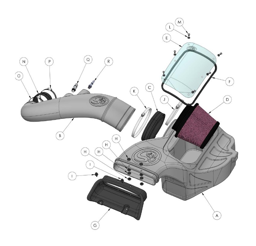
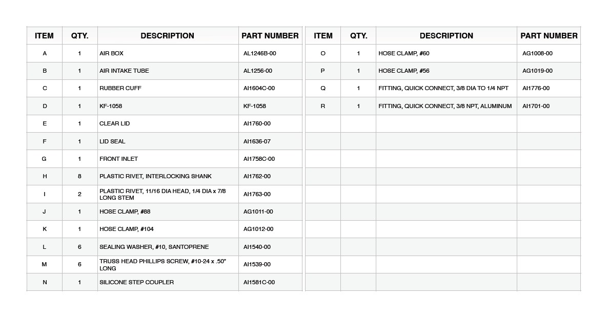
• Ensure all components listed on page 4 are present.
• If you are missing any of the components, call our customer support at (909) 947-0015.
• Do not work on your vehicle while engine is hot.
• Make sure the engine is turned off and the vehicle is in Park and the Parking Brake is set.
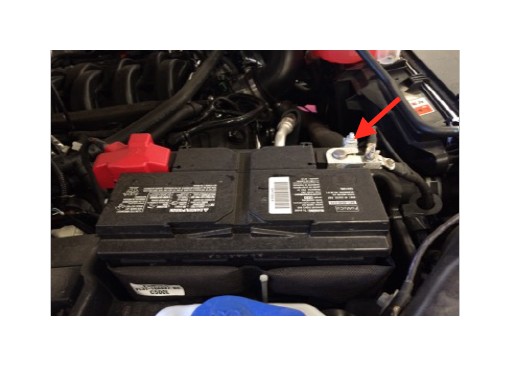
1. With the ignition switched off and the parking brake set, disconnect the negative battery cable on the battery. Note: Failure to disconnect the battery may cause the CEL to illuminate upon completion of the installation and subsequent operation. Do not skip this step!
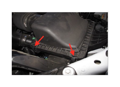
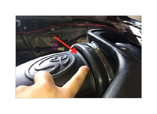
2. Loosen the hose clamp by the stock air box and pull the tube out.
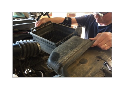
3. Unlatch the two latches on the stock air box.
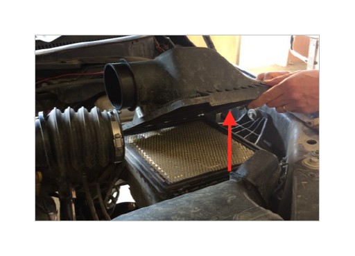
4. Lift and remove both the lid and air filter.
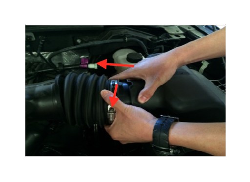
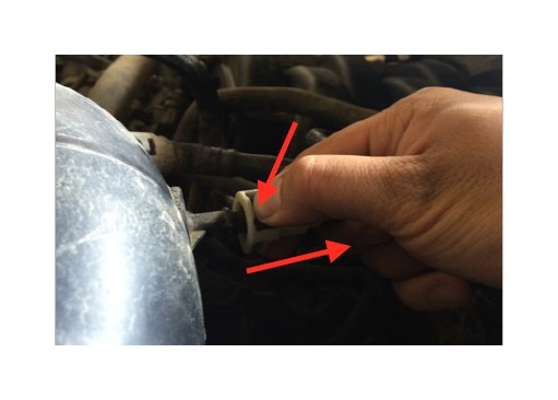
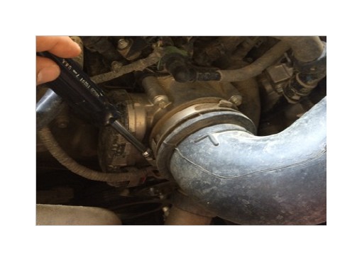
5. Disconnect the vacuum line. Push down on the black clip and pull the hose connector out of the hose barb.
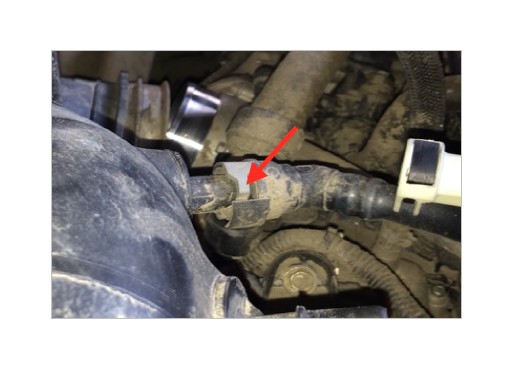
6. Pull on the lever to remove the PCV hose from the hose barb.
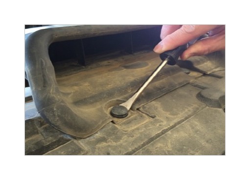
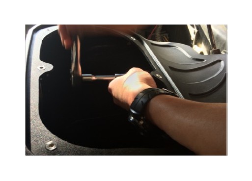
7. Remove the retaining bolt on the stock air box using a 13mm socket. Note: The retaining bolt will be reused again in Step 18.
8. Remove the plastic rivets on the stock air scoop using a flat head screwdriver.
9. Lift and remove the stock air box.
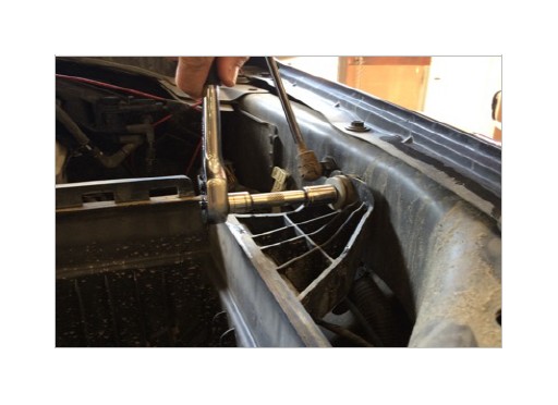
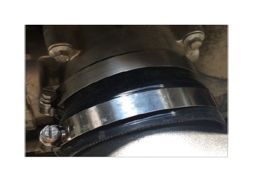
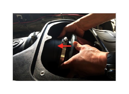
10. Loosen the hose clamp at the throttle body.
11. Remove the stock air tube.
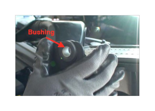
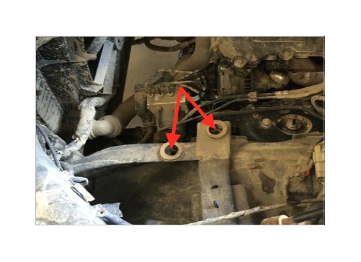
12. Remove the grommet and metal bushing from the stock air box. Removing the metal bushing first will help make removing the grommet easier.
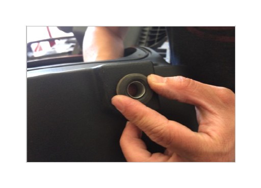
13. Install the grommet into Air Box (A) first and then install the metal bushing from the inside.
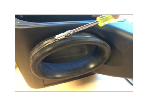
14. Install the Rubber Cuff (C) and Hose Clamp #104 (K) onto the side of the Air Box (A). Make sure that the rubber pull tab on the tube seal is on the bottom. Tighten the hose clamp.
15. Install the Front Inlet (G). Use the supplied Plastic Rivet (H) to secure the front inlet to the Air Box (A). Use two plastic rivets on each hole and pinch them together to lock them in place.
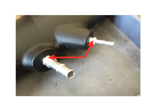
16. Install the two Quick Connect Fitting (Q & R) until snug. Do not over tighten. You may also want to use some teflon tape to create a better seal. Warning: Over tightening may strip the inserts.
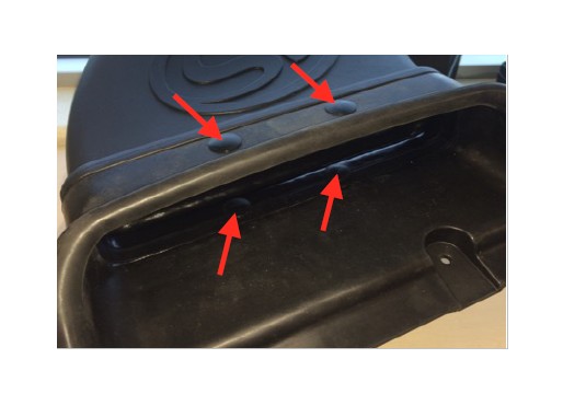
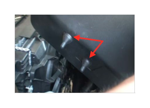
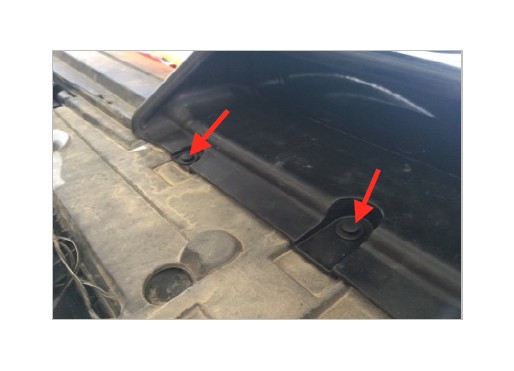
17. Install the Air Box (A). Make sure that the box prongs are aligned with the factory grommets. Push down on the air box to make sure that the prongs are completely seated.
18. Reinstall the retaining bolt removed in Step 7 and tighten the bolt to secure the Air Box (A). Install the retaining bolt from inside the air box.
19. Install the Silicone Step Coupler (N) and two Hose Clamp #60 & #56 (O & P) onto the throttle body.
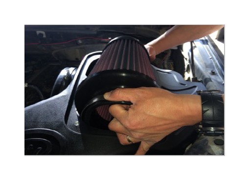
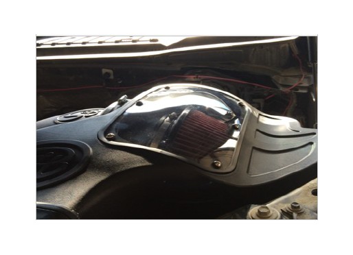
20. Place the Air Filter (D) and Hose Clamp #88 (J) inside the Air Box (A). Turn the filter sideways and slide it into the air box.
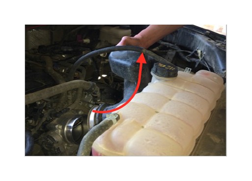
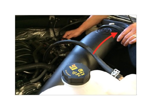
21. Feed the Air Intake Tube (B) underneath the coolant line through the Rubber Cuff (C) until the bead on the air intake tube meets up to the rubber cuff. Slide the Air Filter (D) over the tube until the tube bottoms out on the filter flange step.
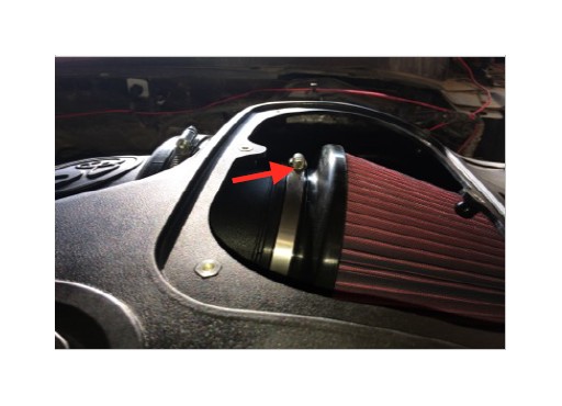
22. Tighten the Hose Clamp #88 (J) at the Air Filter (D).
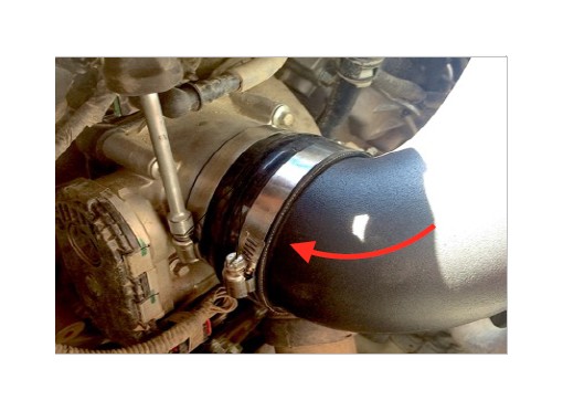
23. Insert the Air Intake Tube (B) into the Silicone Step Coupler (N) at the throttle body. Once everything is in place, tighten Hose Clamp #56 & #52 (O & P).
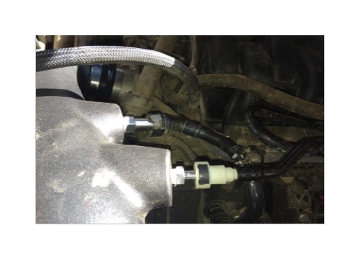
24. Reconnect the vacuum line. Push in the connector over the Quick Connect Fitting (R) until you hear it snap into place.
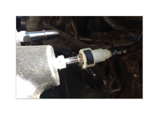
25. Reconnect the PCV hose. Push in the connector over the Quick Connect Fitting (Q) until you hear it snap into place.
26. Secure the Front Inlet (G). Firmly push down on the center pin of the Plastic Rivet (I) until it locks into the closed position.
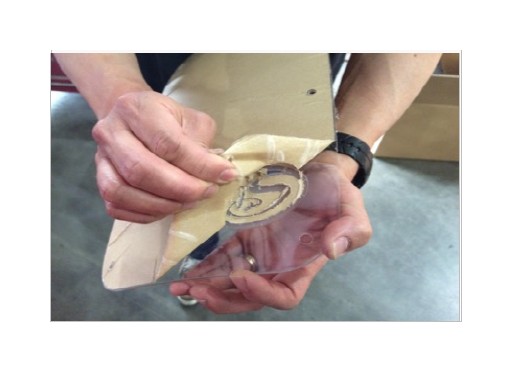
27. Remove the protective covering from the Clear Lid (E).
28. Install the Lid Seal (F) around the Clear Lid (E).
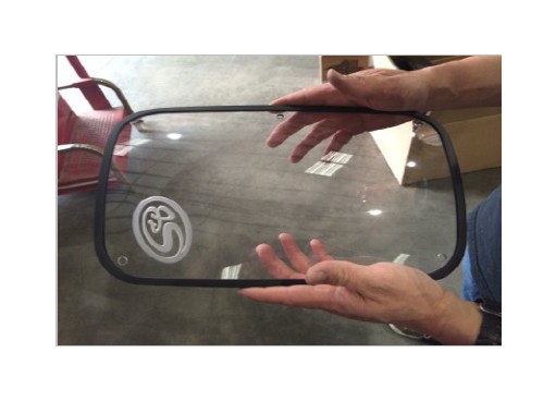
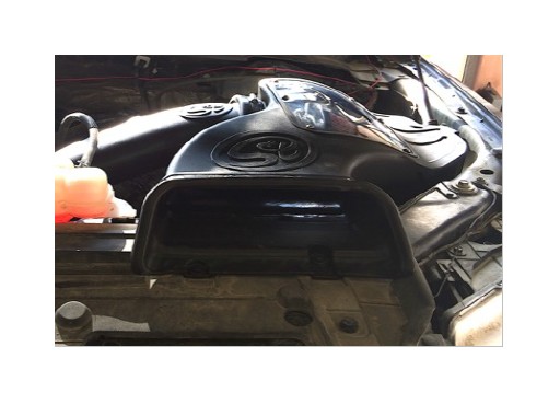
29. Install the Clear Lid (E) on top of the Air Box (A) and secure the lid using the six provided Truss Head Phillips Screw (M) and Sealing Washer (L). Do not over tighten.
30. Reconnect the negative terminal on the battery. Inspect your installation, make sure the kit is properly positioned and all fasteners are secure. Affix the ID/CARB label near the kit under the hood. The installation is now complete.
Performance Testing
• Engage parking brake and start your engine. Listen for abnormal noises. If an air leak is detected, re-inspect hoses and connections as they may need to be repositioned and tightened.
• S&B FILTERS recommends that you keep your OE intake system in the event it is required in the future.
• In order to maintain your warranty, all connections and components must be checked periodically for alignment and for proper tension on all connections. Failure to do so may void your warranty.
• Use only S&B FILTERS cleaning and oil products to service your filter. Using any other brand oil and or cleaners on your S&B air filter may void your warranty.
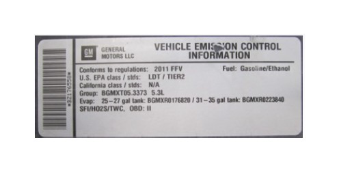
Warning!
If your vehicle has a Vehicle Emission Control Information decal affixed to the factory airbox, a new replacement label must be obtained and installed in a readily visible position in the engine compartment in order to remain CARB compliant. Failure to do so will prevent the vehicle from passing a smog check. Replacement labels can be ordered from your local dealership. Regulations state that the VECI label shall not be affixed to any equipment which is easily detached from the vehicle. Label placement, under the hood on a painted surface is recommended.
Emissions Standard
The California Air Resource Board (CARB) requires that an E.O. identification label be applied to the vehicle in order to pass a smog check inspection when a Performance Intake Kit has been installed. You must place the E.O. label provided on or near the intake kit after installation so that a smog check technician can easily verify the E.O. number. As of April 2009, S&B has never had a product where CARB denied an exemption request; however, the exemption process with CARB can take as long as 18 months. Check the status of the exemption process by looking up a specific part number at www.sbfilters.com. The CARB Exemption number and/or status is listed under the Product Details section for each part number. If the status shows as “Pending,” CARB has yet to issue an exemption. Products that have not been issued an EO number are street legal in most states, but may not be used on emission controlled vehicles in the state of California and are for off road use only. If you purchased your kit from S&B Filters directly, we will automatically mail you your Exemption Sticker when it is issued to us. If you purchased your kit from an authorized S&B Filters Dealer, log onto our web site and register to receive your Exemption Sticker