FREE 1 to 3-Day Delivery on Orders $149+ Details
How to Install Roush R2300 650HP Supercharger Kit - Phase 2 on your F-150
Installation Time
1 days
Tools Required
- Cordless Impact Wrench
- 1/4” and 3/8” Drive Ratchets with Extensions
- Metric and Standard Socket Sets (short and deep recommended)
- 1/2” Drive Ratchet or Breaker Bar
- Metric and Standard Wrench Sets
- 3/8” Drive Torque Wrench (7-35 ft-lb range)
- Short Phillips-head Screwdriver
- 5/8” Fuel Line Removal Tool
- T-20 Torx Bit Screwdriver or Socket
- 5/16” Drill Bits and Drill Motor
- Grinder/Cutoff Wheel (Angle Grinder/Dremel)
- Coolant (meeting Factory Ford specifi cation for 2011+ F-150)
- 6” Scale, Tape Measure, or Other Measuring Device
- Assembly Lubricant (White Lithium Grease or Petroleum Jelly)
- Electrical Tape
- Sharp Knife or Razor Blade
- Solder & Soldering Iron
- Heat Gun or Small Torch for Heat Shrink Tubing
- Tie Straps (Zip Ties)
- Trim Tool
- Trim Pad Tool (for pushpin removal)
- Hammer (Mini-Sledge)
- Fender Cover (2)
- Medium Strength Thread Locker - Loctite 242 (Blue) or equivalent
- Rust Preventative
- Isopropyl Alcohol
SECTION A – DISASSEMBLY
The following section will guide you through the disassembly of the stock components. Special care should be taken to label fasteners and parts that are taken off during this procedure since many will be reused:
1. Cover both fenders with fender covers to protect the vehicle fi nish.
2. Release the fuel system pressure.
NOTE: The following procedure is taken directly from the Ford Service Manual.
Fuel in the fuel system remains under high pressure even when the engine is not running. Before working on or disconnecting any of the fuel lines or fuel system components, the fuel system pressure must be relieved. Failure to do so can result in personal injury.
Do not smoke or carry lighted tobacco or open fl ame of any type when working on or near any fuel-related components. Highly fl ammable mixtures are always present and can be ignited, resulting in personal injury.
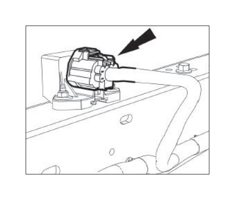
a. Disconnect the fuel pump control module electrical connector. It is located on the frame rail above the spare tire.
b. Start the engine and allow it to idle until it stalls.
c. After the engine stalls, crank the engine for approximately 5 seconds to make sure the fuel rail pressure has been released.
d. Turn the ignition switch to the OFF position.
3. Using an 8 mm wrench, disconnect the (-) negative and ( ) positive connections to the battery and remove the battery from the vehicle.
Before continuing, refer to the CALKIT included with your ROUSHcharger kit. Determine the PCM fl ash method you will be using. If performing the PCM fl ash yourself or at a preferred ROUSH dealer, proceed to step 6. If sending the PCM to ROUSH for a ROUSH performed PCM fl ash, continue with steps 4 and 5.
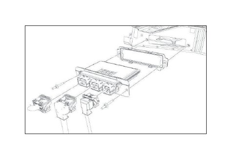
4. Remove the PCM cover by undoing the two (2) crimp nuts retaining the cover to the studs.
5. Undo the three (3) PCM connectors by lifting the grey levers over the connector back shell and lifting the connectors from their sockets. Remove the PCM by removing the two (2) studs and pulling the PCM forward and lifting out of the engine compartment. Follow the instructions on the next page as soon as possible to help minimize the amount of time you are without a PCM.
IMPORTANT: Be sure to write your VIN number and phone number on the PCM using a permanent marker. Please do this in the case that we need to contact you for additional vehicle information.
INSTRUCTIONS FOR RETURNING THE PCM TO ROUSH FOR CALIBRATION
Outlined below are the instructions for returning your stock powertrain control module (PCM) to ROUSH Performance Products so we can install our calibration to make the engine run properly with the new components. Please complete the “Base Limited Warranty Registration” card and include it, along with the PCM, the “Optional Roush PCM Flash” request document, and the “Voucher Card”. Once we receive your PCM, we will reprogram and return it back to you the same day for next-day delivery. Operating your engine without our calibration will result in engine damage or failure and will void all warranty.
NOTE: It is important to reinstall the PCM in the vehicle it came from to prevent setting a trouble code and having to relearn the anti-theft code which can only be performed using specialized Ford Service Bay tools.
• If you haven’t already done so, write your vehicle identifi cation number (VIN) and phone number on the PCM using a permanent marker.
• Using bubble wrap, or another appropriate packing material, wrap and package the PCM to help prevent it from being damaged during shipping.
• Place the wrapped PCM in an appropriate shipping box.
• Complete the “Warranty Registration Card” (1150-TVSCALWC).
• Complete the “Optional ROUSH PCM Flash” request document (PCM-FLASHDOC) and attach the fl ash Voucher Card (P1150-P2) to the document.
• Include the “Warranty Registration Card”, “Optional ROUSH PCM Flash” document, and the Voucher Card in the shipping box, along with the PCM.
• Ship the PCM and contents to: ATTN: PCM FLASH 39555 Schoolcraft Rd Plymouth, MI 48170
Upon receipt of the PCM, a customer service representative will contact you to arrange payment. Once you receive your ROUSH-fl ashed PCM, reverse steps 4 and 5 for PCM installation.
6. With the engine cool, remove the cap on the engine coolant degas reservoir bottle and the upper radiator fi ll cap. Drain the coolant using the petcock located on the lower passenger side of the radiator. Tighten the petcock once the engine coolant has been drained.
TIP: Connect a 3/8" hose to the drain fi tting next to the petcock and run into a clean drain pan or bottle. Use a fl at-blade screwdriver to open petcock and allow coolant to drain out of the fi tting.
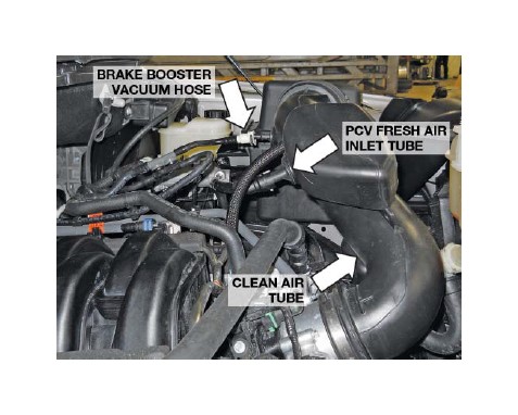
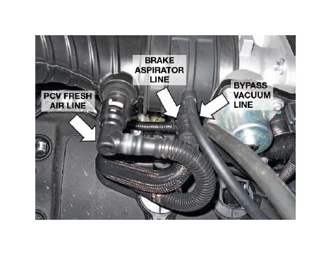
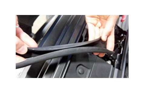
7. Disconnect the PCV fresh air inlet tube from the left-hand (driver side) cam cover and the clean air tube. Remove hose from vehicle. Disconnect the brake booster vacuum hose from the clean air tube. Disconnect the clean air tube from the throttle body and the upper airbox lid. Remove the clean air tube from the vehicle. Neither of these components will be reused.
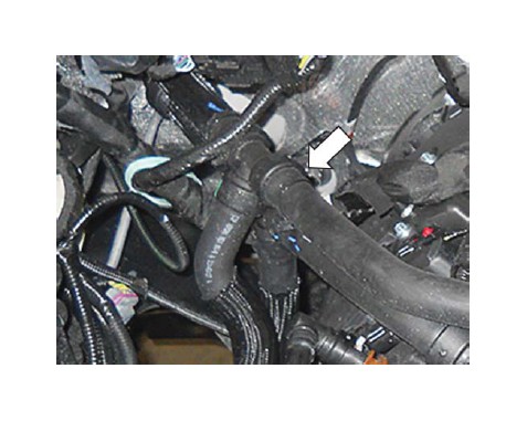
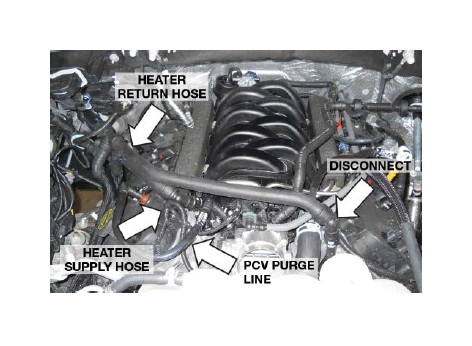
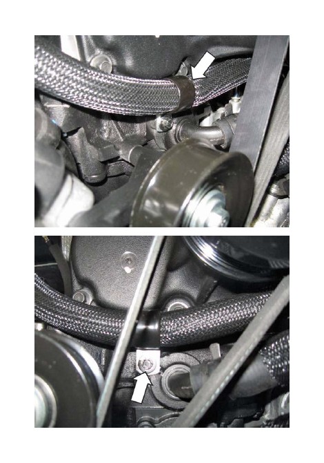
8. Disconnect the heater supply hose quick connect fi tting on the front passenger side of the engine. Position this hose aside.
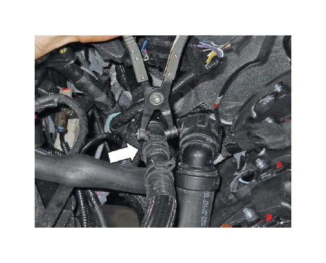
9. Cut the heater return hose at the plastic tee fi tting at the front passenger side of the engine. Disconnect the heater return hose quick-connect fi tting on the front driver side of the engine and remove the cut hose. It is not reused.
10. Using a suitable tool, cut the clamp from the T-fi tting holding the short hose just cut. Remove the hose.
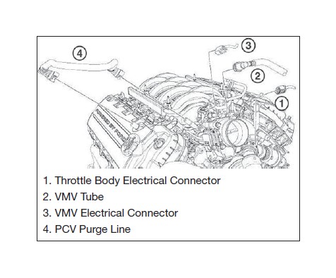
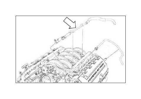
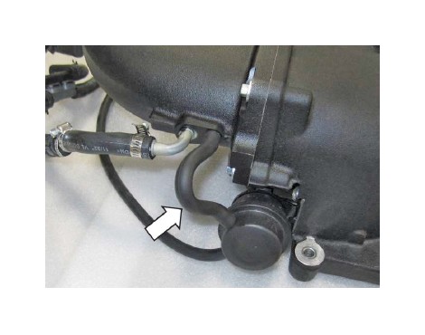
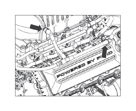
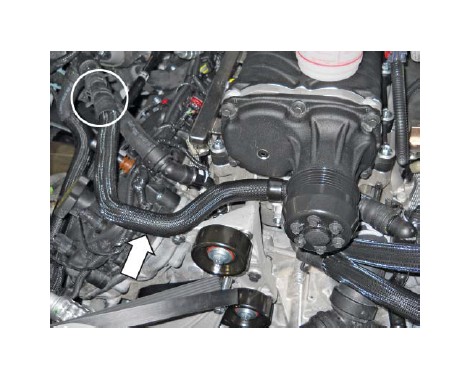
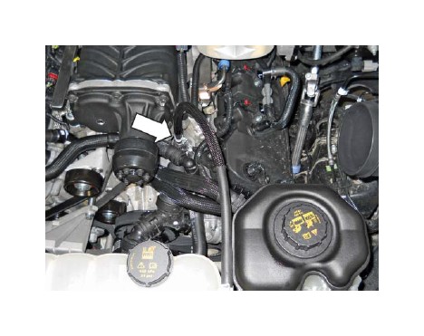
11. Remove the PCV purge line from the intake manifold and passenger side cam cover. This line will not be reused.
12. Disconnect the white quick-connect fi tting from the brake booster.
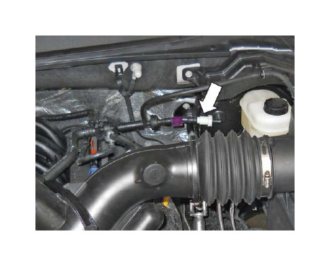
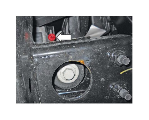
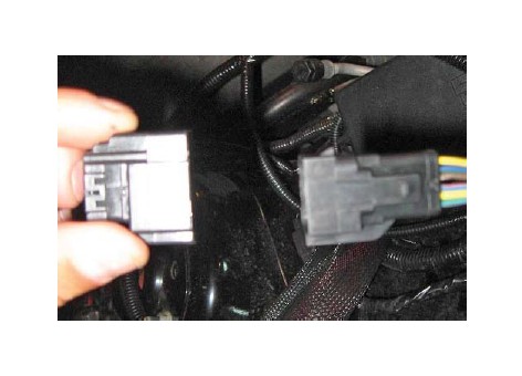
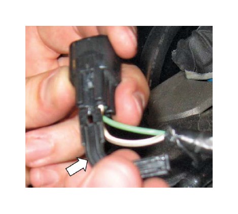
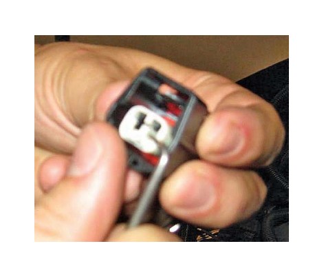
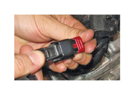
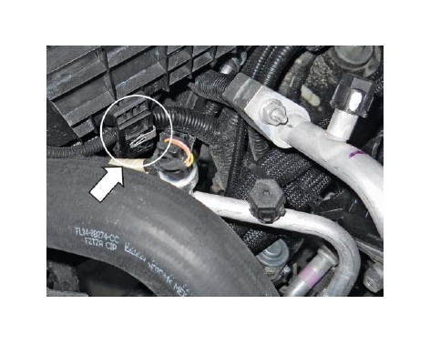
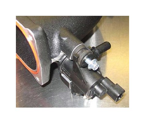
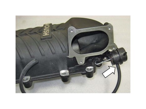
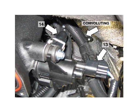
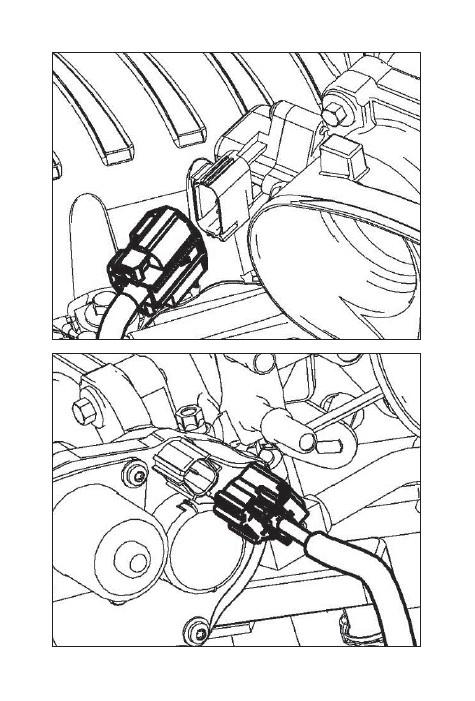
13. Disconnect the throttle body electrical connector. (Pull the red locking tab back; press the black release tab to disengage the lock.) Refer to fi gure shown.
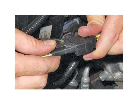
14. Disconnect the VMV (evaporative emission canister purge valve) tube and electrical connector. Remove the VMV tube retainer from the fuel rail and fuel supply line.
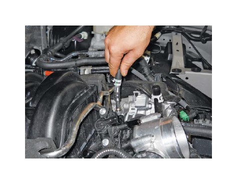
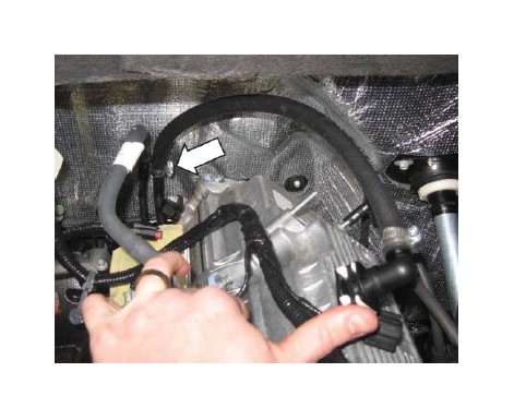
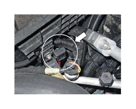
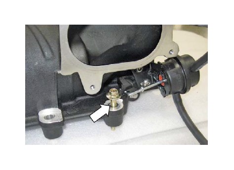
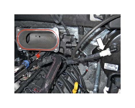
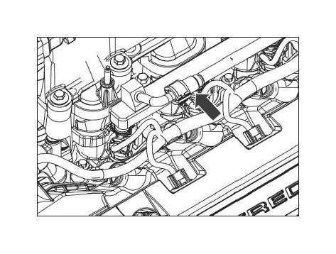
15. Disconnect the fuel supply line from the fuel rail. Refer to fi gure shown below.
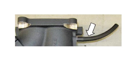
16. Disconnect the brake booster vacuum hose from the intake manifold. This port is located directly behind the throttle body.
17. Remove the 3/8” engine coolant degas hose from the connection at the engine and place the loose end of the hose to the side for later connection.
18. Remove and discard the LH and RH fuel rail insulators. Disconnect the eight (8) fuel injector electrical connectors.
19. Remove the four (4) fuel rail bolts. These bolts will be reused. NOTE: It is not necessary to remove the fuel rail from the intake manifold assembly.
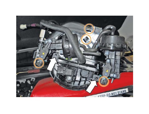
20. Remove the remaining six (6) intake manifold mounting bolts. Lift up and move the manifold forward enough to access and remove the retaining pins attaching the wiring harness at the back of the manifold. Remove the intake manifold and fuel rail assembly from the vehicle. This hardware will not be reused.

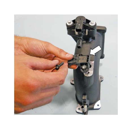
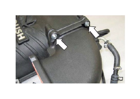
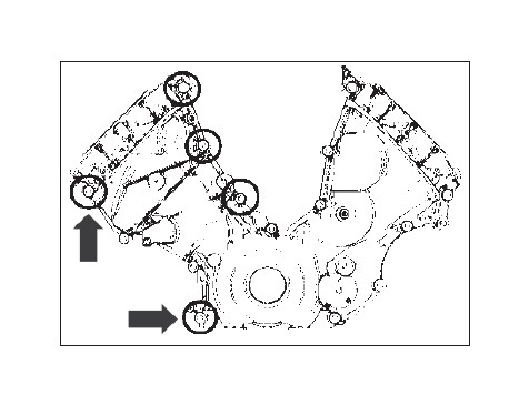
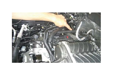
21. Carefully disconnect the four (4) harness connectors (circled) and from the rear of the intake manifold. Remove the two (2) pushpins attaching the wiring harness to the manifold; retain the pushpins for reuse at installation.
22. Clean the intake mounting surfaces and apply tape over the open intake ports to prevent engine contamination.
23. Disconnect the eight (8) coil plug electrical connectors and remove the eight (8) coils from the vehicle by removing the bolt securing them to the cam covers.
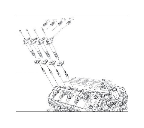
24. Remove the factory spark plugs and install the new spark plugs (CYSF 12YP) provided with the kit. Torque to 14 Nm.
25. Re-install the coil on plugs and torque to 6 Nm. Connect the electrical connector to the coil on plugs in eight (8) places.
26. Disconnect both ends of the upper radiator hose and remove from the vehicle.
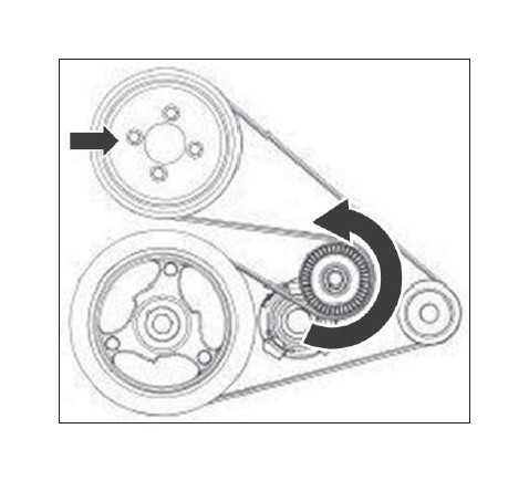
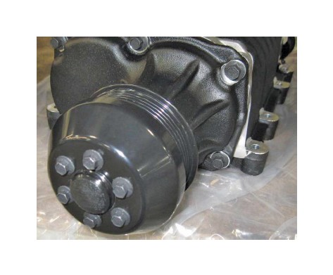
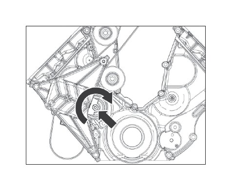
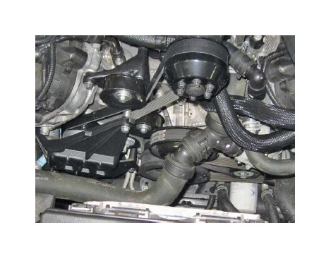
27. Loosen the four (4) water pump pulley bolts, and then remove the front engine accessory drive (FEAD) belt. Rotate the FEAD tensioner counterclockwise to release the belt tension and remove the belt.
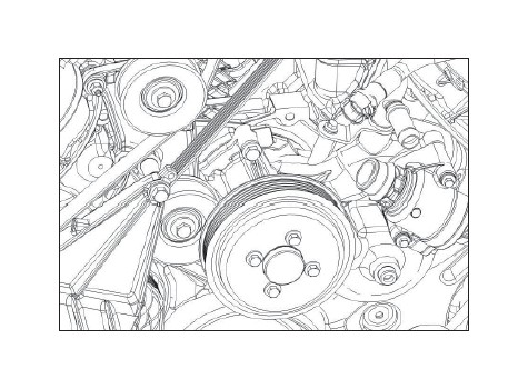
28. Remove the four (4) bolts securing the water pump pulley to the engine.
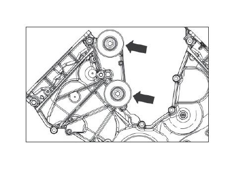
29. Cut the A/C compressor belt and remove the belt from the engine. Then remove the tensioner and the idler; these parts will not be re-used.
SECTION B – MODIFICATIONS
The following section will guide you through the required modifi cations of existing components and build up of the assemblies used to complete the installation. With the exception of the wiring modifi cations and the A/C compressor clutch assembly R&R, all of this work can be performed away from the vehicle.
A/C COMPRESSOR PULLEY REPLACEMENT
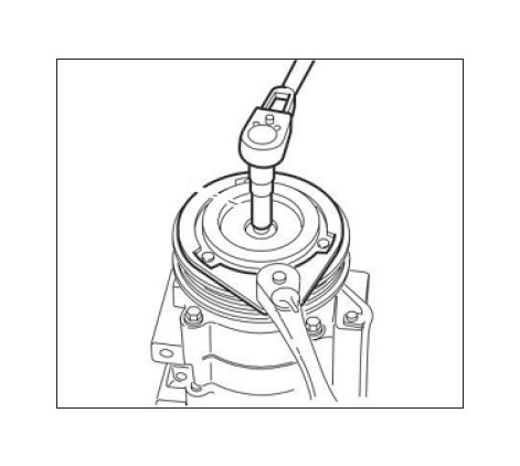
A/C Clutch Disc and Hub Bolt Removal
1. Using the A/C Clutch Holding Tool, hold the A/C clutch disc and hub.
2. Remove the A/C clutch disc and hub bolt.
3. Remove the A/C clutch disc and hub.
4. Remove the A/C compressor pulley snap ring.
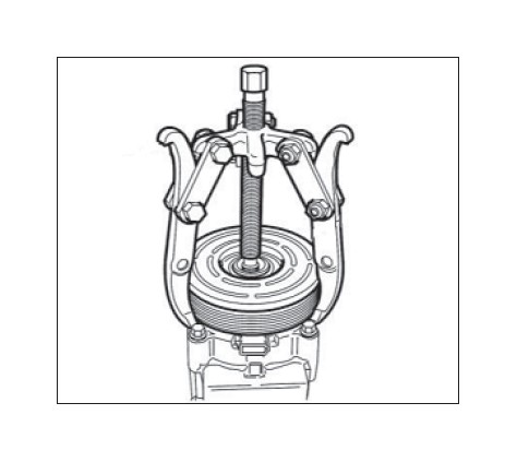
Compressor Pulley Removal
NOTICE: Do not use air tools. Damage to the air conditioning (A/C) clutch pulley or A/C compressor may result.
1. Install the Compressor Pulley Remover.
2. Remove the A/C compressor pulley.
Compressor Pulley Installation
NOTE: The supplemental kit includes the electro magnet as well. Installation of the electro magnet is not required. Save or discard the electro magnet.
1. Clean the A/C pulley mounting surfaces.
NOTE: The A/C compressor pulley is a tight fi t on the A/C compressor. It must be correctly aligned during installation.
2. Install the A/C compressor pulley.
3. Install the A/C compressor pulley snap ring with the bevel side out.
4. Place one nominal thickness A/C clutch disc and hub spacer inside the clutch hub spline opening.
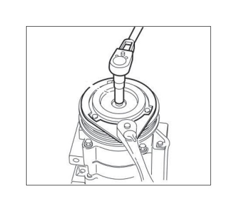
A/C Clutch Disc and Hub Bolt Installation
1. Using the A/C Clutch Holding Tool, hold the A/C clutch disc and hub.
2. Tighten the bolt to 14 Nm.
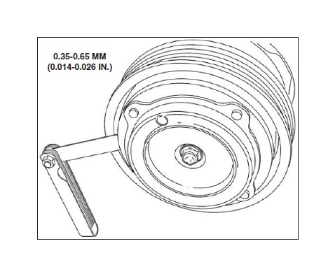
3. Measure and adjust the clutch air gap at three (3) spaces by removing or adding A/C clutch disc and hub spacers.
CRANKSHAFT PULLEY REPLACEMENT
NOTE: After crankshaft pulley installation, it will be necessary to relearn the misfi re profi le correction using RDT. Refer to the RDT-CALIM included with your ROUSHcharger kit.
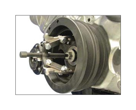
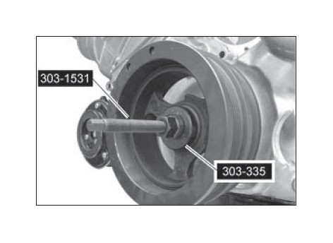
Pulley Removal
1. Loosen the crankshaft pulley bolt and washer.
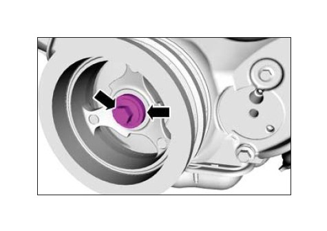
2. Using a 3-Jaw Puller and the crankshaft pulley bolt, remove the crankshaft pulley. Discard the crankshaft pulley bolt.
Pulley Installation
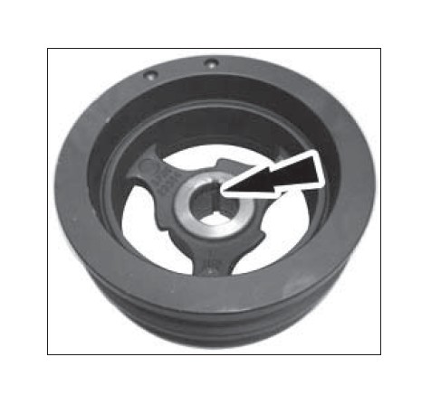
NOTE: If not secured within 5 minutes, the sealant must be removed and the sealing area cleaned with silicone gasket remover and metal surface prep. Failure to follow this procedure can cause future oil leakage.
1. Apply silicone gasket and sealant to the Woodruff key slot in the crankshaft pulley.
2. Lubricate the crankshaft pulley sealing surface with clean engine oil prior to installation.
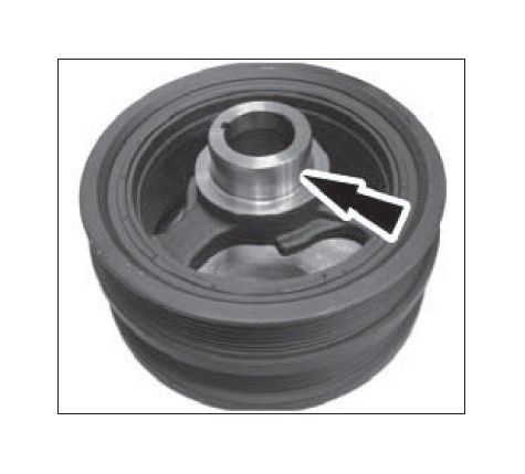
3. Using a suitable Damper Installation Tool, install the crankshaft pulley.
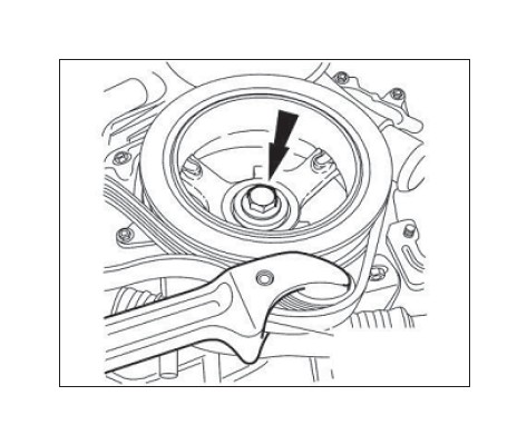
4. Using the Strap Wrench, install a new crankshaft pulley bolt and the original washer. Tighten the bolt in four (4) stages:
• Stage 1: Tighten to 140 Nm.
• Stage 2: Loosen 360 degrees.
• Stage 3: Tighten to 100 Nm.
• Stage 4: Tighten an additional 90 degrees
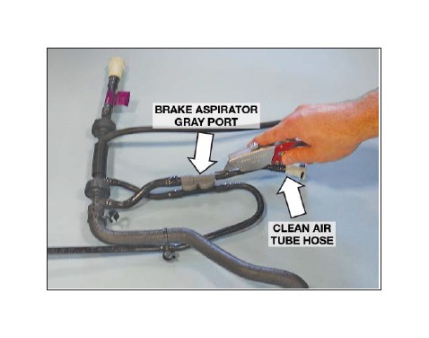
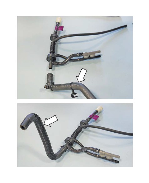
BRAKE BOOSTER HOSE AND ASPIRATOR ASSEMBLY MODIFICATION
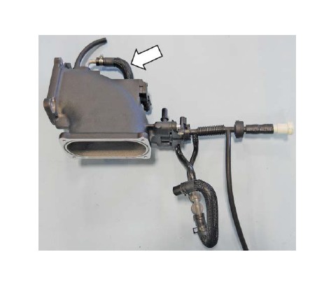
1. With the brake booster hose and aspirator assembly removed from the intake manifold, locate the stock clean air tube hose with the quick-connect fi tting. Carefully cut the hose at the grey port barb as shown and remove the hose and fi tting from the brake aspirator. The removed hose and fi tting are not reused.
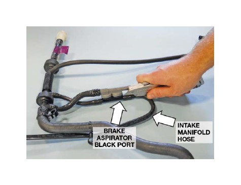
2. Carefully cut and remove the stock intake manifold hose from the black port of the brake aspirator. The removed hose is not reused.
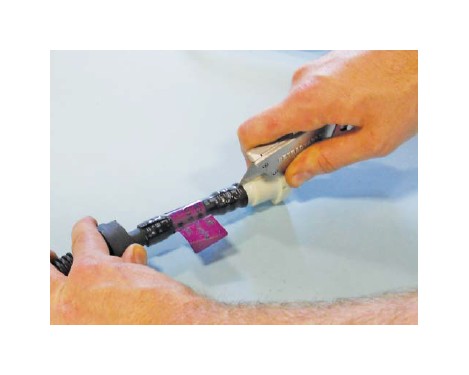
3. Slide the clamp away from the check valve and the factory aspirator-to-throttle body hose. Replace the removed hose (top) with the new formed EPDM aspirator-to-throttle body spacer hose (1115-9D692) (bottom) and install it on the brake aspirator assembly. Use the original clamp to secure the hose to the assembly.
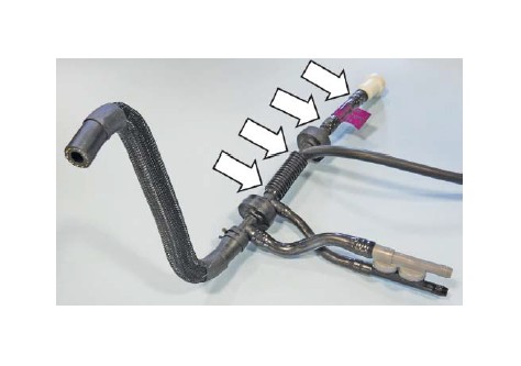
4. Shorten the brake booster hose as follows. Carefully cut the two (2) nylon hose sections over the four (4) barbed port ends of the coupling and check valves in the areas shown. Remove and discard the hose sections.
5. Replace the removed hose sections with two (2) sections of brake aspirator 4x4 hose (1115- 9D693). This shortens the brake booster hose line by approximately 2 inches.
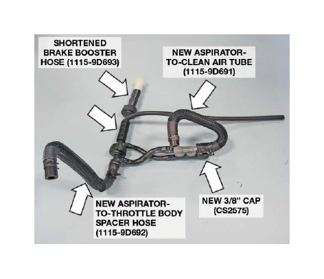
6. Complete the hose assembly by installing the new formed EPDM aspirator-to-clean air tube (1115- 9D691) on the grey port of the aspirator. Then, install the new 3/8" cap (CS2575) on the black aspirator port.
VMV HOSE MODIFICATION
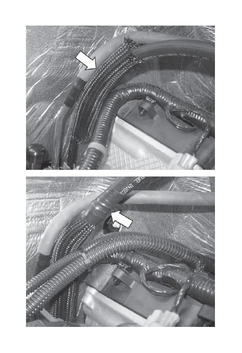
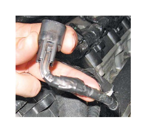
1. Locate the fuel vapor hose beside the fuel supply line. At the joint where the tube transitions from steel to plastic, cut the VMV line in a vertical direction and remove the covered plastic portion from the steel line fi xed in the vehicle.
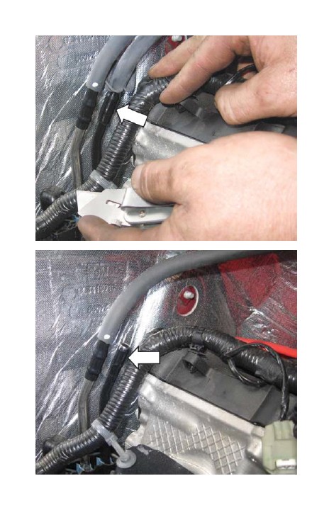
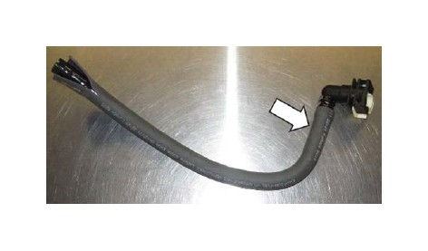
2. With the line removed from the vehicle, carefully cut along the opposite end of the hose where the fi tting is inserted and remove the quick connect fi tting from the hose.
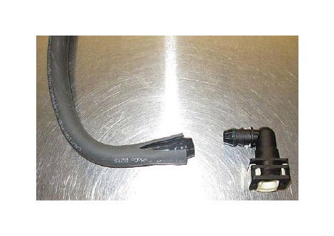
3. Install the quick connect fi tting into one end of the new VMV hose (27004) and secure using one (1) worm drive clamp (62003).
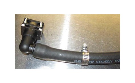
4. Place the second worm drive clamp (62003) over the opposite end of the new VMV hose and install onto the steel line. Position the clamp so the screw (drive) side is closest to the cylinder head and tighten the clamp.
5. Cut a six-inch piece of the protective convolute tubing from that supplied in the kit and insert it over the quick-connect fi tting. Position the tubing so it covers the clamp between the fuel supply line and the VMV line and tape the ends of tubing to keep it in position.
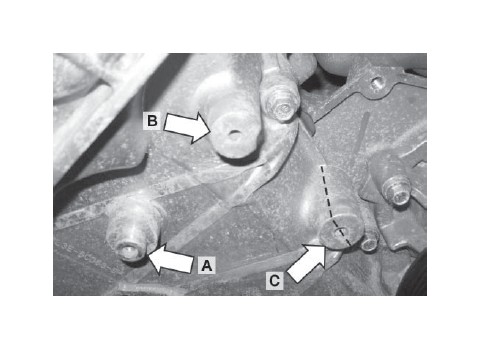
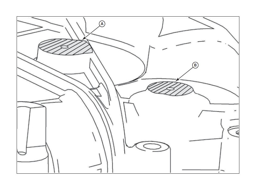
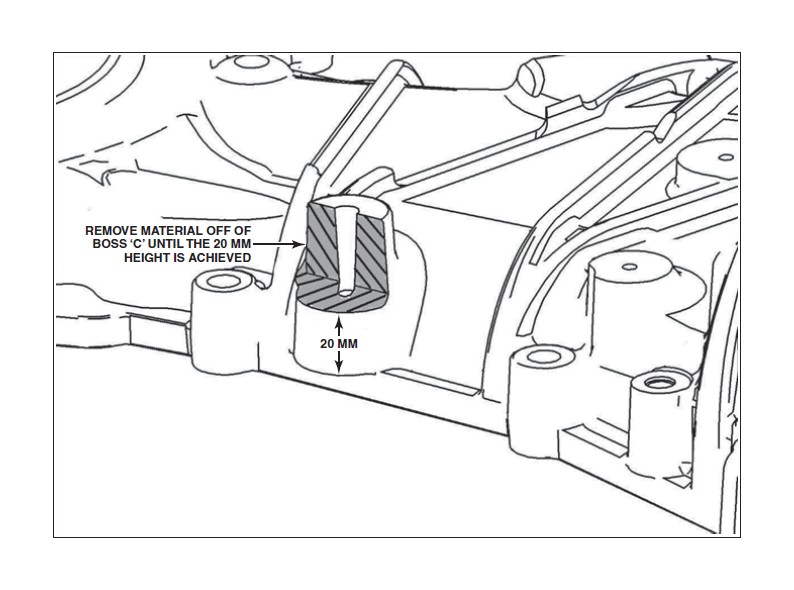
FRONT COVER MODIFICATION
Using a grinder or cut-off wheel, modify the front cover in the areas shown. The two (2) bosses located at A and B need to be reduced in height such that they are fl ush, or 2 mm off of the front cover surface. The boss located at C needs to be reduced in height and cut in half.
Cross-hatched surfaces A and B must be lower than or equal to this rib height (2 mm).
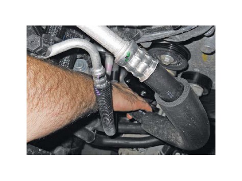
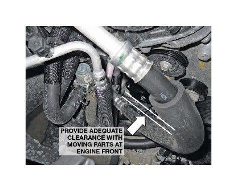
A/C LINE MODIFICATION
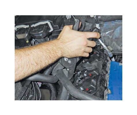
Grab the A/C line as shown and pull forward to bend the line slightly to reposition it for more clearance at the front of the engine.
NOTE: You should be able to pass a 1/4" drive extension through this area.
TPS/ETC WIRING
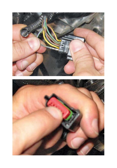
1. Locate the throttle position sensor (TPS) connector and harness at the front of the passenger side cylinder head. Use a proper depinning tool to remove the connector from the harness.
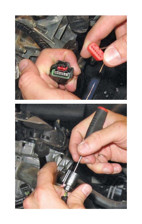
2. Depress the locking tab and separate the “empty” female 1 x 6 connector from the new TPS/ETC extension harness (131114A595). It will be used in the next step.
3. Populate the new connector such that the yellow with violet wire is in position 1, the blue with green wire is in position 2, the brown wire is in position 3, the blue with orange wire is in position 4, the yellow wire is in position 5 and the green with violet wire is in position 6. Install the red plastic lock into the connector to secure the wires in place.
4. Connect the TPS/ETC extension harness to the newly installed connector. The wire colors on each side of the connector pair should align. Route the harness along the main wiring harness to the rear of the driver side cam cover. Use tape or zip ties to secure the extension harness to the main harness.
CANISTER PURGE VALVE WIRING
1. Locate the canister purge valve electrical connector at the front of the passenger side cylinder head. Remove and discard the 90-degree wire retainer. Use a proper de-pinning tool to remove the connector from the harness. Discard the retainer.
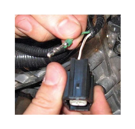
2. Depress the locking tab and separate the “empty” female 1 x 2 connector from the canister purge valve extension harness (13119G866). This connector replaces the connector removed in the previous step. Carefully pull the white locking tab forward to allow wires to be installed into the connector. Populate the new connector such that the white with brown wire is in position 1 and the green wire is in position 2. Depress the white locking tab to secure the wires.
3. Connect the canister purge valve extension harness to the newly installed connector. The wire colors on each side of the connector pair should align. Route the harness along the main wiring harness to the rear of the driver side cam cover. Use tape or zip ties to secure the extension harness to the main harness.
INTERCOOLER PUMP WIRING
1. Install the M6 J-clip found in Hardware Kit E (1115-TVSHKE) over the hole in the front corner of the battery box as shown.
2. Install the relay and fuse from the intercooler pump wiring harness (1315-8W501) onto the J-clip. Use the one (1) M6 x 1.0 x 20 bolt (W500214-S437) from the Hardware Kit E (1115-TVSHKE) to secure the relay and fuse to the J-clip. Torque the bolt to 5 Nm.
3. Route the black ground wire from the I/C pump harness along the chassis and up the radiator support to the battery negative cable terminal. Remove the ground stud nut from the cable terminal and install I/C pump black ground wire eyelet. Reinstall the nut to secure the factory ground and I/C grounding eyelet to the cable terminal; torque the nut to 10 Nm. Install a zip tie to secure the harness to the battery cable.
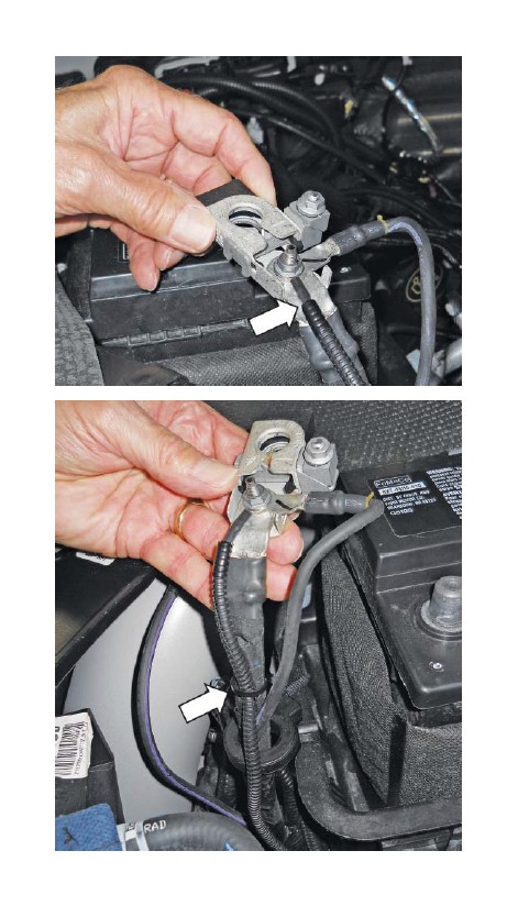
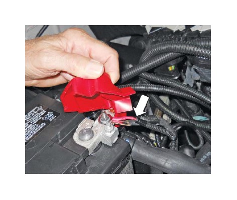
4. Route the red wire (part of the intercooler pump wiring harness installed above) to the positive terminal of the battery cable. Remove the nut from the positive terminal and install the red wire eyelet. Reinstall the nut onto the terminal and torque to 10 Nm.
5. Route the single wire with the two (2) electrical connectors along the factory engine harness to the rear of the driver side cylinder head. Connect these two (2) connectors inline with the driver side radio capacitor. The single connector will be routed to the intercooler pump in Section D of this manual.
AIR CHARGE TEMPERATURE (ACT) WIRING
1. Locate the IMRC sensor connector (light grey) at the rear of the passenger side cylinder head.
2. Connect the IMRC sensor connector into the ACT wiring harness (1315-12A690).
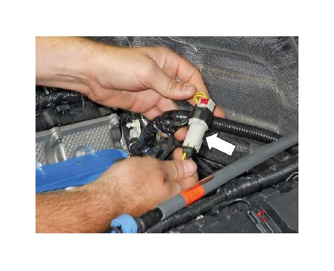
3. Route the extension wiring harness across the engine to the passenger side cylinder head.
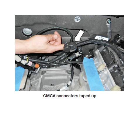
4. Wrap electrical tape around the two (2) blue CMCV connectors at the rear of the cylinder head as shown.
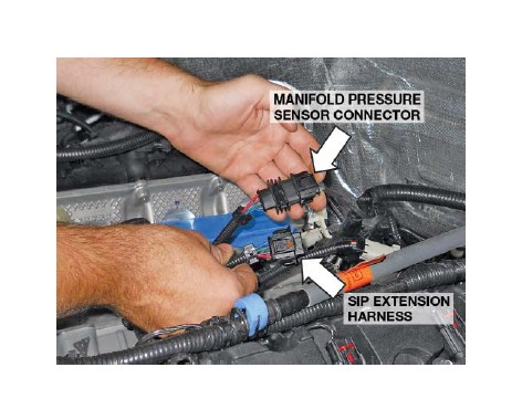
SUPERCHARGER INLET PRESSURE (SIP)WIRING
1. Locate the manifold pressure sensor connector at the rear of the passenger side cylinder head.
2. Connect the SIP extension harness (1115-9D930) to the manifold pressure sensor connector.
3. Route the extension wiring harness to the driver side cylinder head.
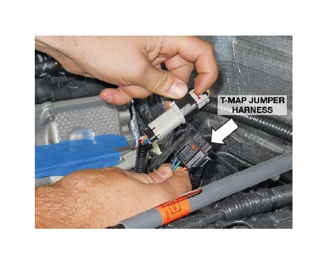
T-MAP WIRING
1. Locate the IMRC sensor connector (light grey) at the rear of the driver side cylinder head.
2. Connect the IMRC sensor connector into the T-MAP jumper harness (1115-9A588).
3. Route the extension wiring harness along the back of the driver side cylinder head.
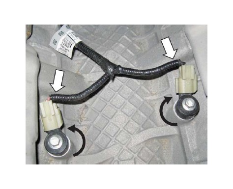
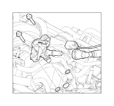
KNOCK SENSOR ORIENTATION ADJUSTMENT
1. Loosen the two (2) bolts which retain the knock sensors to the engine block and rotate the RH and LH knock sensor toward the RH and LH cylinder heads respectively. In order to do so, fi rst remove the 90-degree plastic wiring retainer clipped to the connector and taped to the wiring convolute. Torque the knock sensor bolts to 25 Nm.
SECTION C – SUBASSEMBLY
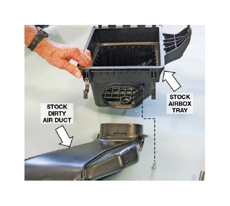
AIR BOX ASSEMBLY
1. With the stock dirty air duct and airbox tray assembly removed from the vehicle, remove the bolt securing the duct in place on the airbox tray. Separate the tube from the airbox; the airbox tray will not be reused.
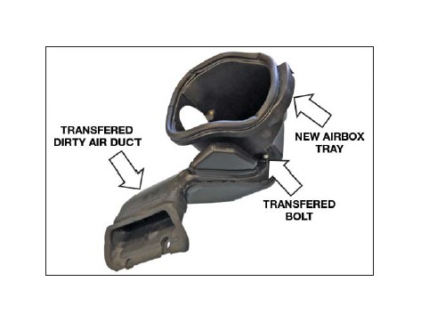
2. Transfer and assemble the stock dirty air duct to the new airbox tray (1115-9A612). Install the factory bolt to secure the duct in place. Torque the bolt to 3 Nm.
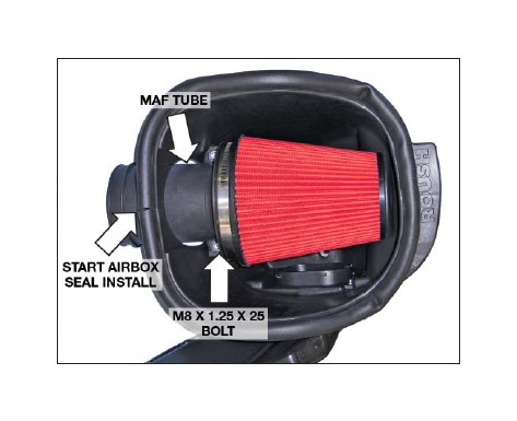
3. Install the air fi lter (131550-9601R-AA) on the MAF tube (111550-12B579) and secure it with the supplied clamp. Torque the clamp to 3 Nm.
4. Insert the MAF tube and fi lter into the airbox tray and secure in place with two (2) M8 x 1.25 x 25 bolts (W500224-S437). Torque the bolts to 10 Nm.
5. Install the airbox seal (1115-9B624) on the airbox fl ange starting at the position shown and secure it with the supplied clamp. Torque the clamp to 3-5 Nm.
CLEAN AIR TUBE ASSEMBLY
1. Using two (2) hose clamps (R07130015-13), install the cuff, T-body-to-CAT (1115SC-9B662) and the coupler, MAF-to-CAT (1115SC-9B661) on the respective ends of the clean air tube (1115SC- 9B660) as shown.
2. Install the 5’8" PCV fresh air fi tting (1311-9N285) and grommet (1150-5/8GRMT) on the clean air tube.
3. Install the bypass vacuum fi tting (383004-S) and 3/8" x 3/8" straight connector (P2233A) in the respective ports on the T-body-to-CAT cuff.
INTERCOOLER LOW TEMPERATURERADIATOR (LTR)
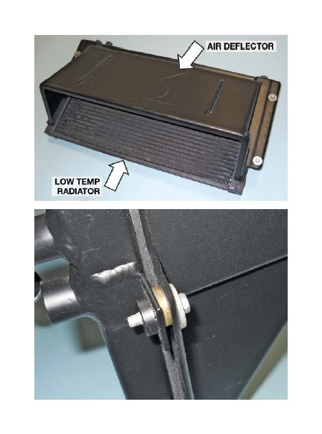
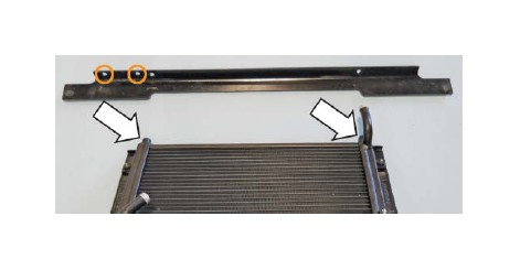
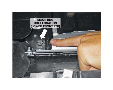
1. Position the low temp radiator (LTR) (1115-8K229) on your work surface with the inlet and outlet ports facing down as shown.
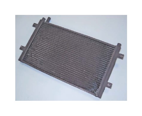
2. Apply foam tape cut from the bulk tape (1115-8K229FOAM) supplied in Hardware Kit F (1115-TVSHKF) to the top and two (2) sides of the LTR.
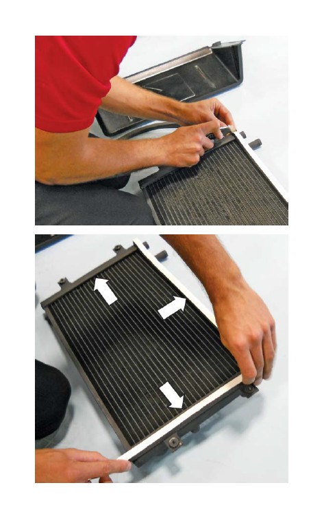
3. Remove the protective backing from the foam tape. Place the LTR air defl ector (1115-5K235) in position over the LTR using care to align the mounting holes. Install the four (4) M6 x 20 bolts (W500214-S437) to attach the defl ector to the LTR. Torque the bolts to 10 Nm.
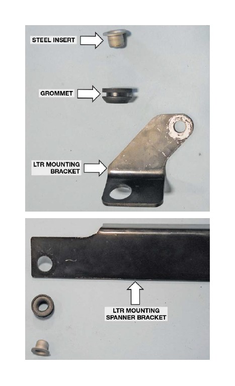
4. Insert a grommet (R07060107-13) and a steel grommet insert (R0706108-13) into the vehicle frame mounting holes of the two (2) LTR mounting brackets, lower LH (1115-8K243) and lower RH (1115-8K242) and the LTR mounting spanner bracket (1115-8K241). These can be found in Hardware Kit F (1115-TVSHKF).
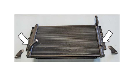
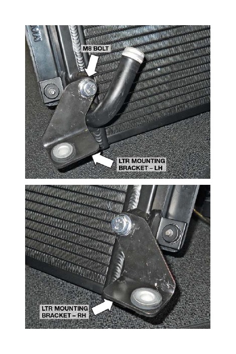
5. Position the two (2) LTR lower mounting brackets into place on the LTR. Loosely install one (1) M8 x 1.25 x 20 bolt (90386A108) from Hardware Kit F through the non-grommet/insert bracket hole of each bracket and secure to the threaded boss on the LTR (two [2] places).
6. The LTR spanner bracket (1115-8K241) attaches to the two (2) threaded bosses located at the upper end the LTR. Do NOT attach the bracket at this time. The spanner bracket must be installed on the vehicle before the LTR assembly is attached. This will be done later in SECTION D — INSTALLATION.
NOTE: The intercooler pump (F8YH-8501) will be installed on the LTR spanner bracket after the bracket and the LTR have been installed on the vehicle.
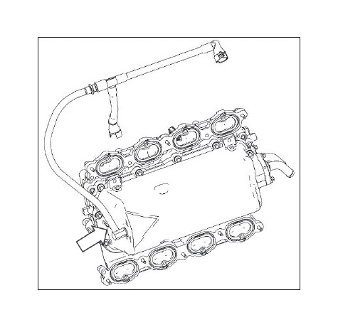
INTAKE MANIFOLD BUILD UP
1. Remove the fuel charging assembly (13119H487) from the packaging.
2. Attach the rubber hose from the PCV purge hose (13116K817) to the bubbler fi tting (3/8" barb) on the bottom of the fuel charging assembly and secure it with the supplied clamp.
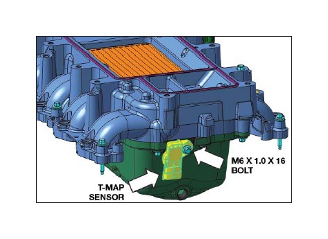
3. Install the T-MAP sensor (BV6Z-9F479) on the lower intake manifold housing and secure with an M6 x 1.0 x 16 bolt (W500013-S307) found in Hardware Kit B (1115-TVSHKB). Torque bolt to 10 Nm.
THROTTLE BODY SPACER ASSEMBLY
1. Remove the evaporative emission canister purge valve from the stock intake manifold.
2. Install the valve into the new throttle body spacer (1115-9A589) and secure using the two (2) M6 x 31 bolts (R18020009-00) found in Hardware Kit B (1115-TVSHKB). Torque bolts to 10 Nm.
3. Connect the supercharger boost bypass actuator hose (short 4" hose – R18140001) to the straight fi tting on throttle body spacer.
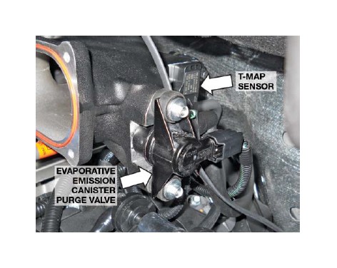
4. Remove the T-MAP sensor from the stock intake manifold.
5. Install the T-MAP sensor on the throttle body spacer and secure with an M6 x 1.0 x 16 bolt (W500013-S307) found in Hardware Kit B (1115-TVSHKB). Torque bolt to 10 Nm.
6. Connect the modifi ed brake aspirator assembly to the 90-degree elbow on the throttle body. This will be connected to the brake booster once the throttle spacer is installed.
FUEL RAIL ASSEMBLY
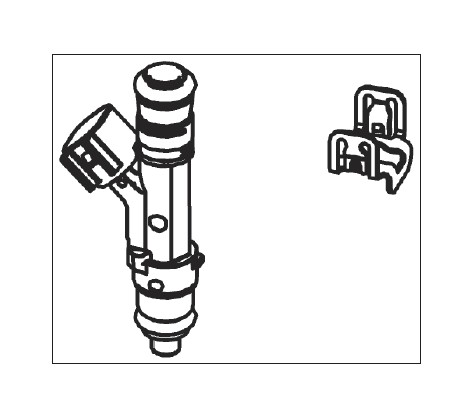
1. Carefully install the eight (8) new anti-rotation fuel injector clips (13119C995) onto the fuel injectors (13119F593K) provided.
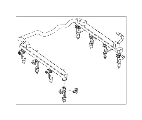
2. Apply assembly lubricant to the injector O-rings and install the injectors into the new fuel rail (13119F792). NOTE: Verify that the anti-rotation clips are properly aligned and fully engaged into the fuel rail injector cups.
SECTION D – INSTALLATION
The following section will guide you through the fi nal installation of the kit into the vehicle. If you need to stop during any part of the installation, make sure you cover any open ports in the cylinder heads or intake manifold to prevent foreign material from contaminating your engine.
INTAKE MANIFOLD AND SUPERCHARGER INSTALLATION
1. Remove the tape from the cylinder heads and clean the cylinder head-to-intake manifold mating surfaces.
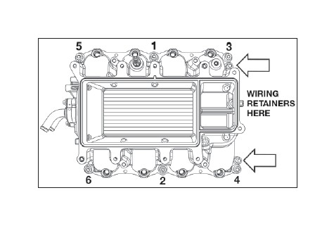
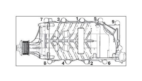
2. Install the intake manifold using six (6) M6 x 1.0 x 40 mm bolts (R18020004) found in Hardware Kit B (1115-TVSHKB). Tighten the fasteners in two stages with the sequence shown. Stage 1; torque bolts to 10 Nm. Stage 2; tighten bolts an additional 45 degrees. Reinstall the engine wiring harness retention clips at the rear of the intake manifold.
3. Lubricate the fuel injector O-rings with assembly lubricant. Install the fuel rail and injectors into the intake manifold using the take-off bolts. Be sure each injector is properly seated into the intake manifold. Tighten the fasteners in two stages with the sequence shown. Stage 1; torque bolts to 10 Nm. Stage 2; tighten bolts an additional 45 degrees.
4. Connect the eight (8) fuel injector electrical connectors.
5. Connect the IMRC-MAP wiring harness to the T-MAP sensor installed on the lower intake manifold housing.
6. Connect the ACT wiring harness to the ACT sensor on the passenger side intake manifold.
7. Remove the supercharger assembly (1311H- 6F066) from the protective packaging and place on a workbench or solid, fl at surface. Use extreme caution as the bypass actuator housing is fragile. Remove the protective shipping covers.
8. Install the 75 mm supercharger pulley (1311-6K75-AA) onto the hub of the supercharger using the six (6) M6 x 1.0 x 16 bolts (W500013- 5307) found in Hardware Kit B (1115-TVSHKB). Apply a small amount of blue thread locking compound to the bolts, and torque to 10 Nm.
9. Connect the supercharger bypass reference vacuum line (23.5" length of hose R18140001) to the bottom fi tting on the supercharger bypass actuator. Route this underneath the VMV and fuel line.
10. Insert one (1) of the M8 x 55 fasteners (N808130 S437) found in Hardware Kit B (1115-TVSHKB) into the mounting hole directly below the supercharger inlet.
11. Install the throttle body spacer-to-supercharger gasket (R07060153-13) between the throttle body spacer assembly and the supercharger and mount the spacer using four (4) M6 x 31 bolts (R18020009-00). These parts can be found in Hardware Kit B (1115-TVSHKB). Torque the fasteners to 10 Nm.
12. Connect the boost bypass hose from the throttle body spacer to the top port of the supercharger bypass actuator.
13. With the help of an assistant, carefully place the supercharger and throttle spacer on top of the intake manifold, sliding it underneath the cowl into position. Ensure that the supercharger is fully seated on the intake mounting dowels.
NOTE: Make sure the bolt mounted below the throttle body spacers does not catch on anything as you slide the supercharger into position.
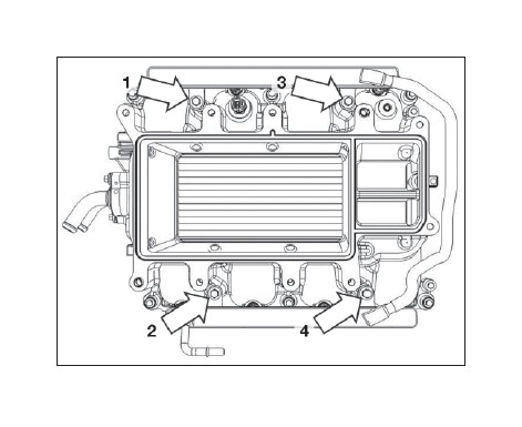
14. Install the remaining nine (9) M8 x 55 fasteners (N808130-S437) provided in Hardware Kit B (1115-TVSHKB) into the mounting holes. Torque fasteners in three (3) stages: •
Stage 1: Tighten fasteners to 10 Nm in the sequence shown.
• Stage 2: Tighten fasteners to 20 Nm in the sequence shown.
• Stage 3: Tighten fasteners to 30 Nm in the sequence shown.
Access bolt hole number 10 by reaching behind the supercharger from the passenger side of the vehicle.
15. Connect the short hose quick connect to the 90-degree fi tting on the brake booster. NOTE: It is recommended that some form of abrasionresistant sleeve or convoluting be installed on the brake aspirator lines to prevent chaffi ng of components.
Use care in routing the brake booster hose to avoid crushing the fuel line.
16. Connect the evaporative emission canister purge valve electrical connector.
17. Connect the new SIP extension harness (1115- 9D930) to the TMAP sensor on the throttle body spacer.
18. Connect the new evaporative emission canister purge valve hose quick-connect fi tting to the relocated purge valve on the throttle body spacer.
19. Connect the fuel inlet line to the fuel rail. Secure the lock into position.
20. Connect the PCV purge line (13116K817) to the PCV valve on the passenger side cam cover and the port on the supercharger.
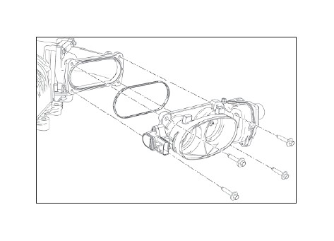
21. Install the throttle body gasket (R07060153-13) in the throttle body spacer. Use four (4) M6 x 1.0 x 31 mm bolts (R18020009-00) to secure the throttle body assembly (R07060150-13) to the spacer. Torque bolts to 10 Nm. These can be found in Hardware Kit B (1115-TVSHKB).
22. Connect the TPS and ETC throttle body electrical connectors.
FEAD ASSEMBLY
NOTE: If installing on 2014 F-150, install the components included in the optional supplemental FEAD kit before proceeding.
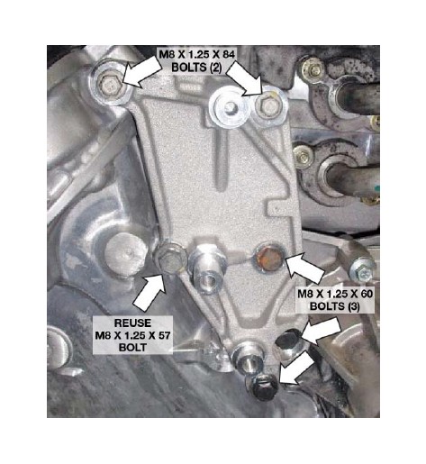
1. Remove the four (4) bolts and one (1) stud from the front cover as shown.
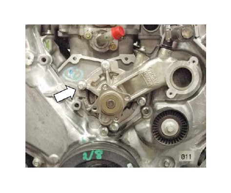
2. Remove and discard the 10 mm water pump fastener shown below.
3. Install the upper FEAD bracket (1314-8B653U) using one (1) M8 x 1.25 x 57 bolt that was removed in the previous step, three (3) M8 x 1.25 x 60 bolts (11127083) and two (2) M8 x 1.25 x 84 bolts (W704752-S437) from Hardware Kit C (1315-TVSHKC). Torque bolts to 20-30 Nm.
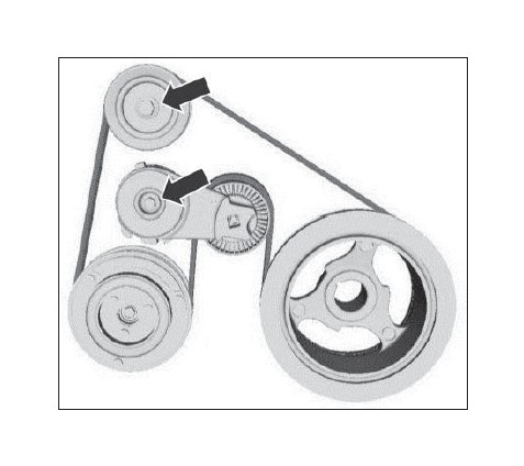
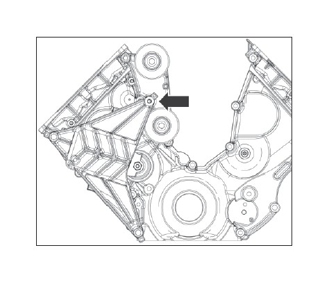
4. Install two (2) idler pulleys (953045) onto the machined posts of the upper FEAD bracket. Secure the pulleys using two (2) M8 x 1.25 x 28 mm idler bolts (R18020060-00) found in Hardware Kit C (1315-TVSHKC). Torque bolts to 25 Nm.
5. Loosely install the FEAD tensioner bracket assembly (13118B603) onto the front cover using two (2) M8 x 1.25 x 120 mm bolts (N811329-S437) found in Hardware Kit C (1315-TVSHKC), leaving at least a 10 mm gap between the two (2) new FEAD brackets.
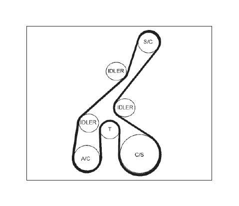
6. Route the FEAD belt (6K2085-8620). Do not route the belt onto the supercharger pulley.
7. Install one (1) M8 x 1.25 x 41 mm (W705128-S437) bolt found in Hardware Kit C (1315-TVSHKC), to fasten the tensioner bracket to the upper FEAD bracket. Torque all three (3) tensioner bracket bolts to 20-30 Nm.
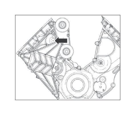
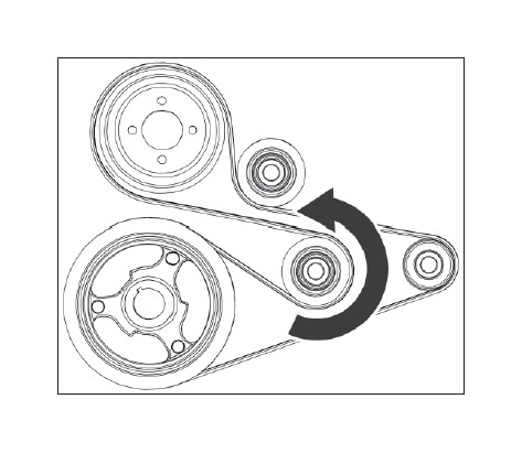
8. Using a 17 mm socket, rotate the new tensioner clockwise to install the belt on to the supercharger pulley. Inspect each pulley to ensure the belt is properly seated.
9. Re-install the coolant pump pulley using the four (4) take-off bolts. Torque bolts to 20-30 Nm.
10. Re-install the stock FEAD belt by rotating the tensioner counterclockwise and routing the belt as per the stock Ford belt routing.
11. Using a 1/4-inch drive extension as a feeler gauge, make sure it fi ts between the tensioner bracket and the air conditioning line.
INTERCOOLER RESERVOIR MOUNTING
1. Remove the bolt attaching the radiator overfl ow tank to the fan shroud at the left (driver) side. Set the bolt aside; this bolt location will be used for the degas bottle mounting bracket attachment.
2. Using the degas bottle-to-fan shroud mounting bracket (1115-6B634) as a template, mark and drill a new mounting hole in the fan shroud.
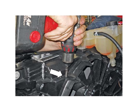
3. Install a M6 J-clip (N623332-S439) supplied in Hardware Kit E (1115-TVSHKE) over the drilled hole.
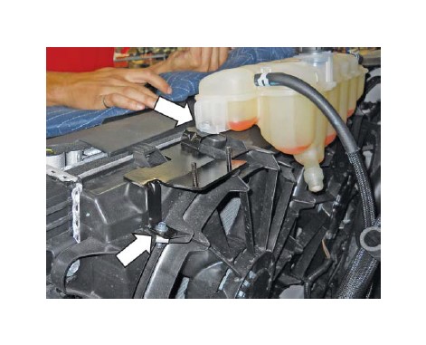
4. Place the mounting bracket (1115-6B634) in position on the fan shroud with the RH mounting hole under the overfl ow tank and the left hole over the new J-clip. Install the original overfl ow tank bolt in the RH mounting hole and an M6 x 1.0 x 20 bolt to secure the bracket in the lower LH J-clip. Torque to 10 Nm.
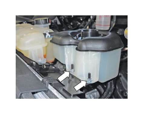
5. Install the degas bottle (R07070007) over the two (2) studs on the mounting bracket. Install two (2) M6 nuts (W520412-S437) found in Hardware Kit E (1115-TVSHKE), over the studs and torque to 10 Nm.
INTERCOOLER RADIATOR ASSEMBLYMOUNTING
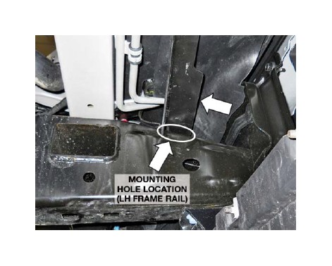
1. Install the LTR mounting spanner bracket (1115- 8K241) on the vehicle between the LH and RH frames rails as follows:
• Locate the open hole in the top of the LH frame near the front and the corresponding open hole in the RH frame rail.
• Insert an M8 x 1.25 J-clip (W520823-S439) supplied in Hardware Kit F (1115-TVSHKF) through the opening in each frame rail and over the mounting hole.
• Place the spanner bracket in position on top of the frame rails with the fl ange to the rear and facing down.
• With the mounting holes aligned, install two (2) M8 x 1.25 x 29 bolts (W500224-S437) to attach the spanner bracket to the frame rails. Torque to 25 Nm.
2. Remove the two (2) OEM bolts at the base of the bumper beam inboard of the LH and RH frame rails. These holes will be the attachment point for the lower LTR mounting brackets. The OEM bolts are not reused.
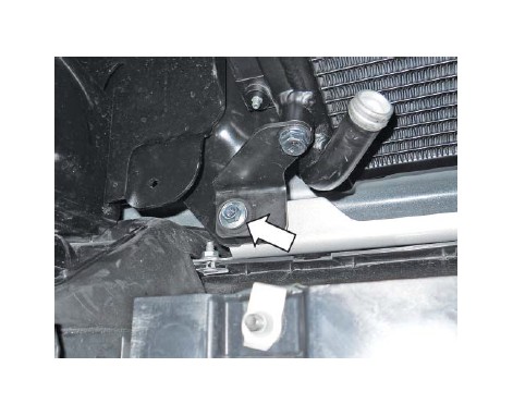
3. Place the LTR assembly (1115-8K229) in position between the spanner bracket at the top and the bumper beam. Install two (2) M8 x 1.25 x 20 bolts (90386A108) supplied in Hardware Kit F (1115-TVSHKF) to attach the LTR to the spanner bar. Torque the bolts to 25 Nm.
4. Align the lower LTR brackets with the open holes in the support panel and install the longer M8 x 1.25 x 33 bolts (N808920-S437) supplied in Hardware Kit F (1115-TVSHKF) to attach the LTR brackets to the bumper beam. Torque the bolts to 25 Nm.
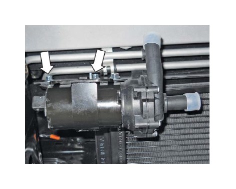
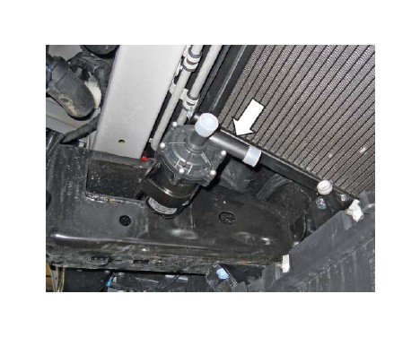
INTERCOOLER PUMP MOUNTING
1. Place the intercooler pump mounting bracket (R07070065-4G) in position on the intercooler pump (F8YH-8501) as shown and hand tighten the clamp bolt. Do not fully tighten the bolt at this time to allow for proper alignment of the inlet and outlet ports during installation in the vehicle.
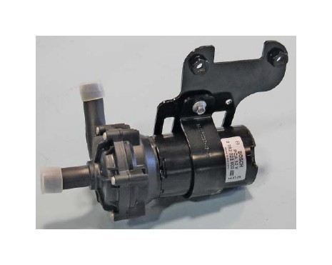
2. Install the pump and bracket assembly on the LTR spanner bracket using two (2) M8 x 1.25 x 29 bolts supplied with Hardware Kit F (W500224-S437). Position the pump so that the inlet tube is facing the LTR outlet tube. Torque the bolts to 25 Nm.
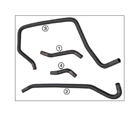
COOLANT HOSES
Intercooler Hose Circuit
Following are the four (4) 3/4" hoses that make up the intercooler circuit.
1. Intercooler reservoir inlet hose (1115-8D031)
2. Intercooler pump inlet hose (1115-1115-8D029)
3. LTR outlet hose (1115-8D030)
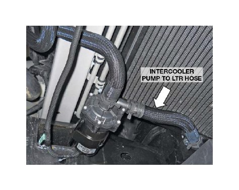
4. Intercooler pump-to-LTR hose (1115-8K236)
NOTE: Route all intercooler hoses very carefully. It is critical for intercooler performance that these hoses are not kinked once installed into the vehicle.
Starting at the top of the engine, install the hoses as follows.
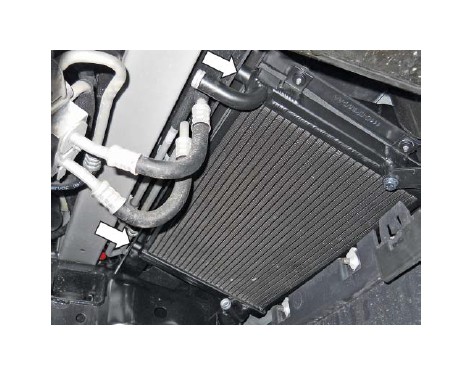
1. Route the LTR outlet hose (1111-8D030) from the intercooler down along the left radiator support and through the opening between the frame and radiator. Connect the hose to the lower port on the intercooler using one (1) 3/4" constant tension clamp (CT19x12-BO). This can be found in Hardware Kit D (1115-TVSHKD).
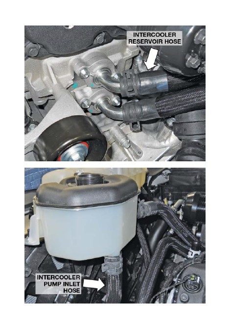
2. Route the intercooler pump inlet hose (1115- 8D029) from the degas bottle outlet port (bottom port) to the inlet port of the intercooler pump by routing the hose along the radiator support at the left front of the engine. Route the hose through the opening between the frame rail and the radiator support. Connect the hose to the degas bottle using one (1) 3/4" constant tension clamp (CT19x12-BO).
3. Install the intercooler reservoir hose (1111-8D031) between the intercooler outlet port and top port on the degas bottle (facing the cowl). Secure the hose to the inlet of the degas bottle using one (1) 3/4” constant tension clamp (CT19x12-BO).
4. Connect the intercooler pump inlet hose (1115- 8D029) from the degas bottle outlet port to the inlet port on the pump using one (1) 3/4" constant tension clamp (CT19x12-BO) at each end.
5. Install one (1) 3/4" constant tension clamp (CT19x12-BO) onto each end of the intercooler pump-to-LTR hose (1115-8K236). Install the hose onto the pump outlet and onto the LTR inlet; position the clamps to secure the hose.
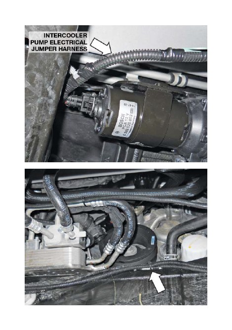
6. Connect the intercooler pump electrical jumper harness (1315-8W501) to the pump. Then, using a zip tie, secure the harness to the transmission cooler line at the center of the front crossmember.
7. On the passenger side of the LTR, connect the LTR outlet hose (1115-8D030) from the intercooler lower port to the outlet port on the LTR using one (1) 3/4" constant tension clamp (CT19x12-BO).
Heater Hose
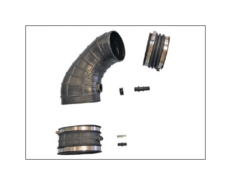
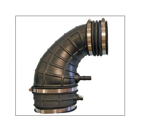
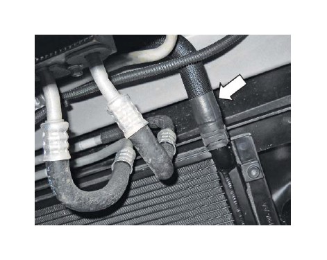
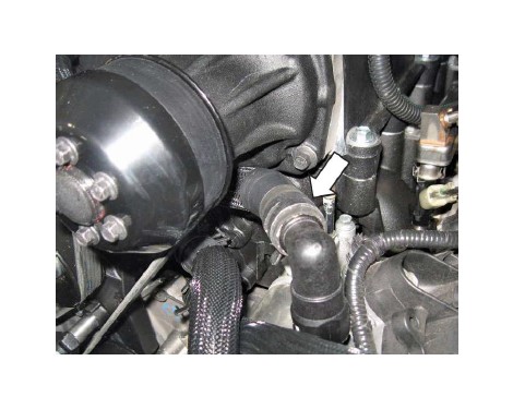
1. Route the new heater inlet hose assembly (1115- 18K579) underneath the drive snout of the supercharger and connect the 90-degree quickconnect fi tting to the heater return tube.
2. Remove the turret bolt on the upper passenger side of the engine, and install the P-clip that was in the heater hose kit. Wrap the clip around the heater inlet hose as shown and re-install the turret bolt. Torque to 10 Nm.
3. Connect the other end of the heater inlet hose assembly (1115-18K579) to the heater hose Tfi tting at the passenger side of the engine and secure with a clamp (8863T78). Route the two (2) heater hoses together and re-connect the plastic hose connector that will hold them together.
4. Reinstall the upper radiator hose and connect to both the engine and radiator.
5. Reinstall the factory 3/8" engine degas bottle hose between the new degas bottle and the fi tting on the driver side cylinder head. Secure with the constant tension clamp.
AIR INDUCTION SYSTEM
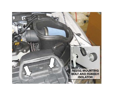
1. If not already done, reinstall the OEM mounting bolt and rubber isolator. Place the new ROUSH air box and OEM dirty air duct assembly in position on the vehicle. Align and slide the edge slot of the air box into the rubber isolator and secure the assembly in place with the two (2) original pushpins at the front of the dirty air duct.
2. Install the new clean air tube assembly (1115SC- 9B660) into position between the throttle body and the MAF tube. Torque the clamps on each end to 3 Nm.
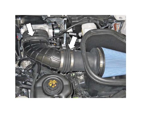
3. Connect the PCV fresh air inlet line from the cam cover and to the quick-connect fi tting on the clean air tube. Connect the bypass vacuum line to the small upper fi tting and the brake aspirator hose to the lower fi tting in the cuff at the throttle body.
FINAL ASSEMBLY
1. Cut a 25 cm piece of heater hose from the discarded piece. Carefully cut the piece open as shown.
2. Use the piece of hose to cover the PCV line on the passenger side coil cover. Use two (2) zip ties to attach it at each end.
3. Fill the engine cooling system (using a proper coolant mixture) to the marked level on the radiator degas bottle. Make sure the radiator petcock is closed tightly.
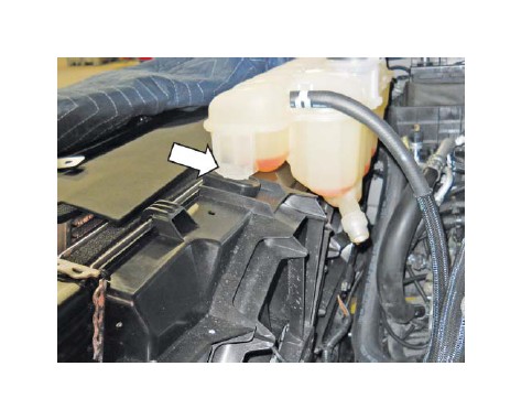
4. Using the same coolant mixture, fi ll the intercooler system through the degas bottle. The coolant should be approximately one inch below the top of the cap. Install the degas bottle cap (9C3Z- 8101) and tighten when full.
IMPORTANT: Both coolant systems can trap a large amount of air. It is very important to verify that the air is purged and that coolant is fl owing properly through both systems. ROUSH recommends vacuum fi lling both systems to properly evacuate the trapped air.
5. Inspect all underhood wiring harnesses for potential interference issues. Use zip ties to safely position the harness away from any areas of concern.
6. If the PCM was removed and shipped to ROUSH for a ROUSH-performed fl ash, reinstall it once the PCM is returned from ROUSH. If you are equipped with a SAE J2534 pass-through device, refer to the PCM Flashing section when installation is complete. DO NOT ATTEMPT TO REINSTALL THE PCM AND START THE VEHICLE IF THE PCM IS NOT EQUIPPED WITH A ROUSH CALIBRATION. OPERATING THE ENGINE WITHOUT THE RECALIBRATED PCM WILL RESULT IN ENGINE DAMAGE OR FAILURE AND WILL VOID THE WARRANTY.
7. Re-install the battery into the vehicle and make the terminal connections by connecting the positive ( ) cable fi rst then connecting the negative (-) cable.
8. Reconnect the fuel pump control module electrical connector located above the spare tire on the frame.
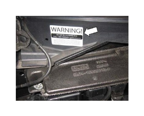
9. Place the PCM warning sticker above the PCM on the cowl of the vehicle.
10. The belt routing diagram (13116E072) is to be placed on the underside of the hood, on the driver side, opposite of the factory Vehicle Emission Control Information decal.
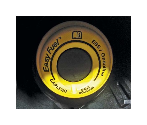
11. Place the fuel door decal (R0711005) on the backside of the fuel door. With the supercharger system installed, the vehicle is no longer E85 compatible. If your vehicle has a Flex-Fuel badge, it is recommended that this also be removed at this time.
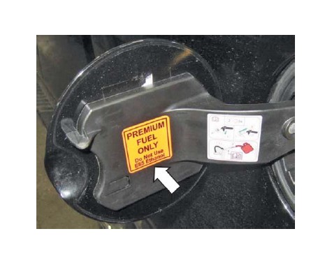
12. Place the premium unleaded fuel only decal (13109A095) inside the fuel door, below the fuel fi ller neck.
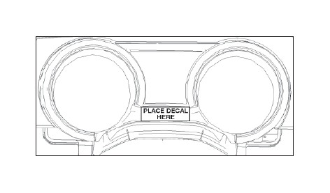
13. Place the "Premium Fuel" clear decal with white lettering on the instrument cluster bezel, on the fl at area below the small center gauges as shown.
14. If performing the PCM Flash procedure, proceed to the "PCM Flashing" section. If the PCM was sent to ROUSH for the Optional ROUSH Performed Flash and it has been reinstalled, start the engine and check for unusual noise, dash service lights, and/or unusual operation. If problems are detected, immediately stop the engine or vehicle, diagnose and repair the problem.
Congratulations, you can now go enjoy your new ROUSHcharged 5.0L F-150.
PCM FLASHING
1. If equipped with a SAE J2534 pass-through device, refer to the RDT-CALIM manual included in the CALKIT for PCM fl ashing. The RDT-CALIM manual will guide you through the ROUSH Diagnostic Tool (RDT) software installation process and the ROUSH PCM fl ashing procedure. OPERATING THE ENGINE WITHOUT THE RECALIBRATED PCM WILL RESULT IN ENGINE DAMAGE OR FAILURE AND WILL VOID THE WARRANTY.
2. Once the PCM has been successfully recalibrated, start the engine and check for unusual noises, dash service lights, and unusual operation. If problems are detected, immediately stop the engine or vehicle, diagnose and repair the problem.
SECTION E – UPPER AND LOWER GRILLE REMOVAL
REMOVAL PROCEDURE
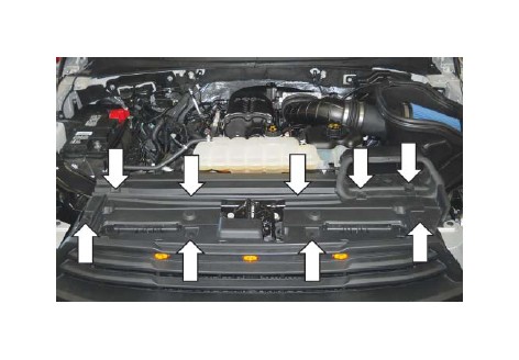
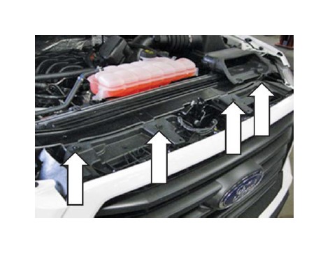
1. Remove the grille closeout by using a trim tool to take out ten (10) pushpins. Retain the close out and pushpins for reinstallation.
2. Remove the four (4) 10 mm screws that hold in the front grille. Retain the bolts for reinstallation.
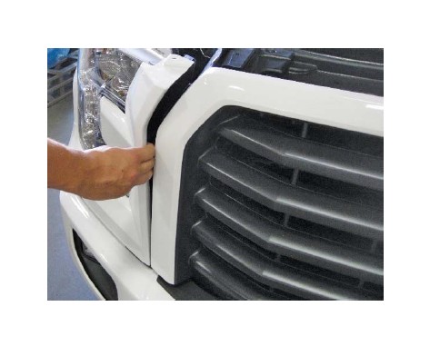
3. Remove the pushpins (2 total) on either end that hold the side grille pieces. Retain the pushpins for reinstallation.
4. Release the clips on the side grille pieces, but DO NOT COMPLETELY REMOVE THEM.
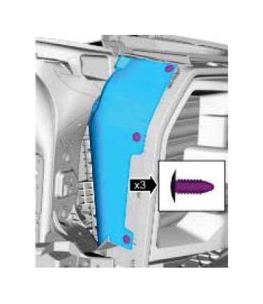
5. Use a trim tool to remove three (3) pushpins that attach the liner to the grille. Repeat this on the other side. Retain pushpins for reinstallation.
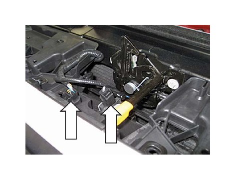
6. Unplug the wire harnesses on the top center of the grille.
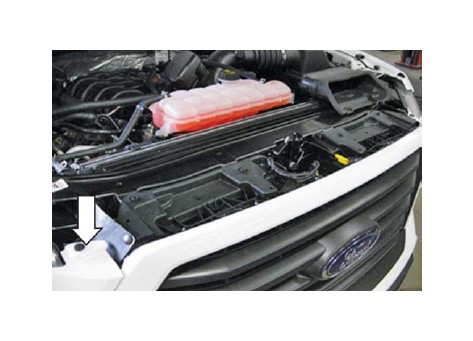
7. Remove the 8 mm screws at the bottom corners of the grille. Retain the two (2) fasteners for reinstallation.
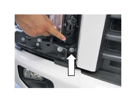
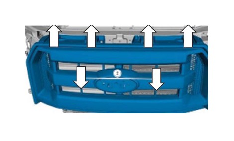
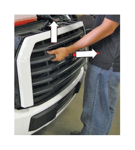
8. Remove the grille by pulling upward fi rst to disengage the locating pins on the top of the grille. Then pull forward on the center of the grille to remove it.
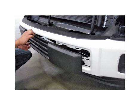
9. Unfasten the lower grille liner by removing the pushpins that are attached to the front bumper.
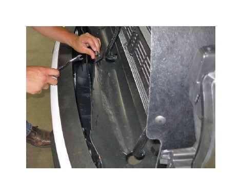
10. Remove the lower grille by unlatching the clips that hold it onto the bumper.
NOTE: Flat-jaw pliers can be used to compress the clips for easier removal.
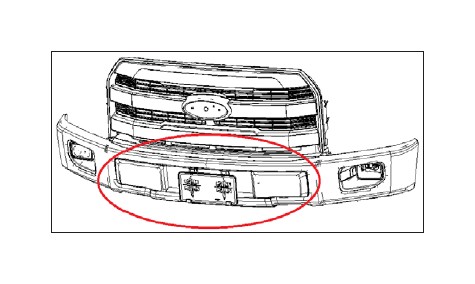
11. Modify the stock bumper cover to provide an opening for the radiator, purchase Ford EcoBoost part (FL3Z-17E810-DA) shown below and reverse the removal procedure or purchase Roush bumper cover.