FREE 1 to 3-Day Delivery on Orders $149+ Details
How to Install Rough Country Suspension Lift Kit on your F-150
Installation Time
1 days
Tools Required
- 5mm wrench /socket
- 8mm wrench /socket
- 10mm wrench /socket
- 11mm wrench /socket
- 12mm 12 point wrench
- 14mm wrench /socket
- 15mm wrench /socket
- 16mm wrench /socket
- 18mm wrench /socket
- 19mm wrench /socket
- 21mm wrench /socket
- 22mm wrench /socket
- 24mm wrench /socket
- 30mm wrench /socket
- Floor Jack
- Jack stands
- Hammer
- 7/16” wrench /socket
- 9/16 wrench /socket
- 5/8” wrench /socket
- 3/4” wrench /socket
- 1 1/16 socket
- Drill
- 17/32” Drill Bit

Shop Parts in this Guide
THANK YOU FOR CHOOSING ROUGH COUNTRY FOR YOUR SUSPENSION NEEDS.
Rough Country recommends a certified technician install this system. In addition to these instructions, professional
knowledge of disassemble/reassembly procedures as well as post installation checks must be known. Attempts to install
this system without this knowledge and expertise may jeopardize the integrity and/or operating safety of the vehicle.
Please read instructions before beginning installation. Check the kit hardware against the parts list on the next 2 pages.
Be sure you have all needed parts and know where they go. Also please review tools needed list and make sure you
have needed tools.
INSTALLATION INSTRUCTIONS
1. Chock the rear wheels and jack up the front of the vehicle.
2. Place jack stands under the frame rails and lower onto jack stands.
3. Remove the wheels/tires.
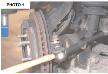
4. Remove tie-rod end using a 21mm wrench. Using a hammer hit the side of the knuckle to pop tie-rod out. Photo 1.
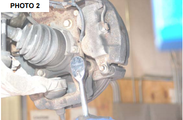
5. Using a 18mm socket remove brake caliper as shown in Photo 2. Hang caliper out of way. Do not let caliper hang
by brake hose as this will damage hose. Remove rotor.
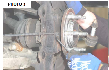
6. Using a 5mm Allen-wrench remove ABS wire from wheel bearing and remove vacuum hoses from knuckle. Retain
factory hardware. See Photo 3.
7. Remove the dust cap from the knuckle and remove the 13mm axle nut.
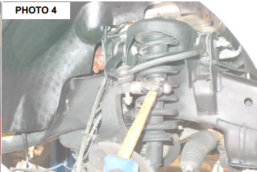
8. Remove the upper ball joint nut on the knuckle using a 21mm wrench. Use a hammer as shown in Photo 4 to separate
the ball joint from the knuckle.
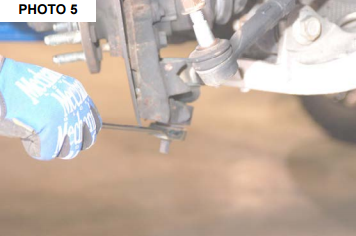
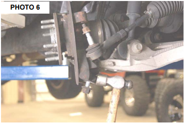
9. Remove the lower ball joint nut from the knuckle using a 24mm wrench. See Photo 5. Use a hammer as shown in
Photo 6.
10. Remove the knuckle from the vehicle. Be sure not to overextend or pull out the CV axle shaft.
11. Repeat steps 4-10 for opposite side of the vehicle.
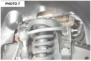
12. Remove the upper strut mounting nuts as shown in Photo 7 using a 15mm wrench and retain the nuts for reuse.
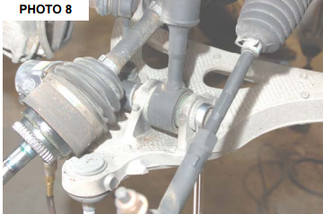
13. Remove the lower strut mount bolt from the lower control arm using a 30mm socket and 1 1/16” wrench as shown in
Photo 8 and remove the strut from the vehicle.
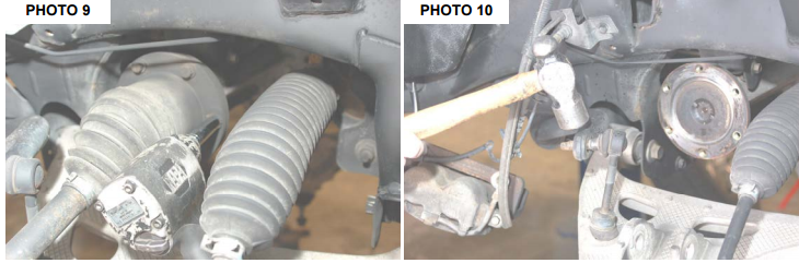
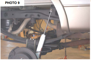
14. Remove the axle shaft bolts using a 12mm 12point socket as shown in Photo 9 and remove the axle shaft. Retain
the hardware for reuse.
15. Remove the nut from the sway bar link using a 21mm wrench and retain the factory nut. It may be necessary to use
a hammer as shown in Photo 10 to separate the sway bar link from the sway bar.
16. Remove the bolts on the lower control arm using a 21mm and a 1 1/16” wrench and remove the lower control arm.
17. Repeat steps 12-16 for the opposite side.
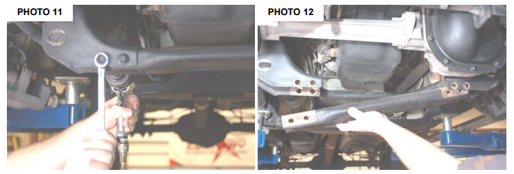
18. Remove the center cross-member bolts as shown in Photo 11 using a 18mm and a 13mm wrench. Remove the
cross-member as shown in Photo 12.
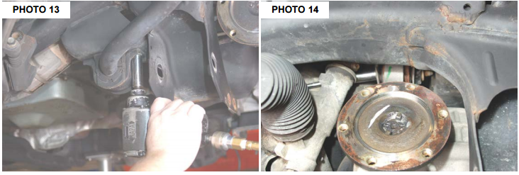
19. Remove the sway bar as shown in Photo 13 using a 15mm socket. Set sway bar aside and retain hardware for reuse.
20. Remove the drive shaft bolts using a 12mm 12point socket. Secure driveshaft out of harms way.
21. On the driver side. Remove the upper differential bolt as shown in Photo 14 using a 15mm socket. Retain for reuse.
It may be necessary to slightly turn the steering wheel to allow the bolt to clear the steering assembly.
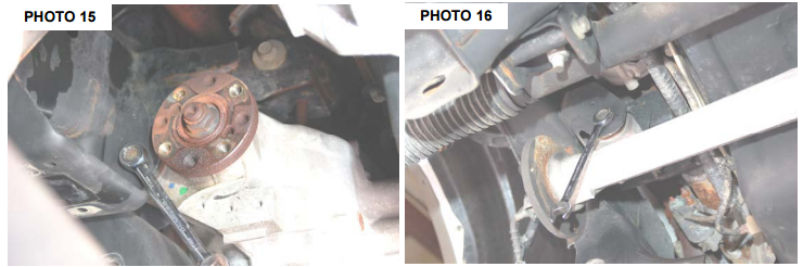
22. Loosen the rear driver side bolt and the passenger side bolt on the differential using a 15mm wrench. Photo 15 and
16.
23. Place a floor jack under the front differential and remove both bolts and set differential aside.
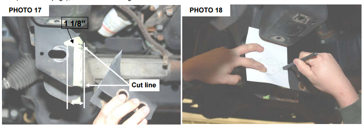
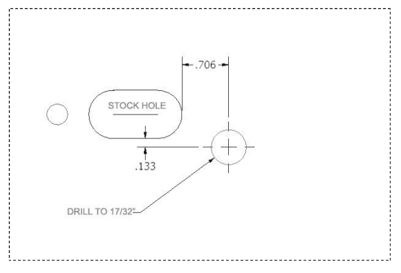
24. On driver side stock frame; measure over 1 1/8” from hole as shown and 3 1/2” from the bottom up. See Photo 17.
Mark the area and cut using a reciprocating saw. Paint cut area to prevent rusting. Using supplied drilling template
(next to last page), mark and drill using a 17/32” bit. See Photo 18.
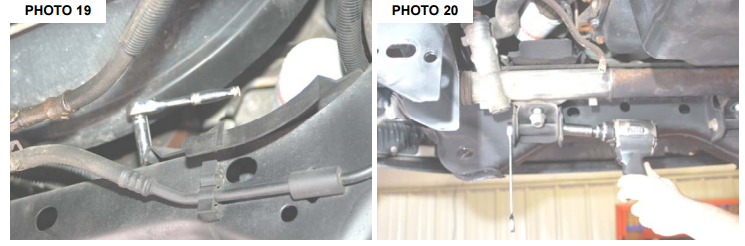
25. Remove the oil catch pan using 10mm wrench. See Photo 19.
26. Remove the nuts on the rack and pinion mounting bolts using a 24mm socket. Also remove the bolts from the rack
and pinion mounting plates using 18mm wrench. Use a jack stand to support the rack and pinion do not let the rack
hang or you may damage it or the hoses. See Photo 20.
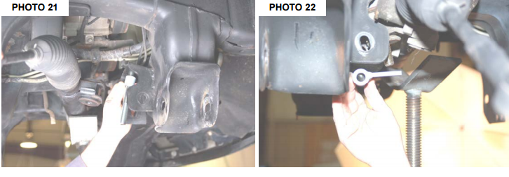
27. Replace rack and pinion bolts with the new 16mm x 130mm long bolts and install the 1” spacer above the rack and
pinion to space the rack down. See Photo 21.
28. Install new rack and pinion mounting plates with factory hardware do not tighten at this time. Mount the plate with the
hole offset down as shown in Photo 22.
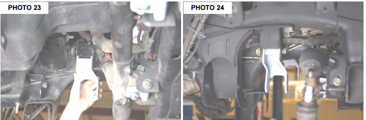
29. Install driver side differential bracket with factory hardware as shown in Photo 23 with the offset to the front of the
vehicle. .Do not tighten at this time.
30. Install passenger side differential bracket with factory hardware as shown in Photo 24 with the offset to the front. .
Do not tighten at this time.
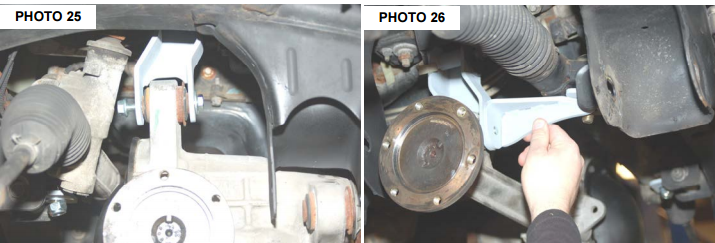
31. Raise the differential into position with a floor jack and install using the new 12mm x 100mm bolt on the passenger
side. Do not install nut at this time. On the driver side make sure differential clears the rear lower control arm pocket
that was cut. Trim if necessary and install the supplied 12mm x 90mm bolts back to front. See Photo 25.
32. Install passenger side support bracket to rack and pinion bolt to passenger side differential bolt. See Photo 26.
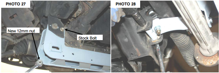
33. Install rear cross-member using factory bolts and install differential bolt with new 12mm nut shown in Photo 27. It
may ease installation to tape the nut to the wrench to install on bolt.
34. At this time tighten rack and pinion bolts using a 24mm wrench. Then tighten the rack and pinion mounting plates
using 18mm wrench and tighten the upper differential bolts using a 15mm wrench and tighten the lower differential
bolts using a 18mm and 19mm wrench. See Photo 28.
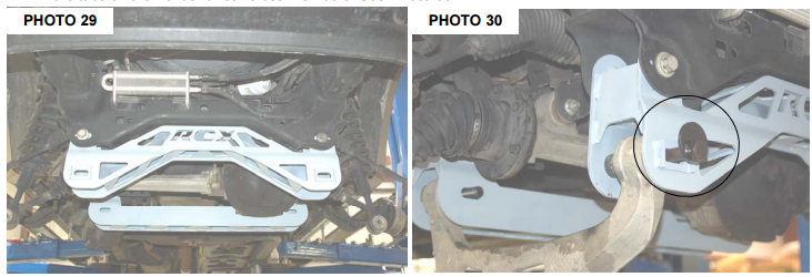
35. Install front cross-member using factory hardware. See Photo 29. Do not tighten at this time.
36. Install lower control arms using the supplied 18mm x 150mm cam bolts, washers and nuts so the offset washer rests
in the tabs on the front and rear cross-members. See Photo 30.
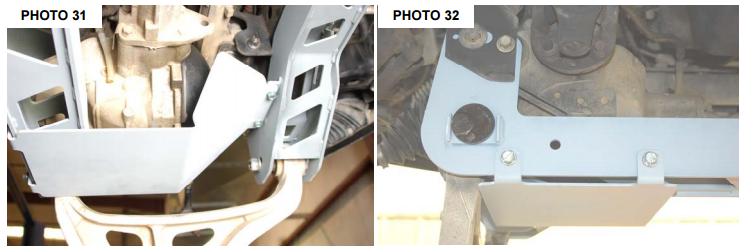
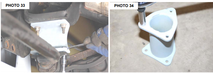
37. Install new skid plate using the 3/8 self tapping bolts on front cross member and on the rear cross member using a
9/16” mm wrench as shown in Photo 31 & 32.
38. At this time tighten all cross-member bolts using a 21mm and a 1” 1/16 wrench and the rear differential bolt using a
15 mm wrench. Tighten the lower control arm bolts to 200 ft/lbs.
39. Install the new sway-bar drop brackets on the frame using factory hardware and a 15mm wrench.
40. Reinstall front driveshaft using 12mm 12 point socket.
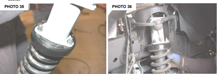
41. Install the sway bar onto the new bracket using the 3/8 x 1” bolts as shown in Photo 33. Tighten using a 9/16” wrench.
42. Reinstall sway-bar link back into sway-bar. Using a 21mm wrench tighten nut.
44. Install the supplied 10mm studs in the strut spacer as shown in Photo 34. Using a 17mm socket to tighten.
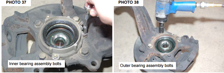
45. Install the strut spacer on the strut as shown in Photo 35 with factory hardware. Install the strut in the upper mount on
the vehicle as shown in Photo 36 with the supplied 10mm flat washers, lock washers and nuts using a 17mm wrench.
Install the lower strut mount in the lower control arm with factory hardware and using a 30mm socket and a 1” 1/16
socket.
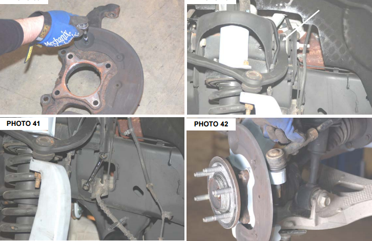
46. Remove the inner bearing assembly using 8mm wrench and remove the outer bearing assembly using a 15 mm
wrench. See Photo 37 & 38. Remove the dust shield using a 8mm wrench as shown in Photo 39 and install to new
knuckle. Install bearing assembly into new knuckle. Install the new Rough Country knuckle in the stock location with
factory hardware. Using a 21mm wrench tighten the upper ball joint and a 24mm wrench tighten the lower ball joint.
47. Slide the CV axle shaft in the knuckle and tighten with stock nut and using a 13mm wrench. Reinstall the CV shafts
on the differential with the factory hardware and using a 12mm 12 point socket. Install the outer dust cap.
48. Install ABS wire back into bearing using a 5mm allen wrench then install rotor and brake caliper with factory hardware
using a 18mm wrench to tighten bolts . Reroute line as shown in Photo 40 and install vacuum hose. Using a
10mm wrench remove the brake line bracket from the frame as shown in Photo 41. Replace the front brake lines
with the new supplied brake lines/crush washers using 14mm,16mm and a 11mm wrench. Bleed the brakes and
check brake fluid level. Reinstall brake line brackets with the factory hardware in the stock location.
49. Flip the tie-rod end and install into the knuckle using a 21mm wrench to tighten. See Photo 42.
50. If optional kicker bars were purchased with this kit, install at this time per the instructions included with that kit.
51. Install tires and wheels and lower to the ground. Tighten the lower control arm bolts.
REAR INSTALLATION
1. Chock the front tires and jack the rear the rear end up. Put jack stand under the frame rail and lower truck onto jack
stands.
2. Remove tires and wheels.
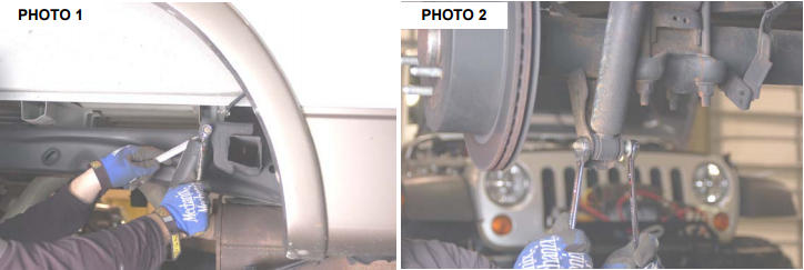
3. Remove rear shocks from the upper and lower mount using 18mm and a 15mm wrench. See Photo 1 & 2.
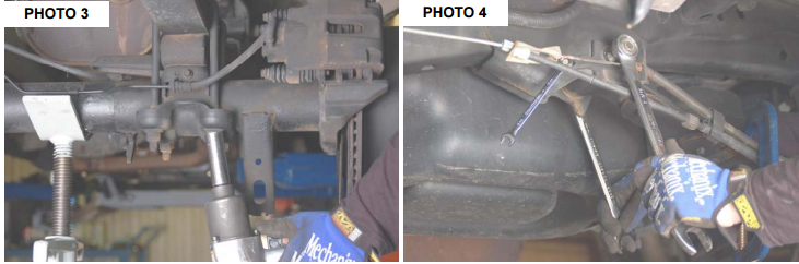
4. Using a jack support the rear end on one side and remove U-bolts using a 21mm socket. Remove the factory block.
See Photo 3.
5. Remove the e-brake cable from the factory e-brake bracket.
6. Remove the stock driver side emergency brake cable bracket if so equipped using 10mm wrench,1” 1/16 and a
15/16 wrench. See Photo 4. Disconnect the e-brake cable from the main cable and discard stock bracket if so
equipped.
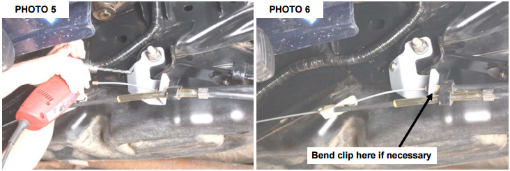
7. On some models it will be necessary to mark and drill the holes. If needed drill using a 11/32” bit as shown. See
Photo 5.
8. Reinstall the e-brake cable into the new brackets using factory hardware and 5/16x 1 bolt, washer &nut. Tighten factory
bolts and new bolts using 24mm and 13mm wrench and reconnect the e-brake cable as shown. It may be necessary
to slightly bend the clip on the e-brake cable to ensure the cable remains on the bracket. See Photo 6.
9. Install new block as shown in Photo 7. Raise axle using the jack until axle pins line up with hole and pin in block.
10. Secure block to axle and spring installing the 9/16 x 3” square U-bolts as shown. Tighten nuts to factory torque using
a 7/8” socket.
11. Install 7/16 x 3 square u-bolts as shown and tighten nuts
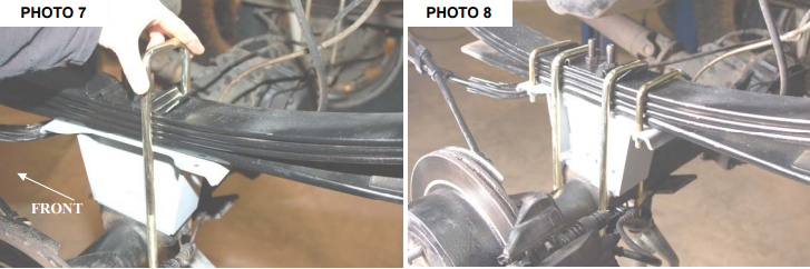
using a 5/8” socket. See Photo 8.
12. Install the bushing and sleeves into the shocks and install on the truck with factory hardware. Tighten using 15mm
and a 18mm wrench.
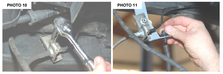
13. Remove the stock rear brake line bracket from the frame using a 10mm wrench. See Photo 10. Install the new
brake line bracket on the drivers side frame rail in the stock mount with factory hardware and install the stock brake
line bracket to the new bracket with the supplied 5/16” x 3/4” bolt/washers & nut. Remove the stock diff hose from
the stock mount and install into the new bracket. See Photo 11.
14. Install the wheels and tires.
15. Jack up the vehicle and remove the jack stands. Lower the vehicle to the ground with floor jack.
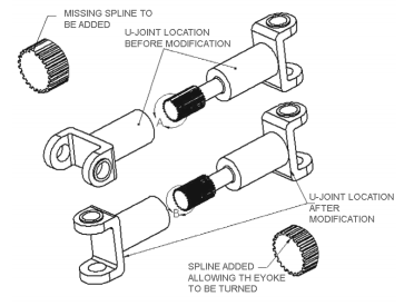
FRONT DRIVESHAFT RECLOCKING INSTRUCTIONS
Driveshaft modification will need to be performed if the vehicle experiences a driveshaft vibration . The reason for this
vibration is that the factory driveshaft u-joints are not aligned from the factory. The next steps will allow the yoke to be
turned on the driveshaft, thus eliminating the factory vibration. Normally this vibration is only felt when the vehicle is in
4wd at speeds in excess of 40mph.
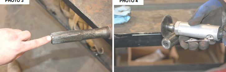
1. Mark the driveshaft as shown in Photo 1. and Unclamp the boot on the driveshaft as shown in Photo 2.
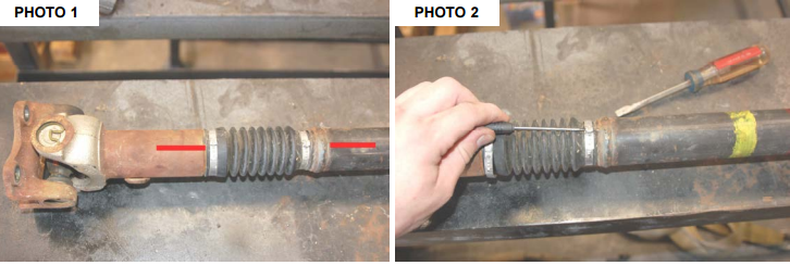
2. Remove the stock clamps and driveshaft boot and separate the driveshaft. Locate the tab on the driveshaft splines
to be ground. See Photo 3.
3. Groove the shaft as shown with die grinder as shown in Photo 4.
4. The finished groove is shown and will be the same as the rest of the grooves.
5. Reinstall the driveshaft yoke 90 degrees from where it was factory. This will align the u-joints. Make sure the u-joints
are aligned before assembling the shaft.
6. Re-clamp the boot on the driveshaft with the factory clamps and using a clamping tool.
POST INSTALLATION INSTRUCTIONS
1. Check all fasteners for proper torque. Check to ensure there is adequate clearance between all rotating, mobile,
fixed and heated members. Check steering gear for interference and proper working order. Test brake system
2. Perform steering sweep. Check to ensure brake hoses have sufficient slack and will not contact rotating, mobile, or
fixed members, adjust lines/brackets to eliminate interference and maintain proper working order. Failure to perform
inspections may result in component failure
3. Readjust headlights to factory settings
4. Have vehicle aligned by a certified alignment professional.
5. Re-torque all nuts, bolts, and especially u-bolts after the first 100 miles, again after another 100 miles and then check
periodically thereafter
6. All components must be retightened after 500 miles, and every three thousand miles after installation.
7. Rough Country recommends not operating the vehicle in 4 wheel drive above 40 mph. Doing so may result in a low
frequency front driveshaft vibration. If vibration does occur please refer to included instructions in this sheet to reclock
the driveshaft.