 FREE 1 to 3-Day Delivery on Orders $149+ Details
How to Install a Rough Country 5 in. Suspension Lift Kit on your Ford F-150
Installation Time
1 days
Tools Required
- 8mm socket
- 12mm socket
- 14mm socket
- 18mm socket
- 22mm socket
- 36mm socket
- 10mm wrench
- 12mm wrench
- 15mm wrench
- 21mm wrench
- 24mm wrench
- Torsion Bar Tool
- 5/64 drill bit
- Drill
- Jack stands (2)
- Safety Glasses and Gloves
- 10mm socket
- 13mm socket
- 15mm socket
- 21mm socket
- 24mm socket
- 8mm wrench
- 13mm wrench
- 18mm wrench
- 22mm wrench
- Torque Ratchet
- 17/64 drill bit
- Sawsall
- Grinder
- Floor jack

Shop Parts in this Guide
Thank you for choosing Rough Country for your suspension needs.
Rough Country recommends a certified technician install this system. In addition to these instructions, professional knowledge of disassemble/reassembly procedures as well as post installation checks must be known. Attempts to install this system without this knowledge and expertise may jeopardize the integrity and/or operating safety of the vehicle.
Please read instructions before beginning installation. Check the kit hardware against the kit contents list. Be sure you have all needed parts and know where they go, separating parts according to where they go and placing hardware with
the brackets before you begin with save on installation time. If you are missing any components, are unsure where they go, or have a question about the installation please call Rough Country at 800-222-7023.
PRE-INSTALLATION
Prior to beginning installation, carefully inspect the vehicle’s steering and driveline system paying close attention to the tie rod ends, ball joints, and wheel bearings. Additionally, check steering to frame and suspension to frame attaching
points for stress cracks. The overall vehicle must be in excellent working condition before beginning installation. Repair or replace all worn or damaged parts.
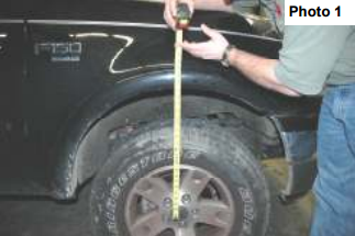
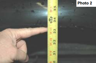
FRONT INSTALLATION
1. With the truck sitting on a level surface measure the distance from the center of the wheel to the bottom of the
fender. Record these Measurements. See Photo 1 & 2.
Front Driver ______ Front Passenger ______
Rear Driver ______ Rear Passenger ______
2. With the truck parked on a clean, dry, and level surface set the parking brake. Chock the rear wheels. Using a floor
jack raise the front of the truck and support the frame rail
with approved jack stands. NEVER WORK UNDER AN
UNSUPPORTED VEHICLE.
3. Using a 22 mm socket remove the lug nuts on the front
wheels and remove the front wheels
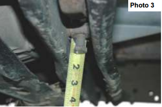
4. Measure the amount of thread showing on the torsion bar
adjuster bolts. See Photo 3. Drivers Side ______
Passenger Side ______ Using a 18mm socket remove the
adjuster bolt.
5. Using a Ford approved torsion bar tool, remove the torsion
bar adjuster nuts and adjusters. Set aside, these will
be reused.
6. Using a 18 mm wrench and 18 mm socket remove the
upper shock nuts. Using a 13 mm wrench and 18 mm
socket remove the lower shock bolt. Retain the lower
hardware for reuse.
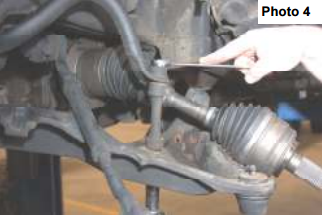
7. Using a 16 mm wrench and 15 mm socket remove the
stock sway bar links. See Photo 4.
8. Using a 13 mm wrench remove the brake caliper. Tie the
caliper up and out of the way. Do not let the caliper hang
from the brake line. Using a 18 mm socket remove the
brake caliper bracket.
9. Using a 8 mm socket remove the brake dust cover. This
will be reinstalled on the new knuckle.
10. Using a 8 mm socket remove the ABS hold down from the
knuckle. Using a 3/16 allen wrench remove bolt and
the sensor. Route this up to the frame rail. The allen bolt
will be reused.
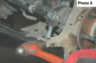
11. Using side cutters remove the cotter pin from the tie rod castle nut. Using a 21 mm socket remove the nut from the
tie rod. Using a hammer tap the knuckle as shown until the tie rod pops out. See Photo 5. Never hit the tie rod
itself.
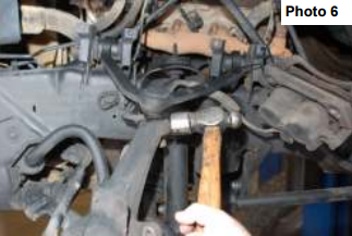
12. Using side cutters remove the cotter key from upper ball joint. Using a 21 mm socket loosen the nut. Hit the knuckle
as shown until the ball joint pops loose. See Photo 6.
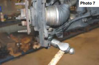
13. Using side cutters remove the cotter pin from the lower ball joint. Using a 24 mm socket remove the castle nut from
the ball joint. Using a hammer hit the knuckle as shown in Photo 7 until the ball joint pops free.
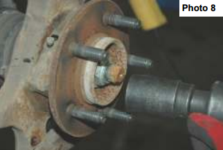
14. Using side cutters remove the cotter pin from CV shaft. Using a 36 mm socket remove the nut. See Photo 8.
15. Remove the nut from the upper ball joint and remove the knuckle from the truck. Using a 15 mm socket remove the
wheel bearing from the knuckle. Using a blunt punch and hammer remove the rear seal from the knuckle. Retain
hardware for reuse.
16. Using a 15 mm socket remove the six bolts that attaches each CV shaft to the front differential. Retain the bolts, they will be reused.
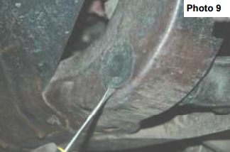
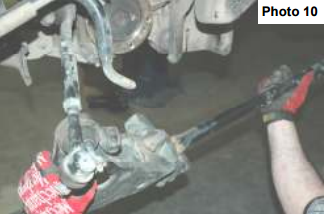
17 Using a flat head screw driver remove the plastic cover on the front frame rail. See Photo 9. Using a 21 mm socket and 24 mm wrench remove the front and rear lower control arm bolts. Be careful the torsion bar will come out with the control arm. See Photo 10. Remove the torsion bar. Scribe a mark on the torsion bar to note it indexing in relationship to the control arm. The bars are to be reinstalled in same relationship as removed.
18 Position a floor jack or jack stand under the differential
to allow the differential bolts to be removed.
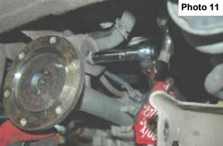
19 Using a 15 mm socket and 18 mm wrench remove the
passenger side upper bolt as shown in Photo 11 that
secures the differential to the frame. Retain the stock
hardware for reuse.
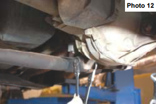
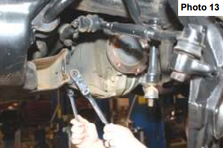
20. Using a 15mm socket and 18mm wrench remove the
driver side upper and lower differential bolts that secure
the differential to the frame. See Photo 12 & 13.
Retain the stock hardware for reuse.
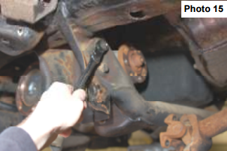
21. Using a 15 mm socket remove the bolts securing the rear
cross-member to the frame as shown in Photo 15 and
remove from the vehicle.
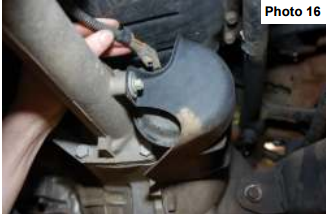
22. Unplug the Differential vacuum hoses. See Photo 16. Gently
pull down on the hoses giving it 5 inches of slack. Using
a 12 point 12 mm socket remove the four bolts that secure
the drive shaft to the differential. Retain hardware for reuse.
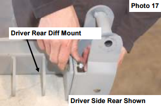
23. Locate the 4 cross member drop brackets and assemble
them using the 7/16” x 1 1/4” bolts, thick washers, and nylock
nuts with the cross members as shown in Photo 17.
Only three bolts per side will be used. Do not tighten
at this time.
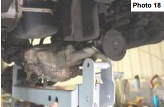
24. With the differential still supported with jack stands or a
floor jack and using the 9/16 x 5 1/5 bolts, install the crossmembers
into the lower control arm sockets as shown in
Photo 18. The bolts will be installed from the front to the
rear. Do not tighten at this time.
25. Assemble the front cross member the same as the rear with the supplied 7/16” x 1 1/4” bolts, washers/nuts. Only
three bolts per side will be used. DO not tighten at this time.
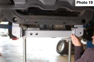
26. Install in the front factory location as shown in Photo 19 with the supplied 9/16” x 5 1/2” bolts. Do not tighten at this
time.
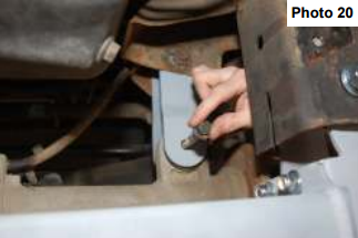
27. Install the diff drop bracket on the passenger side as shown in Photo 20 with the factory hardware on the frame and
the supplied 12mm x 100m bolts, washers /nuts on the differential. Do not tighten at this time.
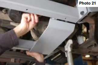
28. Install the skid plate on the drivers side as shown in Photo 21 on the differential tabs with the supplied 12mm x
100mm bolts, washers/nuts. Do not tighten at this time.
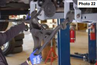
29. Remove the torsion bars from the lower control arms and install the lower control arms into the new brackets. With
the factory hardware. Slightly tighten the bolts. See Photo 22.
30. Tighten the 12 cross member bracket bolts to 45 ft lbs. Tighten the upper cross member bolts to 65 ft lbs.
31. Lightly pull the vacuum hose down and reinstall on the differential.
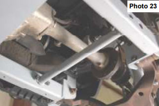
32. Locate the supplied spreader bars and install as shown in Photo 23 using the supplied 4-3/8” x 1” bolts/washers &
nuts. Tighten with a 9/16 wrench.
33. Using a 12 mm 12 point socket install the drive shaft with factory bolts.
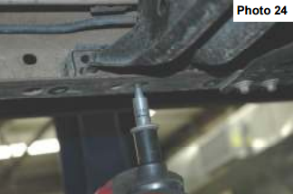
34. Using a 15 mm socket and a 18 mm wrench remove the front and rear bolts from the Torsion bar adjuster bracket.
Using a 18 mm socket and 18 mm wrench remove the center bolt. See Photo 24. Retain the two factory outer
bolts for reuse.
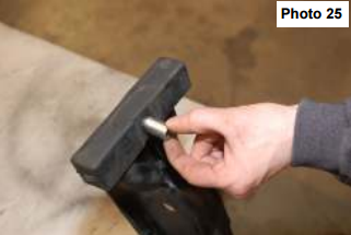
35. Install the supplied 12mm x 1 1/4” crush sleeve as shown in Photo 25 on the stock torsion bar cross member.
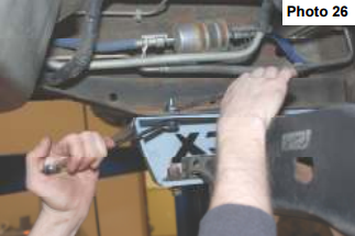
36. Locate the torsion bar drop brackets and install as shown using the supplied 7/16” x 1 1/4”bolts/washers & nuts. See Photo 26. Do not tighten at this time.
37. Install the factory cross member in the drop brackets as
shown with the factory hardware on the two outer bolts
and using the 10mm x 65mm bolt / washer & nuts in the
center. Do not tighten at this time. Slide the torsion bars
into the lower control arms.
38. Raise the torsion bar adjuster bracket into position in
the torsion bar cross member and install using factory
hardware.
39. Make sure that both sides of the drop bracket / torsion
bar cross member assembly are straight with the frame
tighten all hardware to 45 ft lbs.
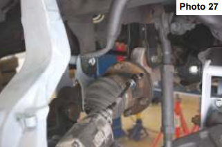
40. Using the factory CV bolts reinstall the CV shafts on the
differential as shown in Photo 27 using a 12mm 12
point socket.
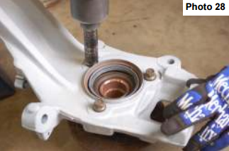
41. Locate the bearing assembly removed from the stock
knuckle. If the seal is in good condition, install the seal in the new knuckle. If necessary purchase new seals.
Install the bearing into the new knuckle with the factory hardware using a 15mm wrench. See Photo 28.
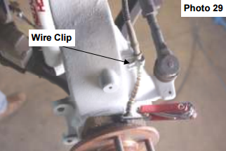
42. Reinstall the ABS sensors & wire clip as shown in Photo 29 using a 3/16” allen head wrench and install wire clip
onto new knuckle using a 8mm wrench.
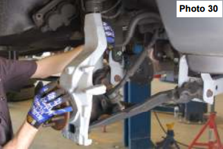
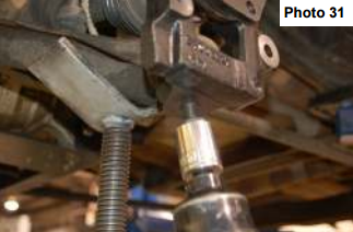
43. Install on the lower and upper ball joints as shown in
Photo 30 & 31 with stock hardware and supplied cotter
pin. Tighten using a 21mm wrench for the upper ball joint
and a 24mm on the lower ball joint.
44. Install the stock tie rod on the new knuckle with stock
hardware using a 21mm wrench. Install supplied cotter
pin.
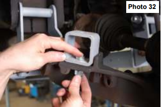
45. Install the bump stop extension bracket as shown in
Photo 32 using the supplied 1/2” x 1 1/2” bolts/washers &
nuts. Install the factory bump stop on top of the bracket
using factory hardware.
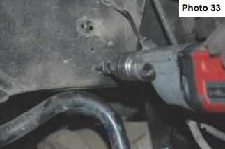
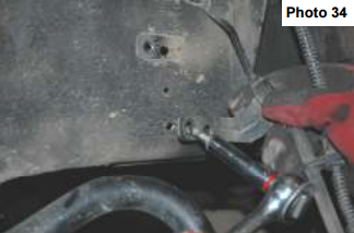
46. Using a 10 mm socket remove the brake line bracket from the frame rail. Measure down 2.5 inches and drill a hole
using a 17/64” bit. Using the factory screw reinstall the hold down in the frame. See Photo 33 & 34.
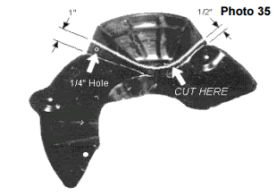
47. Trim the dust shield as shown and reinstall on the knuckle using it as a template to locate the 1/4” hole to be drilled.
Mark the hole, drill the 1/4’ hole and install on the knuckle. See Photo 35.
48. Using a 18 mm socket install the caliper hold down bracket.
49. Using a 13 mm wrench install the brake caliper.
50. Using a 36 mm socket install the outer CV shaft nut and torque to 85 ft lbs. Install the supplied cotter key.
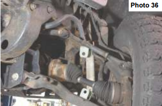
51. Install the new sway bar link bracket on the lower control arm as shown in Photo 36 with the supplied 12mm x
35mm bolts, flat washer and flange lock nut. Do not Tighten at this time.
52. Install the sway bar link bracket on the sway bar as shown in Photo 36 with the supplied 12mm x 35mm bolts, flat
washer and flange lock nut. Do not tighten at this time.
53. Install the sway bar link in the upper and lower bracket with the supplied 12mm x 65mm bolts with the head of the
bolts toward the rear of the vehicle.
54. Tighten all sway bar hardware using a 18mm & 19mm socket & wrench.
55. Install the front shock part number 650346 in the factory location with the factory hardware on the bottom of the
shock. Tighten with a 9/16” wrench on the upper and a 13mm & 18mm wrench for the lower.
56. Using the Ford approved torsion bar tool install the torsion bar adjusters and adjuster nuts. Using a 18 mm socket
set the torsion bars to factory setting.
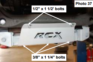
57. Install the supplied skid plate using the supplied 3-3/8” x
1 1/4” & 21/2” x 1 1/2” self tapping bolts. See Photo 37.
58. Tighten all hardware on the cross members, upper control
arms, and diff drop brackets. Do not tighten the
lower control arms until the vehicle is on the ground
and at ride height..
59. Install the wheels and tires and torque to factory.
60. Lower vehicle to the ground, set the ride height and
tighten the lower control arms.
REAR INSTALLATION
1. Raise the rear of the vehicle and support with approved jack stands. Remove the rear wheels.
2. Using a 18 mm socket and 18 mm wrench remove the lower shock bolt. Using a 18 mm wrench remove the upper
shock nut. Retain stock hardware.
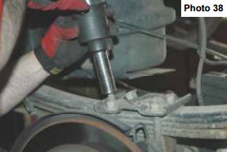
4. Using a 21 mm socket remove the u-bolts. See Photo 38. Doing one side at a time.
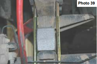
5. Install the new blocks under the factory block and new u-bolts and tighten to 85 ft lbs. See Photo 39.
6. Install new shocks part number 650333 with new nut for the top and factory bolt and nut on the lower.
7. Install the wheels and tires tighten to factory specs and lower vehicle on the ground.
OPTIONAL EQUIPMENT
OPTIONAL STEERING STABILIZER:
PART # 87343
Please contact your local Rough Country Dealer for more information.
POST INSTALLATION INSTRUCTIONS
1. Lug nuts should be check after 50 miles and all nuts and bolts should be checked and tightened after 500 miles. All
parts should be checked every 3000 miles for the life of the vehicle.
2. Recheck brake hoses and lines for proper clearances.
3. Perform steering sweep to check for appropriate tire clearance. Note- Some oversized tires may require trimming of
the bumper and valance
4. If new tires are installed that are more than 10% taller than original tires, the speedometer must be recalibrated for
the anti-lock brake system (if applicable) to function properly. Contact an authorized Ford dealer for details on recalibration.
5. Adjust headlights back to proper settings.
6. Have a qualified alignment center realign front end to factory specs.
7. Install “Warning to Driver” decal on sun visor.

