 FREE 1 to 3-Day Delivery on Orders $149+ Details
How to Install Rough Country 2.5 in. Leveling Lift Kit w/ Shocks on your F-150
Installation Time
3 hours
Tools Required
- 15mm Wrench
- 15mm Socket
- 1 1/16” Wrench
- 21mm Wrench
- 16 mm Wrench
- 21 mm Wrench
- 3/8” mm Wrench
- 9/16” Wrench
- 9/16” Socket
- Hammer
- Floor Jack
- Jack Stands
- 18mm Socket
- Air Chisel
- Round Nose Punch
- 2-Front Strut Extensions
- 1-Kit Bag that includes
- 6-3/8x2” Bolts
- 6-3/8” Flange Lock Nuts

Shop Parts in this Guide
Thank you for choosing Rough Country for all your suspension needs.
Rough Country recommends a certified technician install this system. In addition to these instructions, professional knowledge of disassemble/reassembly procedures as well as post installation checks must be known. Attempts to
install this system without this knowledge and expertise may jeopardize the integrity and/or operating safety of the vehicle.
Please read instructions before beginning installation. Check the kit hardware against the parts list on the last page. Be sure you have all needed parts and know where they go. Also please review tools needed list and make sure you have needed tools.
INSTALLATION INSTRUCTIONS
1. Jack up the front of the vehicle and support the vehicle with jack stands, so that the front wheels are off the
ground.
2. Remove the front tires/wheels., using a 21mm deep well socket.
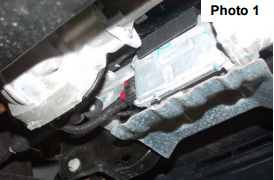
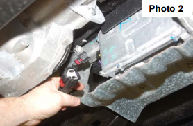
3. On 2011-up models and if equipped, remove the EPAS (Electronic Power Assist Steering) Plugs as shown located on the steering assembly by the front differential. See Photo 1 & 2. This must be done BEFORE installation is started.
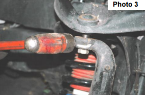
4. Place jack stand under the knuckle for support. Remove nut, using a 21mm wrench. Using a hammer hit the
knuckle as shown to allow the ball joint to separate from the upper control arm. See Photo 3. Do not allow the
knuckle to pull out far enough that it pulls the shaft out of the differential.
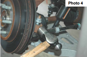
5. Using a 21mm wrench remove the nut from the steering linkage. Using a hammer hit on the side of the knuckle
as shown, where the steering linkage is connected and remove from knuckle. Push linkage forward to make
room for installation. Retain factory hardware. See Photo 4.
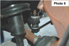
6. Remove the sway bar nut and bushings using a 15mm wrench. Retain factory hardware. See Photo 5.
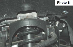
7. Using a 15mm wrench, remove the nuts on the upper strut tower that holds the assembly in place. See Photo 6.
One nut can be left on the upper bolts to hold the strut in place.
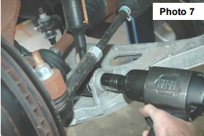
8. On 04-13 models using a 29mm socket, and 1 1/16”, wrench, remove the strut bolt from the lower control arm
and remove the strut assembly from the vehicle. Retain the factory lower bolt for reassembly. Note the direction
of the bolt for reassembly. See Photo 7.
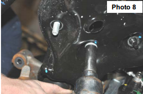
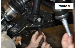
9. On 2014 models use a 18mm socket to remove the lower strut nuts from the bottom of the control arm. See
Photo 8. Next use a air chisel with a rounded blunt nose tool and dislodge the studs from the strut bar pin. Retain
factory hardware. See Photo 9.
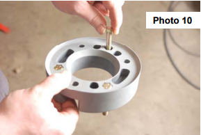
10. Locate the supplied 3/8”x2” bolts. Place into spacer as shown in Photo 10. It may be necessary to lightly tap the
bolts to get the hex bolt head into the hex hole.
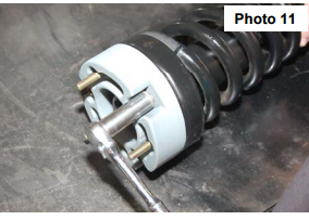
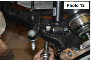
11. Install the new strut spacer on the strut with stock hardware using a 9/16” socket. Torque to 30 ft/lbs. See Photo
11. Install the strut assembly into the strut tower and secure with the supplied 3/8” flanged lock nuts using a
9/16” wrench. Torque to 30 ft/lbs. See Photo 12.
12. On 04-13 models install the lower strut bolt in the original position that it was removed. Using a 29mm socket,
and 1 1/16” wrench, torque to factory specs.
13. On 2014 models install the factory studs back into the barpin on the lower mount of the strut. It may be necessary
to hit the top of the strut with a hammer to seat the splines before tightening the factory nuts with a 18mm.
14. Using a floor jack, raise the lower control arm and connect the upper ball joint on the upper control arm to the
spindle. Using a 21mm wrench, torque to manufacturer specs. If ball joint turns while tightening, use a 3/8”
wrench to hold the ball joint.
15. Reinstall the steering linkage nut using a 21mm wrench.
16. Repeat steps 3-14 on opposite side of vehicle.
17. Using a 15mm wrench, reinstall sway bar bushings and nut using factory hardware. Torque to factory specs.
18. Install the wheels / tires, using a 21mm deep well socket.
19. If removed, reconnect the EPAS plugs.
20. Jack up the vehicle and remove the jack stands. Lower the vehicle to the floor and torque all bolts to factory
specifications.
21. Vehicle will have to have a front-end alignment.
22. If the rear block kit & shocks was ordered with the kit please proceed to the next section.
REAR INSTALLATION INSTRUCTIONS
1. Chock the front wheels.
2. Jack up the rear of the vehicle and place jack stands underneath the frame rail. Lower the
3. Remove the tires and wheels.
4. Remove rear shocks using a 15mm, and 18mm wrench. Save the stock hardware it will be used later.
5. Place the floor jack underneath the axle and remove the stock u-bolts. Lower the axle down to allow the blocks
to be installed in between the stock block and the spring perch. Install the new u-bolts and secure with fasteners
provided.
6. Assemble the rear shocks 650377, (RCX PART # 660564) and install in the stock position with stock hardware,
using a 15mm and 18mm wrench. Note: RCX 2.2 series shock absorbers are designed to run inverted with
the body of the shock absorber on the frame mount and the piston rod on the axle end.
POST INSTALLATION INSTRUCTIONS
1. Check all fasteners for proper torque. Check to ensure there is adequate clearance between all rotating, mobile,
fixed and heated members. Check steering for interference and proper working order. Test brake system.
2. Perform steering sweep. The distance between the tire sidewall and the brake hose must be checked closely.
Cycle the steering from full turn to full turn to check for clearance. Failure to perform inspections may result in
component failure.
3. Re torque all fasteners after 500 miles. Visually inspect components and re torque fasteners during routine vehicle
service.
4. Readjust headlights to proper settings.
MAINTENANCE INFORMATION
It is the ultimate buyers responsibility to have all bolts/nuts checked for tightness after the first 500 miles and then
every 1000 miles. Wheel alignment steering system, suspension and driveline systems must be inspected by a qualified
professional mechanic at least every 3000 miles

