 FREE 1 to 3-Day Delivery on Orders $149+ Details
How to Install a Rough Country Front 2-inch / Rear 2-inch Lowering Kit on your Ford F-150
Installation Time
3 hours
Tools Required
- 21mm Wrench
- 36mm Socket
- 18mm Socket
- 24mm Socket
- 10mm Socket/Wrench
- Needle Nose Pliers
- Impact
- Torque Wrench
- Cut Off Tool
- Floor Jack
- Jack Stands

Shop Parts in this Guide
FRONT INSTALLATION INSTRUCTIONS
1. Lift the front of the vehicle using a jack and support the vehicle with jack stands, so that the front wheels are off the ground
2. Remove the front tires/wheels.
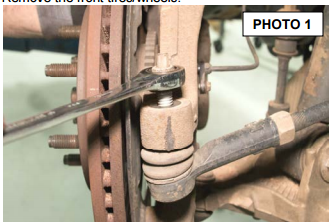
3. Using 21mm wrench, loosen Tie Rod End nut. Do not remove. See Photo 1.
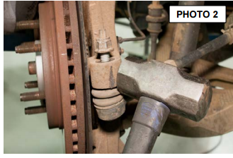
4. Using a hammer, strike the side of the knuckle to loosen the Tie Rod End. Remove nut and Tie Rod End from spindle. See Photo 2..
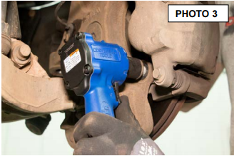
5. Using a 18mm socket remove the upper and lower caliper bolts. Remove caliper from spindle. Do not hang from brake line. See Photo 3.
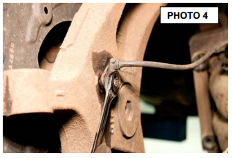
6. Using 10mm wrench, remove ABS wire from spindle. See Photo 4.
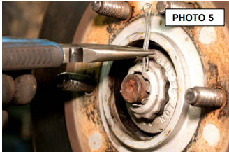
7. Remove cotter pin from axle shaft. See Photo 5.
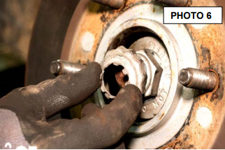
8. Remove locking nut. See Photo 6.
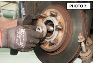
9. Using a 36mm socket remove stub shaft nut. See Photo 7.
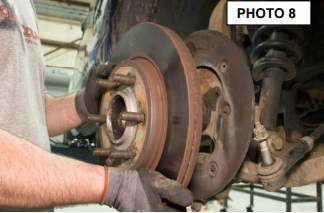
10. Remove rotor from spindle. See Photo 8.
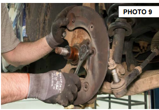
11. Using 10mm socket, remove dust shield bolts and dust shield. See Photo 9.
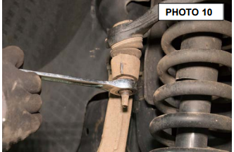
12. Using 21mm wrench, loosen upper ball joint nut. Do Not Completely Remove Nut. See Photo 10.
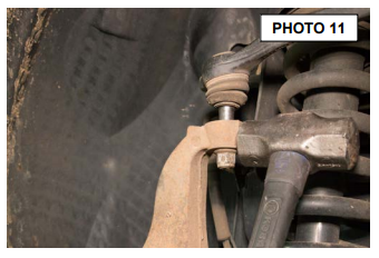
13. Strike rear of spindle at upper ball joint to loosen. Once the upper control arm pops up, remove nut from ball joint. See Photo 11.
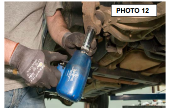
14. Using 24mm socket, loosen lower ball joint nut. Do Not Completely Remove Nut. See Photo12.
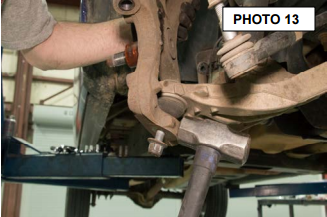
16. Strike rear of lower ball joint with hammer to release taper lock. See Photo 13.
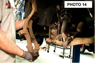
17. Remove spindle from upper and lower ball joints. See Photo 14.
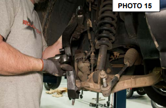
18. Place new lowered spindle on ball joints. See Photo 15.
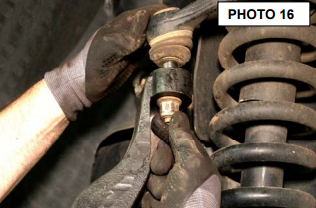
19. Place factory nut on upper ball joint and hand tighten. See Photo 16.
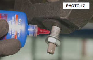
20. Apply a quality thread locker to lower ball joint. See Photo 17.
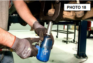
21. Using supplied nut and lock washer, tighten lower ball joint with a 24mm socket. Torque to 95 ft-lbs. See Photo 18.
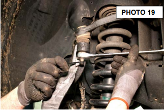
21. Using a 21mm wrench, tighten upper ball joint. Torque to factory spec. See Photo19.
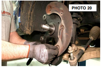
22. Replace dust shield using factory bolts. Tighten using 10mm socket. See Photo 20.
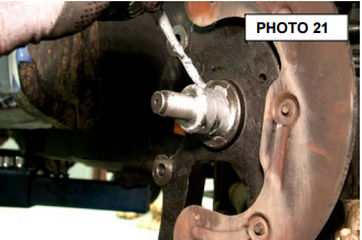
23. Apply anti-seize to end of stub shaft. See Photo 21.
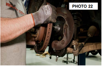
24. Install rotor back onto spindle stub shaft. See Photo 22.
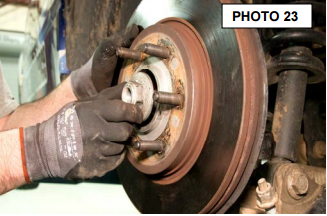
25. Using 36mm socket, install nut on stub shaft. See Photo 23.
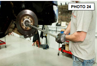
26. Torque nut to factory spec. See Photo 24.
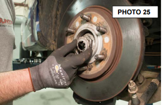
27. Install locking nut over stub shaft nut. See Photo 25.
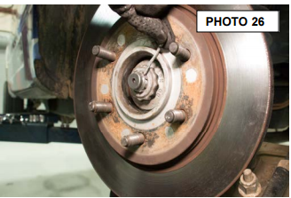
28. Install cotter pin in stub shaft. See Photo 26.
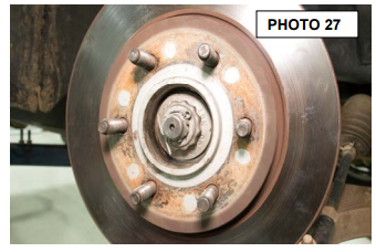
29. Bend ends of cotter pin around stub shaft. See Photo 27.
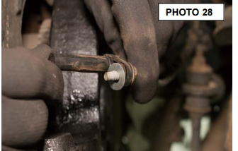
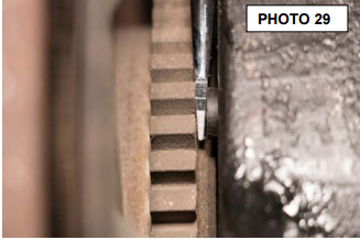
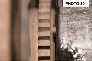
30. Using 10mm wrench, install ABS sensor into hole in spindle. See Photo 28.
31. Make sure there is a small gap between sensor and gear on rotor. See Photos 29 & 30.
27. Install brake caliper onto lowered spindle. See Photo 31.
28. Using 18mm socket, torque factory caliper bolts to factory spec. See Photo 32.
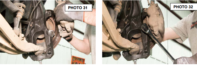
29. Using 21mm wrench tighten tie rod end factory nut. Torque to factory specs. See Photo 33.
30. Measure 1” from bottom and mark lower ball joint threads. See Photo 34.
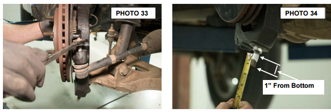
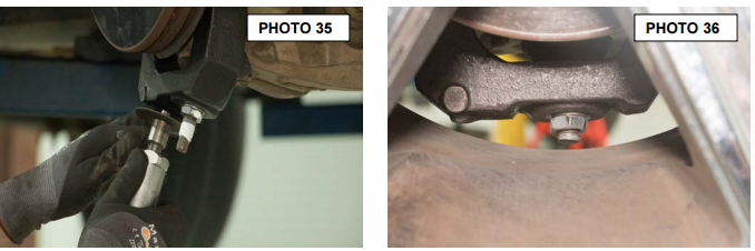
31. Using a cutoff wheel or reciprocating saw, cut lower ball joint at mark on threads. See Photo 35.
32. Install wheel and check clearance on lower ball joint. See Photo 36.
33. Repeat process for opposite side of vehicle.
Post Installation Instructions
1. Check all fasteners for proper torque. Check to ensure there is adequate clearance between all rotating, mobile, fixed and heated members. Check steering for interference and proper working order. Test brake system.
2. Perform steering sweep. The distance between the tire sidewall and the brake hose must be checked closely. Cycle the steering from full turn to full turn to check for clearance.
3. Re torque all fasteners after 500 miles. Visually inspect components and re torque fasteners during routine vehicle service.
4. Readjust headlights to proper settings and take truck in for a front-end alignment to a qualified alignment shop.

