FREE 1 to 3-Day Delivery on Orders $149+ Details
How to Install Modern Billet Stainless Steel Bumper Grille Overlay - Black on your F-150
Installation Time
1 hours
Tools Required
- Phillips Screw Driver
- Flat Screw Driver
- 5.5mm Wrench
- 16mm Wrench

Shop Parts in this Guide
INCLUDED COMPONENTS:
2 — "C" Brackets
4 — M4 Flange Nuts
2 — M10 x 25mm Hex Head Bolts
2 — M10 Flat Washers
2 — M10 Hex Nuts
PLEASE READ AND UNDERSTAND ALL INSTRUCTIONS BEFORE STARTING THE INSTALLATION. THE MANUFACTURER IS IN NO WAY RESPONSIBLE FOR ANY PERSONAL INJURY OR VEHICLE DAMAGE THAT MAY OCCUR DURING THE INSTALLATION.
1. Inspect product and check the components with items listed above.
2. Remove the license plate holder from vehicle by releasing (2) clips on the top and (2) clips on the bottom.
NOTE: You will not be re-installing the license plate holder back to the vehicle. Check if your local/state law requires a front license plate before installing Bumper Insert.
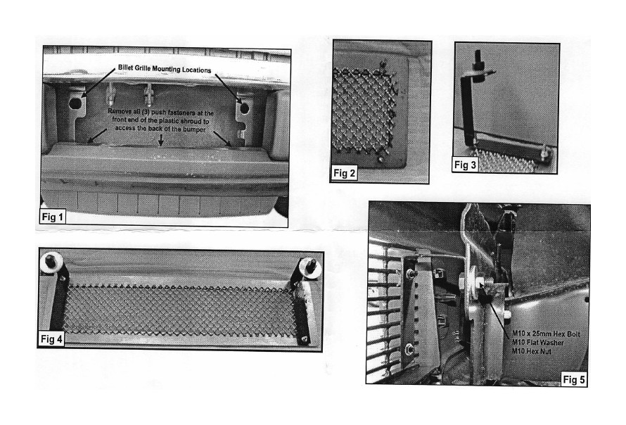
Once you have removed the license plate holder, locate and remove the (3) push fasteners at the front end of the bottom plastic shroud/rock shield (Fig 1), this will allow you to access the back of the bumper and attach the "C" Brackets to the Bumper.
3. Determine the top and bottom of the Bumper Insert (Fig 2). Attach both "C" Brackets to Bumper Insert using the included (4) M4 x 15mm Phillips Screws and (4) M4 Flange Nuts (Fig 3). Do not tighten at this time.
4. Position Bumper Insert assembly (Fig 4) into bumper cavity. Attach the "C" Brackets to bumper using the included (2) M10 x 25mm Hex Head Bolts, (2) M10 Flat Washers, and (2) M10 Hex Nuts (Fig 5). Do not tighten at this time.
5. Center and align Bumper Insert one last time and then tighten all hardware at the same rate.
6. Re-install plastic shroud/rock shield using the factory push fasteners.
7. Do periodic inspections to the installation to make sure that all hardware is secure and tight.