FREE 1 to 3-Day Delivery on Orders $149+ Details
How to Install Rough Country 4 in. Suspension Lift Kit w/ Lifted Struts (09-13 4WD, Excluding Raptor) on your Ford F-150
Installation Time
1 days
Tools Required
- 5mm Allen Wrench
- 8mm Allen Wrench
- 8mm wrench /socket
- 10mm wrench /socket
- 12mm Wrench
- 13mm wrench / socket
- 15mm wrench /socket
- 16mm wrench /socket
- 18mm wrench /socket
- 19mm wrench /socket
- 21mm wrench /socket
- 22mm wrench /socket
- 24mm wrench /socket
- 30mm wrench /socket
- Floor Jack
- Jack stands
- Reciprocating Saw
- Hammer
- 9/16 wrench /socket
- 1 1/16” Wrench
- Drill
- 1/4” Drill Bit
- 5/8” Drill Bit
- 41/64” Drill Bit
- 11/32” Drill Bit

Shop Parts in this Guide
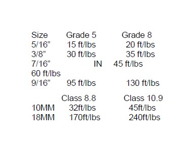
Torque Specs:
INSTALLATION INSTRUCTIONS
1. Chock the rear wheels and jack up the front of the vehicle.
2. Place jack stands under the frame rails and lower onto jack stands.
3. Remove the wheels/tires using a 21mm socket.
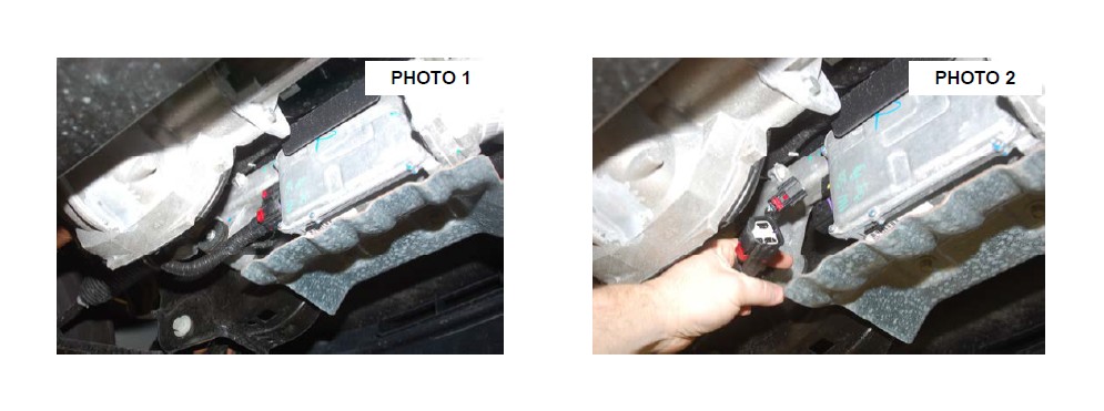
4. On 2011-14 models and if equipped, remove the EPAS (Electronic Power Assist Steering) Plugs as shown located on the steering assembly by the front differential. See Photo 1 & 2. This must be done BEFORE installation is started.
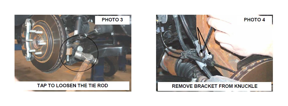
5. Remove tie-rod end using a 21mm wrench. Using a hammer hit the side of the knuckle to pop tie-rod out. Photo 3.
6. Remove the ABS and brake line bracket from the knuckle using a 8mm wrench for the ABS wire and a 10mm wrench for the brake line bracket. Retain hardware for reuse. See Photo 4.
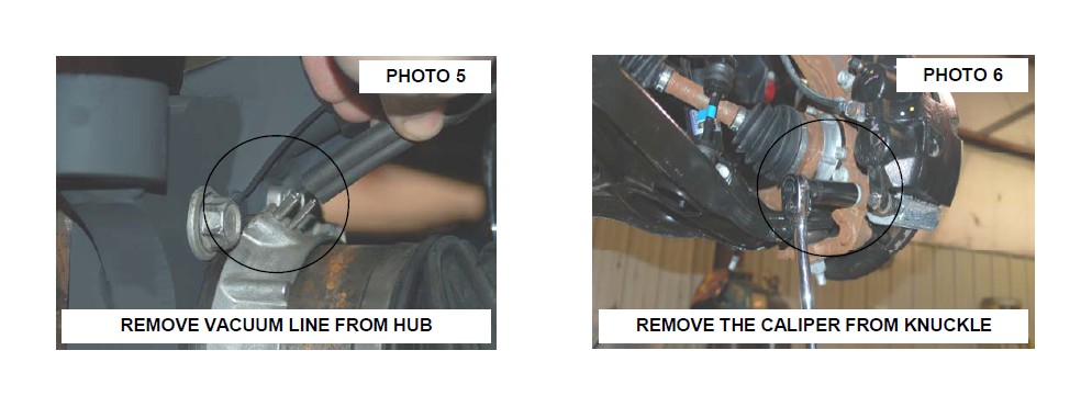
7. Remove the vacuum line from the hub. See Photo 5.
8. Using a 19mm socket & 21mm wrench, remove brake caliper as shown in Photo 6. Hang caliper out of way. Do not let caliper hang by brake hose as this will damage hose. Retain hardware for reuse. Remove rotor.
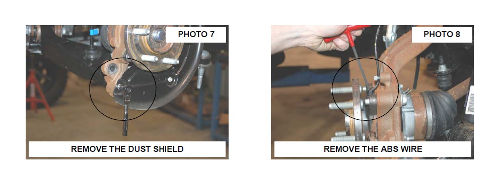
9. Remove the dust shield using a 8mm socket and dust cap. See Photo 7.
10. Remove the ABS wire from the bearing assembly using a 5mm allen wrench. See Photo 8.
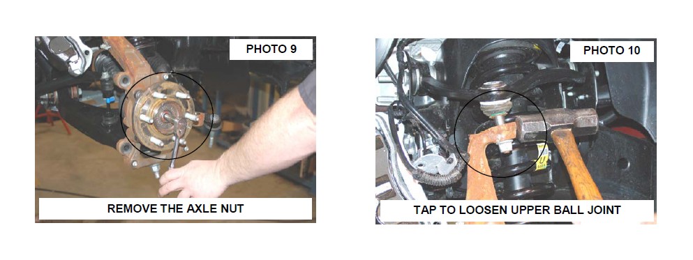
11. Remove the axle nut using a 13mm socket. Retain hardware for reuse. See Photo 9.
12. Loosen the upper ball joint nut using a 21mm wrench. Tap lightly with a hammer to release ball joint from knuckle. See Photo 10.
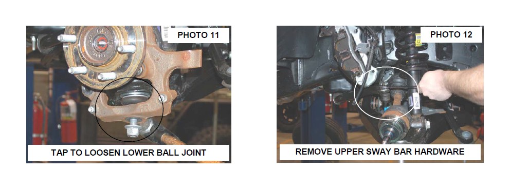
13. Loosen the lower ball joint using a 24mm wrench. Tap lightly with a hammer to release ball joint from knuckle. See Photo 11.
14. Remove the upper and lower ball joint nuts and remove the knuckle from the vehicle.
15. Remove the sway bar links from the sway bar using a 19mm wrench. Retain hardware for reuse. See Photo 12.
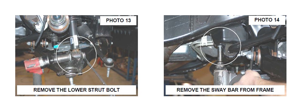
16. Remove the lower strut bolt using a 30mm socket and 1 –1/16” wrench. See Photo 13. Retain hardware for reuse.
17. Remove the sway bar from the frame mount using a 15mm socket. Please note the position that the sway bar is installed from the factory to make sure it is reinstalled correctly. Retain hardware for reuse. See Photo 14.
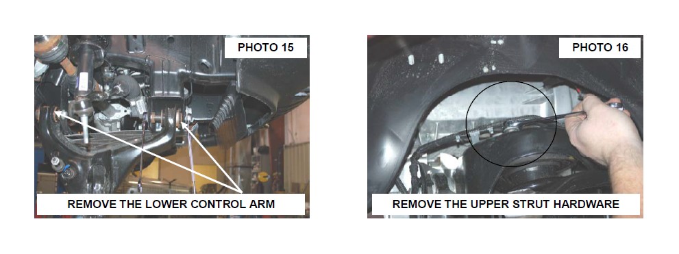
18. Remove the lower control arm using a 21mm and 1-1/16” wrench. Retain hardware for reuse. See Photo 15.
19. Remove the strut from the upper mount using a 15mm socket / wrench. Retain hardware for reuse. See Photo 16.
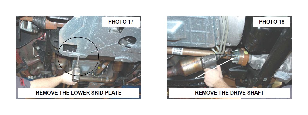
20. Remove the lower skid plate by removing the 4 bolts using a 13mm socket. See Photo 17.
21. Remove the driveshaft from the front differential using a 10mm socket. See Photo 18. Secure driveshaft out of the way.
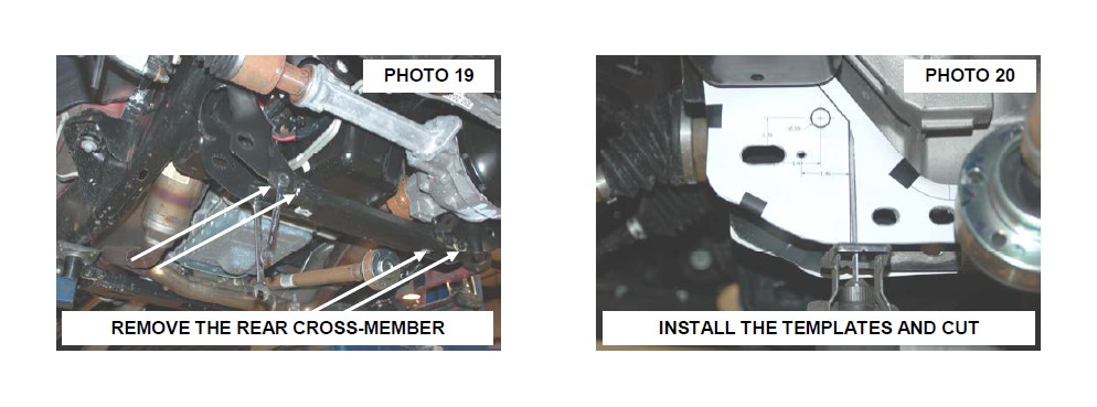
22. Remove the stock rear cross-member using a 15mm & 18mm socket. Retain hardware for reuse. See Photo 19.
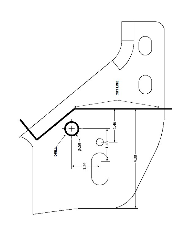
23. Tape supplied cutting template on front and back side of the driver side lower cross-member mount. Using template as a guide, trim cross-member mount to allow the differential to be removed. See Photo 20.
24. Remove the differential vent tube from the differential.
25. Support the differential using a floor jack and remove the upper driver side differential bolt using a 18mm wrench. Retain hardware for reuse. See Photo 21.
26. Remove the passenger side differential bolt using a 18 & 21mm wrench. Retain hardware for reuse. See Photo 22.

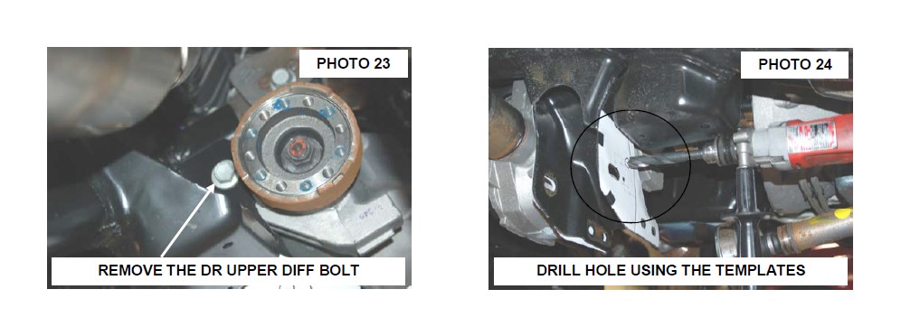
27. Remove the lower rear driver side differential bolt using a 21mm socket / wrench. Lower and remove the differential from the vehicle. See Photo 23.
28. Complete the trimming of the frame on the driver side using the template and drill a pilot hole in the center using 1/4” drill bit. Finish the hole shown in Photo 24 using a 5/8” drill bit.
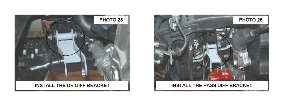
29. Install the upper differential drop bracket on the driver side using the stock hardware. See Photo 25. Do not tighten at this time.
30. Install the passenger differential bracket using the stock hardware. Photo 26. Do not tighten at this time.
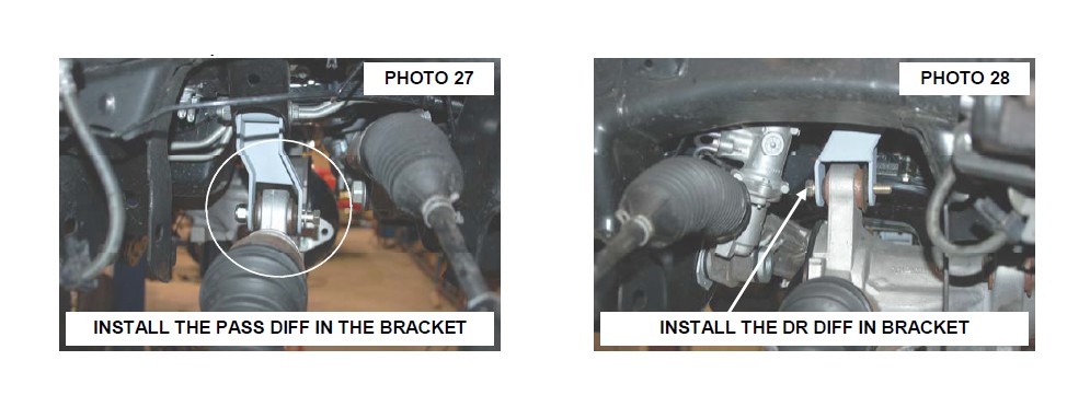
31. Install the differential in the new brackets with the supplied hardware. Install the 9/16” x 4” bolt, washers & nut in the in the passenger side mount. See Photo 27.
32. Swing the differential up to the drive and install the 9/16” x 4” bolt, washers and nut from the front to rear. NOTE:
The differential mounts will need to be loose to push the differential to the passenger side in order to clear the rack and pinion and install the bolt. See Photo 28.
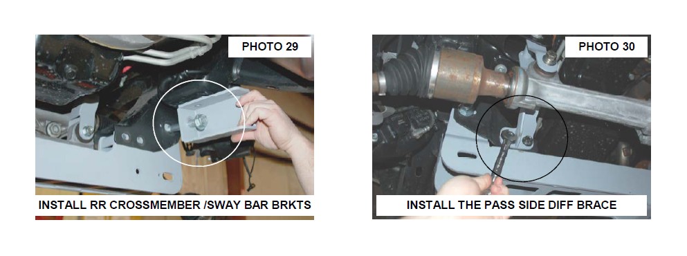
33. Install the rear cross-member and sway bar mounts on the driver and passenger side as shown in Photo 29. The supplied 18mm x 160mm bolt will install through the sway bar bracket and rear cross-member, securing it to the stock location. Do not tighten at this time.
34. Install the passenger side differential brace as shown in Photo 30 using the stock cross-member hardware. Do not tighten at this time.
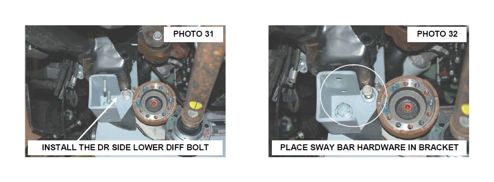
35. Install the supplied 9/16” x 4 1/2” rear differential bolt through the sway bar mount and new differential mount. See Photo 31. Do not tighten at this time.
36. Reinstall the stock sway bar flag bolts in the new sway bar drop bracket to keep the bracket aligned while tightening the cross-member bolts. See Photo 32.
37. At this time tighten all diff bolts using 18mm socket / wrench for the upper diff bolts and a 21mm & 22mm socket / wrench for the new supplied lower diff bolts. Also tighten the passenger side diff brace hardware using a 15mm & 18mm socket /wrench.
38. Reinstall the vent tube on the differential.
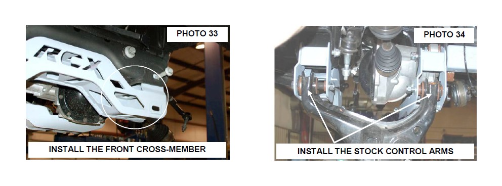
39. Install the front cross-member using the factory hardware. See Photo 33. Do not tighten at this time.
40. Install the lower control arms using the supplied 18mm x 160mm cam bolts, washers and nuts. See Photo 34.Do not tighten at this time.
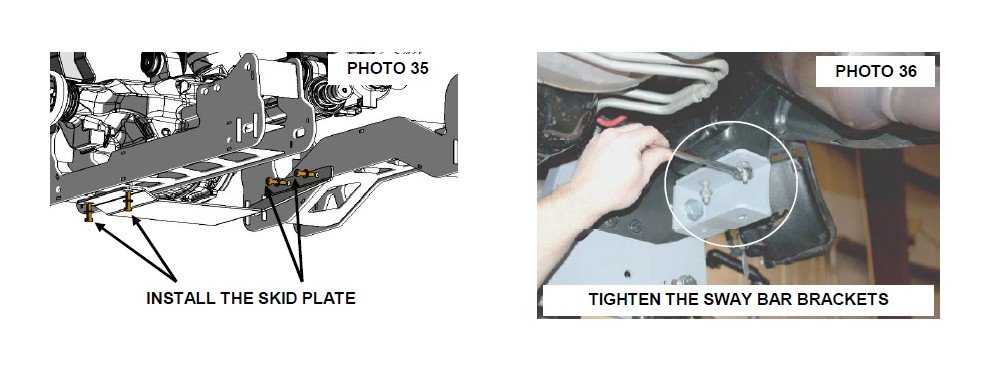
41. Install the new skid plate in the front and rear cross-members threaded holes using the supplied 3/8” x 1” bolts, washers. See Photo 35. Tighten using a 9/16” socket.
42. Tighten all upper cross-member bolts using a 21mm, 1 1/16” socket and 1 1/16” wrench.
43. Tighten the sway bar drop mounts to the frame using the factory hardware with a 15mm socket. See Photo 36.
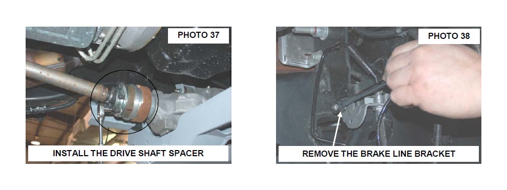
44. Install the drive shaft spacer with supplied 10mm x 80mm hardware. See Photo 37. Tighten using a 8mm allen wrench.
45. Using a 10mm wrench remove the brake line bracket from the driver and pass side frame. See Photo 38.
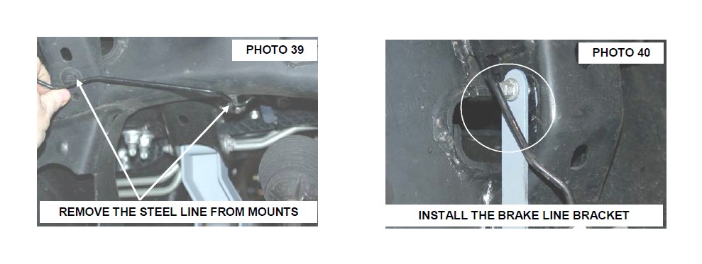
46. On the passenger side remove the brake line from the two factory clips. See Photo 39.
47. Install the new brake line bracket on the driver and passenger side with the stock hardware. See Photo 40.
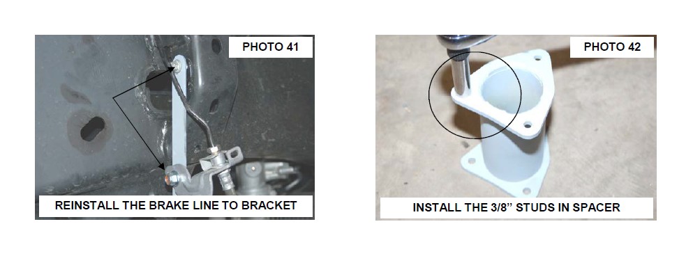
48. Install the factory passenger side brake line in the new bracket using the supplied 5/16’ x 3/4” bolt, washer and nuts. See Photo 41.
49. On the driver side, pull slightly on the brake line to allow the line to be installed on the new bracket. Secure the brake line to the new bracket with the supplied 5/16” x 3/4” bolt, washers and nut.
50. Using a 13mm socket / wrench, tighten the supplied brake line hardware and 10mm for the stock hardware.
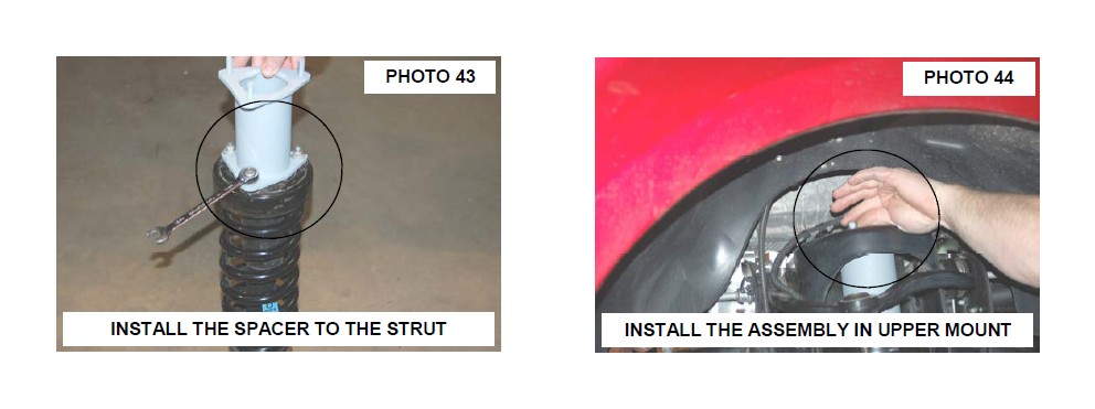
51. Install the supplied 3/8” studs in the strut spacers with a 9/16” wrench as shown in Photo 42.
52. Using the stock hardware, install the strut spacers on the struts. Tighten using a 15mm socket. See Photo 43.
53. Install the strut with strut spacers installed in the stock upper mount. Secure with supplied 3/8” nuts, washers and lock washers. See Photo 44. Do not tighten at this time.
54. Install the lower strut in the lower control arm using the factory hardware. Tighten using a 30mm and 1-1/16” wrench.
55. Tighten upper strut mount hardware using 9/16” wrench.
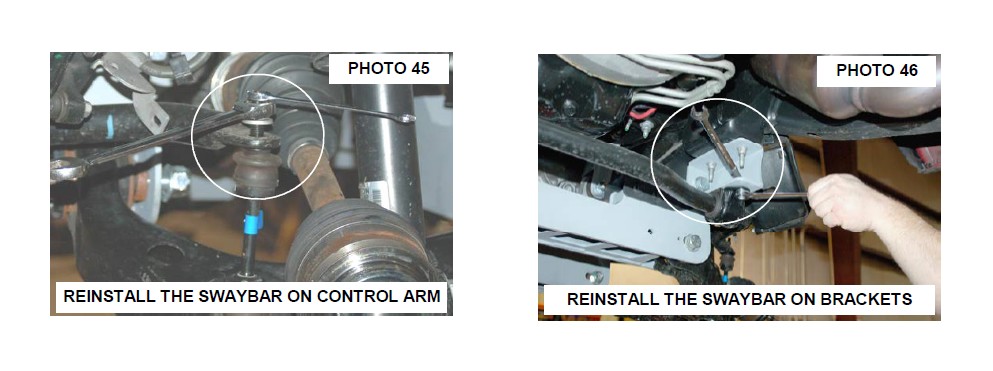
56. Install the sway bar body on the sway bar links located on the lower control arms. Install nut to hold the sway bar in place but do not tighten at this time. See Photo 45.
57. Swing up the sway bar and install on the sway bar drop brackets using the supplied 3/8” x 1” bolts, washers and nuts. Tighten using a 9/16” on the sway bar drop hardware and 18mm wrench on sway bar links on the lower control arms. See Photo 46.
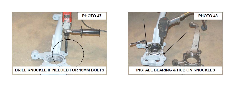
58. Depending on the brake caliper bolt size, the knuckle may need to be drilled. If the stock bolt is 16mm the caliper mounting location will need to be enlarged using a 41/64” drill bit. Trial fit the stock caliper bolts to make sure the caliper needs to drilled before drilling. See Photo 47.
59. Remove the stock bearing assembly from the stock knuckle using a 18mm for the bearing and a 8mm for the locking hub mechanism. Install the bearing assembly and hub mechanism using the stock hardware. Tighten using a 18mm and 8mm wrench. See Photo 48.
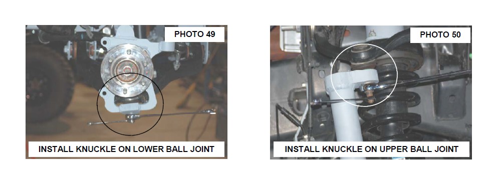
60. Install the new knuckles using the stock hardware on the lower ball joints, making sure the half shafts are installed in the bearing assembly. Tighten using 24mm and a 12mm wrench. See Photo 49. Do not use air impact on the upper and lower ball joint, tighten with hand tools.
61. Install the half shaft axle nut and lightly tighten with HAND TOOL only!!
62. Install the knuckle on the upper ball joint with the stock hardware and tighten using a 21mm and a 10mm wrench. See Photo 50. Do not use air impact on the upper and lower ball joint, tighten with hand tools.
63. Reinstall the locking hub vacuum hose as shown in Photo 51 on the hub mechanism and install the ABS wire on the bearing assembly using a 5mm allen wrench. See Photo 52. NOTE: The factory dust shield will not be reused.
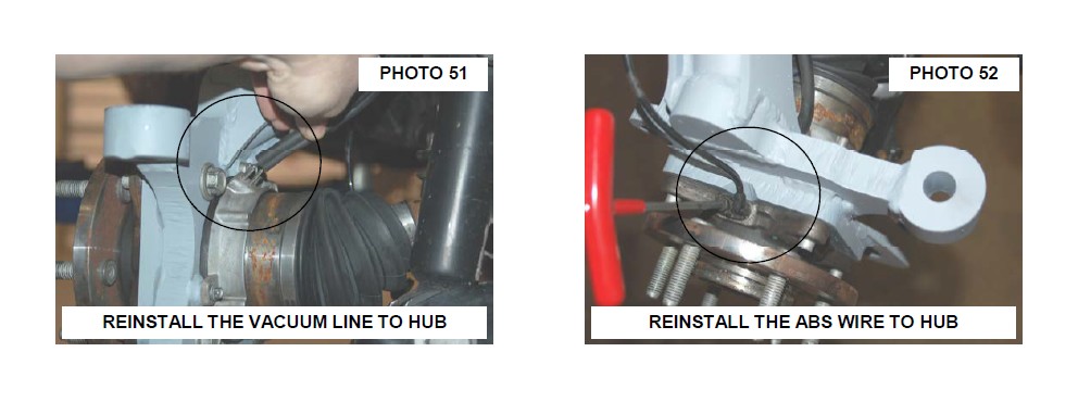
64. Tighten the axle nut using a 13mm wrench and install the dust cap.
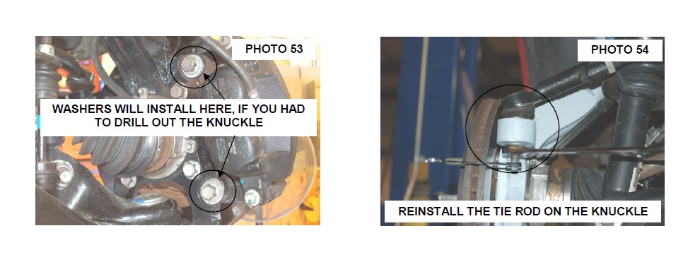
65. Install the rotor and caliper on the knuckle with the stock hardware using a 19mm or 21mm wrench. If you have to drill the knuckle for 16mm caliper bolts, it will be necessary to use the 5/16” thick washers on the head of the caliper bolts. Failure to use these washers on the 16mm bolts will allow the caliper bolt to protrude on the rotor side and can cause clearance issues. Tighten hardware. See Photo 53.
66. Make sure the vacuum hose and ABS wire are out of harms way. Using the supplied zip tie, secure the vacuum hose and ABS wire to the knuckle neck.
67. Install the tie rod end in the knuckle and tighten using a 21mm and 10mm wrench. See Photo 54. Do not use air impact on the upper and lower ball joint, tighten with hand tools.
68. Install the tires and wheels using a 21mm socket. Remove the jack stands and lower the truck to the ground.
69. Tighten the lower control arm bolts using a 1-1/16” wrench and socket. Torque to 200 ft/lbs.
REAR INSTALLATION
1. Chock the front tires and jack the rear the rear end up. Put jack stand under the frame rail and lower truck onto jack stands.
2. Remove tires and wheels using a 21mm socket.
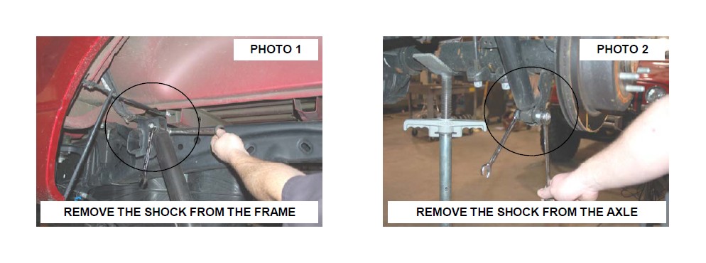
3. Remove rear shocks from the upper and lower mount using 18mm and a 15mm wrench. See Photo 1 & 2. Retain the stock hardware.
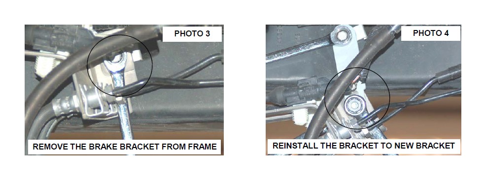
4. Using a 10mm wrench, remove the brake line assembly on the inner driver side frame rail. See Photo 3.
5. Install the brake line extension bracket on the frame using the stock hardware and tighten using a 10mm wrench. See Photo 4.
6. Install the brake line assembly to the new bracket using the supplied 3/8” x 1” bolt, washers and nut. Tighten using a 9/16” socket and wrench. See Photo 4.
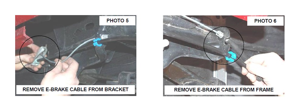
7. Separate the e-brake cable as shown on the drivers side and remove the e-brake cables from the frame mount as shown in Photo 5 & Photo 6.
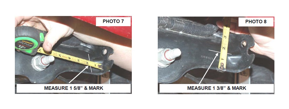
8. To install the new e-brake bracket measure from the rear measure 1 5/8” and from the bottom measure up 1 3/8” and mark hole to be drilled. See Photo 7 & 8.
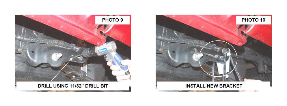
9. Drill hole using a 11/32” drill bit. See Photo 9.
10. Install the new bracket as shown with the supplied 7/16” x 1” bolt, washers, nut in the factory hole and 5/16” x 3/4” bolt, washer and nut in the drilled hole. See Photo 10. Tighten using a 19mm and 13mm socket / wrench.
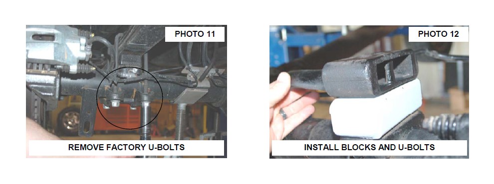
11. Using a jack support the rear end and remove U-bolts using a 21mm socket. See Photo 11.
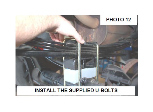
12. Install new block as shown in Photo 12 with the stock block on top of the new block. Raise the axle using the jack until axle pins line up with hole and pin in block.
13. Install the axle u-bolts and tighten using a 22mm socket.
14. Secure block to axle and spring installing the 9/16 x 11” square U-bolts as shown. Tighten nuts to factory torque using a 7/8” socket. See Photo 12.
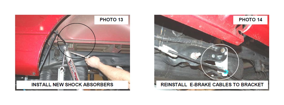
15. Install the new RCX 2.2 shock absorbers in the upper and lower mounts using the stock hardware. Tighten using a 18 and 15mm wrench. See Photo 13.
16. Install the tire and wheels.
17. Raise up the rear of the vehicle and remove the jack stands. Lower the vehicle to the ground.
18. Install the e-brake cable in the new mount and reattach the ebrake cables on the frame. See Photo 14.
POST INSTALLATION INSTRUCTIONS
1. Check all fasteners for proper torque. Check to ensure there is adequate clearance between all rotating, mobile, fixed and heated members. Check steering gear for interference and proper working order. Test brake system
2. Perform steering sweep. Check to ensure brake hoses have sufficient slack and will not contact rotating, mobile, or fixed members, adjust lines/brackets to eliminate interference and maintain proper working order. Failure to perform inspections may result in component failure
3. Readjust headlights to factory settings
4. Have vehicle aligned by a certified alignment professional.
5. Re-torque all nuts, bolts, and especially u-bolts after the first 100 miles, again after another 100 miles and then check periodically thereafter
6. All components must be retightened after 500 miles, and every three thousand miles after installation.
CUTTING / DRILLING TEMPLATE—FR SIDE OF DRIVER CROSS-MEMBER
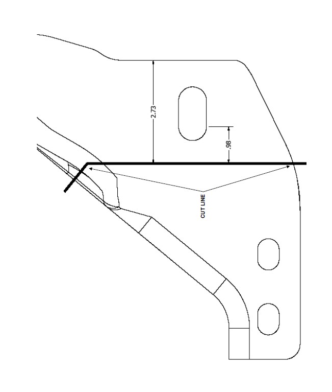
CUTTING / DRILLING TEMPLATE—REAR OF DRIVER SIDE CROSS-MEMBER