Talk to a F-150 Sales Tech
1-888-706-1096
M-F 8:30A-11P, Sat-Sun 8:30A-9P
$20K Sweeps! 10 Chances to Win! Enter Daily >

Mammoth 3-Inch Front Leveling Kit (04-13 2WD/4WD F-150, Excluding Raptor)

Item T542568
Verify parts fit and get product recommendations.
F-150 Sales Techs: Connect Now M-F 8:30A-11P, Sat-Sun 8:30A-9P
$0.00
On Sale

$55.99 (pair)

FREE Shipping on orders over $119 Market Price $72.99 You Save 23% ($17.00) Up to 10% off for Military & First Responders! See Details

Will this fit your Vehicle?

Select a different vehicle Help?
Update or Change Vehicle
Ship to: Ashburn - 20149
Sorry, please enter a valid US or CA postal code
We're sorry, zip can't be updated at this time.
Recommended Install Shops
How It Works
Install Shops are available near Ashburn - 20149

Add Local Shop Installation

Total cost of service $499.00
    Create a list
    Add to New List

    Saved - View your saved items

    We're sorry. We couldn't save this product at this time.

      Video Review & Installation

      Hey guys, Adam here with americantrucks.com. Today, we're taking a closer look at and installing the Mammoth 3-inch Front Leveling Kit. This is available for the '04 to '13 2-wheel drive and 4-wheel drive F-150s, excluding Raptors. You should be checking out this particular leveling kit from Mammoth if you're looking to accomplish a number of things. First and foremost, you might be looking to fit bigger wheels and tires comfortably in those wheel wells of your F-150. You might be looking to level out the truck's appearance, getting rid of that factory rake. And finally, you might be looking for a little bit of additional ground clearance at the front end for some light off-roading situations. This is especially gonna be useful for the F-150 owners who may have a little bit of added weight at the front end that a simple 2 or even 2.5-inch leveling kit might not actually level up the truck with. If you have something like an off-road front bumper made of heavy steel, maybe you have a winch or even a snowplow in the wintery months at the front end, those things will sag the front end down. Having the larger 3-inch kit will keep that truck leveled out regardless of that front end weight.Now when you start getting into the bigger leveling kits, somewhere around 3 inches, like this guy here, it does start to put more stress on some of the suspension components. CV angles are gonna be a little bit of a harsher angle. Your upper control arm ball joint is at a tougher angle. So, it is worth mentioning that with a 3-inch, the larger leveling kit, there is some more premature wear on those suspension components. With that said, you might consider upgrading some components, like getting a better upper control arm that's built to handle lifted applications for greater wheel articulation and one that might even reduce some of the downward suspension travel. Now that's not required but it is recommended when getting into the larger kits here.Now as far as ride quality because it is a little bit of a larger kit here it may result in somewhat of a stiffer ride quality at the front end, not necessarily a poor ride quality, but it will change the ride quality just a little bit. Now the 3-inch kit here is also great for fitting those bigger wheels and tires. As you know, fitting up to 35s can be very difficult. Even with a 2 or even a 2.5-inch leveling kit. In some cases, you might have some rubbing. Three-inch leveling kits here allow you to have a little bit of extra room to fit those meatier tires or even wider tires with a more aggressive offset. Now depending on your aggressive offset, there may be some slight rubbing at full lock, but nonetheless, you can fit up to 35s with this 3-inch kit. In addition, this kit is a CNC machined billet aluminum, making it a little bit cheaper than some of the heavy-duty steel options. This one here uses a black anodized finish to give it some corrosion and rust resistance. And personally, I actually favor more towards these billet aluminum kits rather than the more expensive steel kits just because number one, steel is gonna be more susceptible to rust, especially if you're located in wintery weather areas like we are here. We see a lot of road salt. It can take its toll on suspension components. Having that billet aluminum takes just a little bit more stress off you. Now with that, the black anodized finish does add that durability. Now the kit comes in right around 30 bucks making it one of the most affordable mods you can do to your truck, believe it or not. Just because it's a 3-inch doesn't mean the price reflects that. It's coming in right around 30 bucks making it super affordable.The install for this, I am giving three out of three wrenches on our difficulty meter. There is no cutting, no permanent modification required but some specialty tools are recommended to do the job properly. Following Ford's instructions on how to take apart the suspension at the front end, you are gonna have to pull vacuum from the 4-wheel drive actuator for 4-wheel drive equipped models. Two-wheel drive equipped models, different story, and I'll talk about that when we get to the installation there. But just know that it can increase the difficulty of the install. The install will take you about two, maybe three hours from start to finish to get the front end done. I'm gonna walk you through every step of the process here. Let's get started.Tools used in this install include an air impact gun, an impact gun and/or a ratchet, swivel socket, 30-millimeter deep socket, 15/16, 27, 21, 19, 17, 13, 10, and 8-millimeter deep sockets, 8-millimeter hex socket or Allen key, 1/2-inch ratchet, hammer, vacuum pump for 4-wheel drive actuators, 15-millimeter ratcheting wrench is heavily recommended and a pry bar.All right, guys kicking off the uninstall here. Before we get started, I wanna make a quick mention that our '13 F-150 we're gonna be working on here has its upper control arm replaced. Yours might look a little different than the one we have here but just know that the process is exactly the same. And this upper control arm here is not gonna change the height whatsoever. So, that's out of the way. Let's get started with taking our brake line and our ABS line off of the knuckle and up here towards the frame just to make sure we have a little bit more slack on it.All right, now there's two brackets here on the side, one for the ABS line and one for the brake line. The brake line is a 10-millimeter bolt. This guy's an 8-millimeter. I have the 10-millimeter here. Let's get that one out of the way first. Now what I like to do is disconnect the bracket and then I'm just gonna put the bolt right back on just so we don't lose it. All right, so now I switched over to an 8-millimeter to do the ABS. All right, now following those brake lines back up here to the frame, there's one more 10-millimeter. So let's switch back over and get that guy off. All right so now all this has a bunch of slack and we're not gonna be putting excess pressure on it.All right now we have to get our caliper out of the way. Now in order to do that, I'm gonna use a 19-millimeter socket and a swivel socket along with my air gun to pop this bolt off and the bottom one down here. Now it's gonna remove the entire caliper from the bracket. All right so now I have my caliper hanger and this is gonna help hang the caliper up onto the frame so we're not putting stress on the brake lines as well. Gonna put that guy there. From here, we're gonna work off the caliper.Next step, of course, is to get the rotor out of the way. Now, in most cases, if you pull on it, the guy's probably stuck on there. There's a little rust and corrosion on the inside of that hub there, in which case you can grab a mallet and carefully tap on the outside of the rotor here to dislodge it. All right, there you go. Now we can set this aside. Now we're gonna switch back over to the 8-millimeter socket and get our dust shield out of the way. There's three bolts holding this guy on, two on the bottom, one at the top. All right now I'm gonna grab a 3/16 hex socket and we're gonna get the ABS sensor off of the hub. So that guy comes out, very small screw. You're gonna carefully pull that guy out of the hub. We're just gonna let that guy hang off to the side. That's an 18-millimeter deep socket we're gonna use. And I'm also gonna use a swivel socket, just to make life a little bit easier with this air gun. With that guy loosened up, I'm actually just going to keep this on a couple of threads. We wanted to make this loose so that the lower control arm can drop down a little bit.Next up, let's loosen up the upper control arm castle nut. Now this guy here has a retainer pin in the middle, which yours may also be bent on the other side, so you may need to unbend it. And you're basically just gonna pull it out from the middle of the castle nut. I'm gonna set this aside. Now we're gonna use an 18-millimeter deep socket, again, the swivel. So basically the same assembly we used for the sway bar end link and loosen this guy up. Now what I'm gonna do is just take that castle nut and thread it on a couple of threads because we still have to dislodge the upper control arm from the knuckle and we wanna make sure this is on to catch it so it doesn't pop out. So now, let's get our tie rod end off. Now I'm gonna use a 21-millimeter deep socket to loosen up this nut. Again, the same thing, thread on a couple of threads. All right, same concept applies to the tie rod end. We had the nut on a couple of threads. I'm gonna use a mallet to tap on the backside here right in the steel portion so I don't damage the ball joint there and we'll have that dislodged from the knuckle as well. So if you need to, you can grab a ball-peen hammer and tap right on the side of the knuckle there as you just saw, and that should dislodge it. All right, now we're essentially gonna do the same thing for the upper control arm. You can use a ball-peen hammer to hit right up against the knuckle there. You do not wanna hit the upper control arm ball joint. Make sure you're focusing right there. We're gonna do the exact same thing we just did but to the lower control arm to knuckle joint right here with this 15/16 nut. Perfect. So it doesn't look like we're gonna need to hammer that. It looks like it dislodged. If yours does not dislodge like this one just did, you can use a hammer and do the same process, hitting this, making sure you're not damaging the actual ball joint there.Now this next step is a little bit more unique to the 4-wheel drive guys. Now, if you have 4-wheel drive, we have to pull vacuum from the 4-wheel drive actuator to disconnect the CV axle from the whole knuckle and hub assembly. The reason we're doing that is to avoid damaging the 4-wheel drive actuator and/or the CV axle when we're lowering the lower control arm and lifting the truck. Putting that at such a high-stress angle, pulling down on it in order to get the strut in and out can cause damage to the 4-wheel drive, which is why you're gonna need this tool here, which is a vacuum pump, which is gonna help pull vacuum from the 4-wheel drive actuator. We're gonna pull 24 pounds of vacuum using this gauge here. We're gonna disconnect everything we need to, set this aside and pull the entire hub and knuckle assembly off.All right, now the vacuum line here is right above where the [inaudible 00:09:46] connect to the hub. Just gonna pull that guy straight back and disconnect. I'm gonna take my pump and connect the hose to the bigger fitting. All right, I'm gonna pump this and focus on my gauge here to 24 pounds of pressure. That's gonna be the sweet spot right there. Now I'm gonna carefully set this aside without releasing the pressure. I'm gonna seat that right on our lower control arm there. Now with that pressure pulled, I'm basically gonna disconnect the upper control arm and the tie rod end, and then use a 13-millimeter socket to remove the axle nut. From there, I'll pull the CV axle out of the hub. Now because we relieved that pressure, we'll be able to slide that right out. From there, I'll remove the lower control arm nut and pull the entire knuckle assembly off the truck.All right, so this is gonna be kind of one motion so I'm gonna take first off the upper control arm off. Keep that guy down there. I'm gonna put this nut back on just so we don't lose it. And our tie rod end is coming next. That we did not want to happen. So we're gonna bring this guy back up. Still holding pressure, which is awesome. Perfect. Tie rod end nut is gonna go back here. Next thing I'm gonna do is use a 13 socket to remove the axle nut, pull the CV axle out of the hub and remove the lower control arm bolt. All right, so you can see this guy slides right out, lift up here, remove the lower control arm nut. Just gonna drop that to the ground. And this whole assembly is going to come with me. Just like that. Pull the pump with me and there you have it.All right, so here I have the entire hub and knuckle assembly on the ground and I wanna show you guys what the reverse side looks like. This is where the CV axle actually connects to the hub. Inside is our 4-wheel drive actuator. And you can see the teeth going all the way around. I still have our pump hooked up. So what I wanna do is I'm gonna show you guys what this actually does to give you some context as to why we need to do it. As it sits, I relieve the pressure. There's no... I did not remove any vacuum from this. Here I'm gonna pump. And as I pump, you can see the teeth start to lift up. Pulling vacuum, the 24 pounds that we just did, as you saw lifted the teeth up. That disengages the 4-wheel drive actuator from the CV axle and allows us to slide it out. Now if I were to relieve that, you'll see this seat back down and that would in theory, engage the 4-wheel drive. So, pumped up and relieved. You can see it sinks back down into the hub. So this just gives you some context as to why we need to do that.Next thing we're gonna remove our bottom strut bolt from the lower control arm. The nut is a 30-millimeter and the bolt head is a 27. So you're gonna need some specialty sockets. I've got my 27 short socket on my 1/2-inch ratchet and my 30 socket on my air gun. There it is. I can set that aside. All right, next, we can pull the bolt out. All right, next up, we can remove the three top strut tower nuts. These are 15 millimeters. I'm gonna use a ratcheting wrench, definitely recommend this. And you're gonna get these guys off. All right now to get our strut assembly out, I'm gonna use a pry bar right underneath of that, right in this little seat here in the lower control arm. Now basically gonna pry up an outward to get it out of its seat. Slide it down. Now we can set this guy aside.All right, next up here, guys, let's assemble our 3-inch spacer from Mammoth onto our strut assembly. Before we do that, we have to install the 8-millimeter hex screws into this as our new studs. Now these new studs included in the kit will hold the entire assembly to the strut tower in the truck. The factory studs on your factory strut top hat are gonna hold the spacer to the strut. So grab these screws included in the kit. You're gonna find which way is up. The smaller holes where you can see the threading is up. Flip that upside down and those smaller holes get a little bit bigger. What you're gonna basically do is take this screw, set that through and thread it in by hand for those smaller threaded holes. The larger ones will seat into the factory studs. Once you have those threaded in a bit, you're gonna grab your 8-millimeter hex socket and tighten them down. Do that for the rest of them. All right, from there, you can start assembling this onto the strut. Now it only goes on one way, of course, make sure those studs are facing up. If they're not lining up, just keep rotating it until it drops in. Grab a 17-millimeter socket along with the nylon lock nuts included in the kit. And before I even put it on an impact gun or a ratchet, I'm gonna drop the nylon lock nut onto the stud and just thread this guy on just using the socket itself. Do that for the rest of them. All right, with them tightened down, put this on your impact gun and tighten them up. Perfect. Now we can throw this back in the truck.All right, so now you can throw this assembly back into the truck, lining them up to the top of the strut tower. All right, with those guys through, take your factory nuts and thread them onto the top to hold it in place. Do the same thing for all three. Grab your 15-millimeter ratcheting wrench and you're gonna tighten up the three top strut nuts. Now you'll see when trying to seat the bottom of the strut we're bottoming out on the sway bar end link nut so I'm just gonna take this guy off and that'll give us a little bit more range to pull the lower control arm down. So from here, pull the control arm down and seat the strut. I'm gonna take a pry bar and insert it into the strut seat. I'm basically prying up to get the bolt hole to line up. Might be a little bit of a trial and error, but. All right, lift the axle up, thread on the giant nut and now we can tighten these two down. All right, so now you can grab your 30-millimeter socket and your 27 socket for the bolt head and tighten them down.All right, so next is to reassemble our knuckle and hub assembly. Now in order to do that, we have to pull back in again, 24 is the magic number. Already have that taken care of here. We also lowered our truck down to the ground and we're using a hydraulic floor jack to push up on the lower control arm. The reason we're doing that is these two angles due to our lift kit we're a little bit of a hard angle and it wasn't lining up with the lower ball joint here and the CV axle. Now, the reason we're jacking that up is to make sure that this could go straight into the hub, line up with the actuator, and lock into place. You wanna make sure that you're doing this one properly. Now this is the most difficult part of this entire process, getting this guy to click back in properly. You wanna make sure that the threading comes all the way through the hub. You wanna see past the threading just to that little chrome ring right around it. That's how you know it seats all the way in and it'll be locked into place without any rotation abilities. So now what we're gonna do is lift this guy up, already took the nut off the bottom control arm ball joint, got that placed up here for safekeeping. Lift that guy up and line everything up, and click it back into place.All right, so like I said, that is the trickiest part, making sure the threading comes all the way through. I'm gonna put our 13-millimeter nut right on that stud while holding it in place, threading it on as much as I can by hand. Then I'm gonna use a ratchet to carefully tighten it down. You wanna make sure it seats properly. You'll feel if it doesn't seat. And using a ratchet just makes it a little bit easier. There it is. All right, so once you have that tightened down, what you want to do, with vacuum still at 24, rotate this. The axle should move freely in that hub. Now I'm gonna release the vacuum. All right, and then try it again and it locks in. You can't move that axle freely. That's how you know it's done correctly. If your axle still moves freely once you release that vacuum, you wanna go back and do it again, pull the nut off, make sure it seats all the way in, and repeat that process. From here, we're gonna start reconnecting our components and tightening those components down.At this point, let's tighten up the bottom nut here with a 15/16 socket. All right, next, let's do the upper control arm. So I'm gonna take that castle nut off, push the upper control arm through and I might need to use a pry bar for this guy to finish that off. All right, so now we can put our nut back on along with the spacers. Now before we tighten those guys down, let's take off the tie rod end nut, and seat that back in the knuckle as well. Now we can grab our sockets to tighten them both down. Now I'm gonna grab my 19 socket and my swivel, and tighten up the upper control arm. Switching over to a 21 deep to tighten up our tie rod end. You wanna make sure the upper control arm castle nut here is lined up with the open hole in the stud. If it is not, you may need to either tighten it or you've gone too tight, need to crack it loose a little bit just to make sure they line up. Grab the retaining pin and put that back through. All right, before we go any further, let's reconnect our vacuum line to the two little connectors at the back of the hub.All right, so next step, what we're gonna do is swing our ABS line back into place on the hub, making sure we're being pretty careful with it. You don't wanna damage that. And you can take that smaller hex screw and put that back in by hand, and then grab your socket or Allen key and tighten it down. Next, slide your dust shield into place, making sure that the ABS hose is going through that little opening there and you're lining up these to the open threaded holes. Put those 8-millimeter bolts back in, all three of them. Before tightening them down, just make sure they're all lined up properly. Grab your 8 socket and tighten them down. All right, so now you grab your rotor and put it back on the hub. I'm gonna take one of our lug nuts and I'm gonna thread it on the stud just so the rotor doesn't pop loose when we're trying to put the caliper on. I find this to make your life a little easier. All right, so next we're gonna take our caliper off the hanger on the frame and slide that guy back onto the rotor. Grab the factory nuts and put them back through. All right, so I'm gonna grab my swivel socket and my 21 socket and tighten down our caliper bracket bolts. Next, we can tackle the ABS and brake line brackets. Now, if you remember correctly, the ABS line is an 8-millimeter, then the brake line has two 10-millimeter ones. So let's take those guys right off of the knuckle here.All right, now the last step here would be to reconnect our sway bar end link. Now, unfortunately, with a lift kit here, it can be pretty difficult depending on the lift kit size to actually get the sway bar bolt to come back through enough to put your nut on top. That's gonna be the case here. Now from here, you have two options. One, start repeating this exact same process on the other side of the front. And when you disconnect the sway bar over there, it loosens it up and gives you the ability to flex it downward to put the nuts back on. Option two would be to put the weight of the vehicle back down on itself and when it pushes down, and lifts the suspension back up with the wheel, it will push the stud back through. So you can take two options. We're gonna go ahead and repeat on the other side and then we'll be able to finish the sway bar up. But from here, guys, you wanna make sure you're torquing down all of your bolts as well. Definitely don't forget about that. Make sure you're looking up the proper torque specs for your specific gear, Gen, and model. With that said, that'll wrap up the install. Just repeat on the other side and you'll be good to go.That's gonna wrap up my review and install for the Mammoth 3-inch Front Leveling Kit, available for the '04 to '13 in 2-wheel drive and 4-wheel drive F-150s, excluding Raptor models. You can get yours right here at americantrucks.com.

      Product Information

      Features, Description, Reviews, Q&A, Specs & Installation
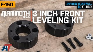
      Features & Specs

      • Three-Inch Front Leveling Kit
      • Corrects Factory Rake for a Level Stance
      • Increases Front Ground Clearance
      • CNC-Machined Aluminum Strut Spacers
      • Black Anodized Finish
      • Straight Forward, Bolt-on Installation
      • Fits 2004-2013 2WD/4WD Ford F-150 Models, Excludes Raptor

      Description

      Eliminates Factory Rake. A Mammoth Leveling Kit will raise the front of your 2004-2013 Ford F-150 by 3 inches to eliminate the original factory rake. This Mammoth Kit will not only level your F-150, but it will also increase the front end ground clearance as well.

      Quality Construction. These Mammoth Strut Spacers have been CNC-machined from aircraft grade billet aluminum for superior strength and durability. Mammoth then completes its Leveling Spacers in a durable, black anodized finish for good looks and long-lasting corrosion resistance.

      Straight Forward, Bolt-on Installation. Mammoth designed its Front Leveling Kit to be a straight forward, bolt-on install with no cutting or drilling required. With all the necessary hardware included, this Leveling Kit can be installed in about 2 hours time.

      Application. This Mammoth 3.0-inch Front Leveling Kit is specifically engineered to fit 2004-2013 2WD and 4WD Ford F-150 models. Does not fit SVT Raptor.

      Mammoth 4x4

      Shop All Truck Parts And Accessories

      Shop All Truck Leveling Kits

      Shop All Truck Lift Kits

      Fitment:

      Details

      Mammoth T542568

      CA Residents: WARNING: Cancer and Reproductive Harm - www.P65Warnings.ca.gov

      Installation & What's in the Box

      Installation Info

      What's in the Box

      • (2) 51.5mm Thick Spacers
      • (6) M10x1.50 Bolts
      • (6) M10 Lock Nuts
      4.7

      Customer Reviews (104)

        Questions & Answers

        10 More Questions

        Will It Fit My F-150

        • 3.5L V6 EcoBoost - 11, 12, 13
        • 3.7L V6 - 11, 12, 13
        • 4.2L V6 - 05, 06, 07, 08
        • 4.6L V8 - 04, 05, 06, 07, 08, 09, 10
        • 5.0L V8 - 11, 12, 13
        • 5.4L V8 - 04, 05, 06, 07, 08, 09, 10
        • 5.4L V8 Raptor - 10
        • 6.2L V8 - 11, 12, 13
        • 6.2L V8 Raptor - 10, 11, 12, 13

            Related F-150 Categories