FREE 1 to 3-Day Delivery on Orders $149+ Details
How to Install Rough Country 7 in. Suspension Lift Kit w/ Shocks on your Sierra
Installation Time
1 days
Tools Required
- Floor Jack /Jack Stands
- 8mm Allen Socket
- 10mm socket /wrench
- 11mm socket /wrench
- 13 mm socket/wrench
- 15mm socket / wrench
- 17mm socket/wrench
- 18mm socket /wrench
- 21mm socket /wrench
- 22mm socket /wrench
- 24mm socket /wrench
- 19mm socket /wrench
- 35mm socket
- 1/2” socket/wrench
- 9/16” socket /wrench
- #30 Torx bit
- Reciprocating Saw
- Drill
- 9/16” Drill Bit
- 3” Hole Saw
- Hand Grinder

Shop Parts in this Guide
FRONT INSTALLATION
1. Park the vehicle on a level surface and chock the rear wheels. Raise the hood and disconnect the battery using a 10mm socket. Lock the steering wheel in the straight position.
2. Jack up the front of the vehicle. Place jack stands under the frame rails and lower onto jack stands letting the front suspension hang.
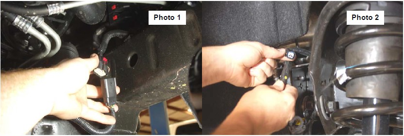
3. Remove the tires and wheels. Remove the 6 bolts holding the factory skid plate using a 15mm socket. Unplug the two connectors going to the electric power steering wiring harness behind the front skid plate. See Photo 1.
4. Remove and unplug the ABS sensor wire from the frame as shown in Photo 2.
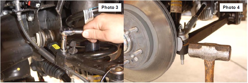
5. Remove the sensor wire from the plastic clip. Remove the brake line bracket from the control arm using a 10mm wrench. See Photo 3. Next remove the bracket line bracket from the control arm pocket with a 13mm wrench.
6. Using a 21mm wrench, remove the tie-rod nut as shown in Photo 2. Strike the front of the mount to dislodge the tie rod end. Remove from the knuckle.
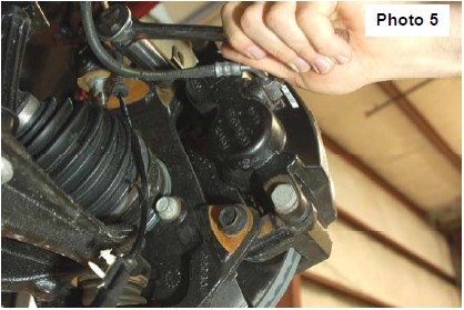
7. Remove the brake caliper using a 18mm socket. Hang the caliper out of the way and remove the rotor using a 30 torx socket. See Photo 5.
8. Use a 10mm socket to remove the brake line bracket from the knuckle.
9. Remove the dust cap and then remove the axle nut using a 35mm socket.
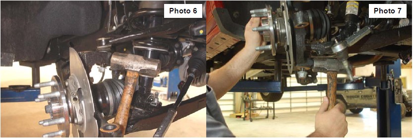
10. Remove the upper ball joint using a 18mm socket and separate using a hammer and striking the knuckle on the side as shown in Photo 6.
11. Remove the lower ball joint using a 24mm socket and separate with a hammer as shown in Photo 7. Next remove the knuckle from the truck.
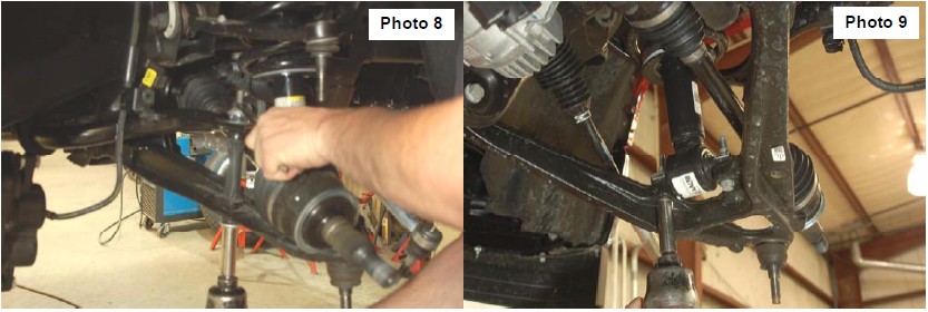
12. Using a 15mm wrench and socket remove the sway bar links from the truck. See Photo 8.
13. Remove the lower strut bolts using a 15mm socket as shown in Photo 9 and remove the upper strut nuts using a 18mm wrench. Remove the strut from the truck.
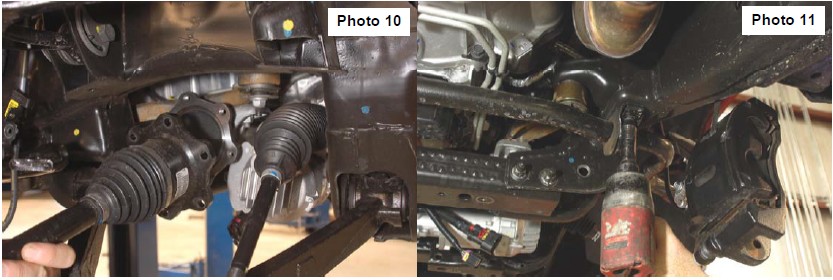
14. Remove CV axle bolts using a 15mm socket. See Photo 10.
15. Using a 10mm socket remove the sway bar from the bottom of the frame. See Photo 11.
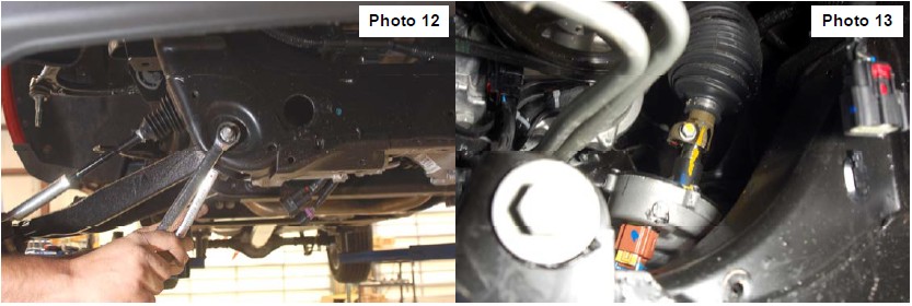
16. Remove the lower control arm using a 18mm wrench and a 24mm socket. See Photo 12.
17. Make sure the steering wheel is straight, mark the intermediate shaft and the rack and pinion as shown in Photo 13.
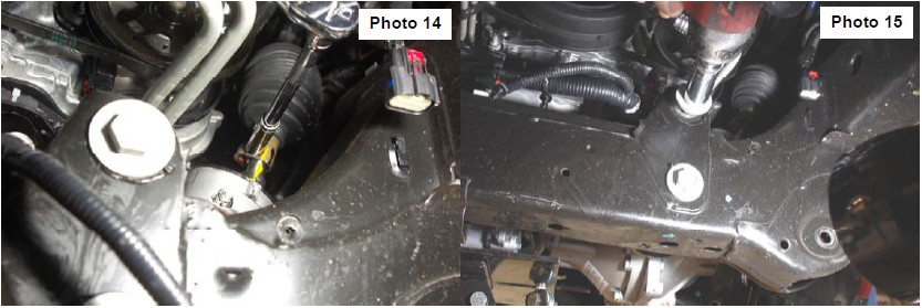
18. Using a 11mm socket, remove the bolt in the intermediate shaft. See Photo 14.
19. Support the rack and pinion with a jack and take good care not to hit or drop the rack. Use a 24mm socket and a 18mm socket to remove the bolts from the rack and pinion. Carefully lower rack and pinion down making sure no wires are in harms way. Place the rack and pinion in a safe secure area. See Photo 15.
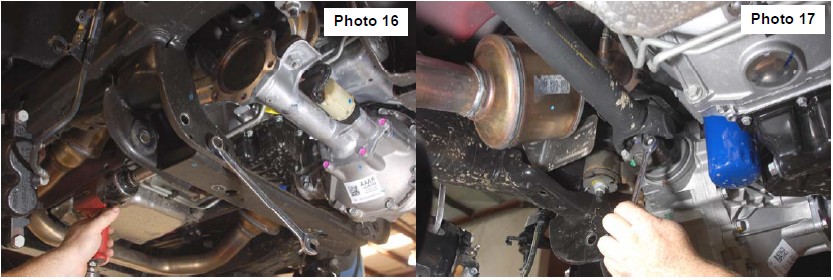
20. Using a 18mm wrench and socket remove the factory lower rear cross-member. See Photo 16.
21. Using a 11mm socket remove the driveshaft from the front diff . See Photo 17. Unplug the actuator wire from diff. remove wire loom from diff. remove vent tube from diff.
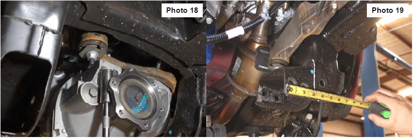
22. Support diff. Using a 18mm socket and 21mm socket remove the bolts from diff. lower diff from truck. See Photo 18.
23. Mark the front and rear sides of the driver’s side rear control arm pocket, measure 3 3/8” and cut rear lower control arm pocket. See Photo 19.
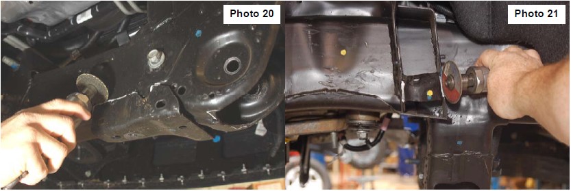
24. Cut and remove the skid plate bracket from the front factory cross-member. Cut the corners out of both front lower control arm pockets. See Photo 20.
25. Cut the upper control arm bump stop out as shown in Photo 21.
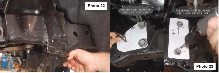
26. Then measure 1 5/8 from the cam bolt pin down and mark both side of the front control arm pocket this is your cut line. Cut straight back to frame then straight down against frame. Clean and paint all cut areas. See Photo 22.
27. Using template on passenger side of truck mark and drill the hole to a 9/16. this hole is for the rack and pinion mount. then on driver side using the template mark and cut the area using a 3 inch hole saw. See Photo 23.
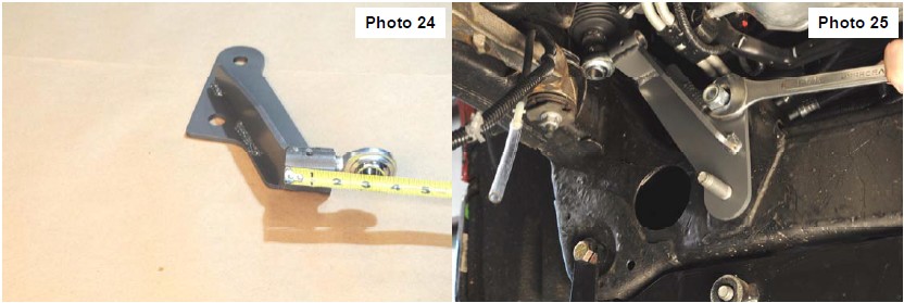
28. Install the hiems joint into the steering bracket and adjust the length to 3” from the back of the threaded tube to the center of the center of the ball. Use supplied set screw to lock the hiems into place. See Photo 24.
29. Install the 18mm x 150mm bolt, washer, and nut in the top mounting hole and factory bolt on lower hole. See Photo 25.
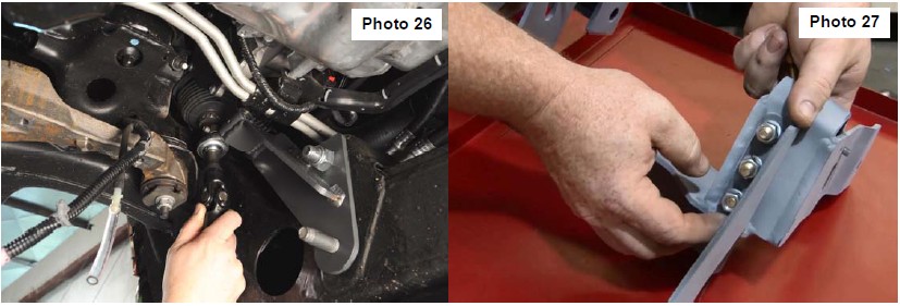
30. Install the steering extension through the 3/4 hiems and slide the stock steering shaft onto the steering extension. Lock into place using the factory bolt. See Photo 26.
31. Install the front upper control arm support brackets onto upper control arm drops brackets using 3/8” x 1.25” bolt, washers, lock washers, and nuts but do not tighten at this time. See Photo 27.
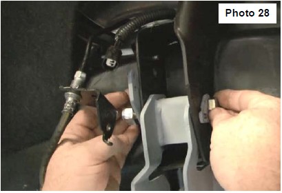
32. Install upper control arm drops onto truck using supplied 9/16” x 4” bolts and nuts using four cam lock washer per side with one cam lock washer with a tail on the back side for the ABS wire. See Photo 28.
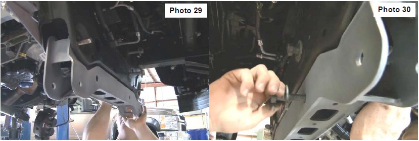
33. Install the front cross-member using the supplied 5/8” x 5.0” bolts, washers, nut. Bolt must be install from back to front. See Photo 29.
34. Install rack and pinion using stock bolts on driver side and one stock and one new on passenger side 12mm x 140mm bolt and washer. Slide steering extension onto rack and pinion steering stud as you are installing it. See Photo 30.
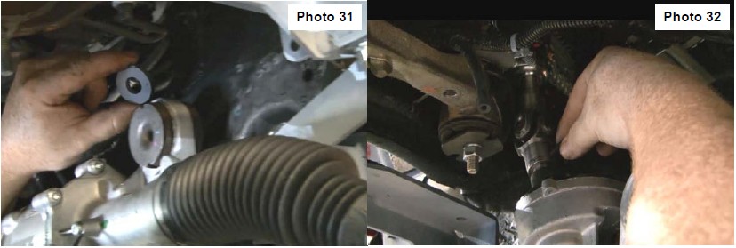
35. Install the rack and pinion spacer in-between the rack and pinion and frame on the passenger side top mounting hole. Install set screw into steering extension make sure set screw goes into groove on rack and pinion shaft. Use the 5/16” jam nut on the set screw using a 13mm to tighten. Using a 18mm,19mm socket and 24 mm socket tighten rack and pinion to frame. Plug in the two connectors for rack and pinion. Tighten the bolt that connects the steering shaft to the steering extension using a 11mm socket. See Photo 31 & 32.
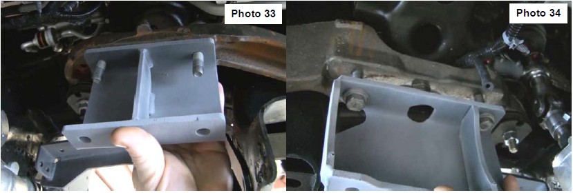
36. Install diff drop brackets using stock hardware on driver side and new supplied 12mm flange nut for passenger side. Use a 18mm socket or wrench to tighten. See Photo 33 & 34. Install diff vent extension tube into stock hose.
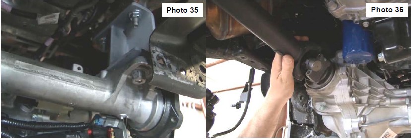
37. Install diff using new supplied 12mm x 45mm bolts and nuts. Be sure not to hit or push diff into rack and pinion. Use new bolts and nut on driver side and use new bolts with old stock nut on passenger side. Use a 18mm and 19mm socket and wrench for new bolts and a 21mm for the stock nuts. Plug in the 4x4 actuator and vent tube. See Photo 35.
38. Install driveshaft using stock hardware and a 11mm wrench to tighten. See Photo 36.
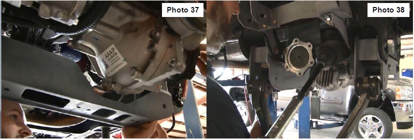
39. Install rear crossmember using new 5/8” x 5.5” bolts, washer, and nuts. Install bolts front to back of truck. See Photo 37
40. Install upper and lower control arms using stock bolts. See Photo 38. Then tighten all cross-member and upper control arm drop bolts. Use a 24mm wrench and socket on cross-member bolts. Use a 21mm and a 22mm wrench and socket on upper drops. Then use a 14mm wrench and socket to tighten all 3/8 bolts on upper control arm drop brackets.
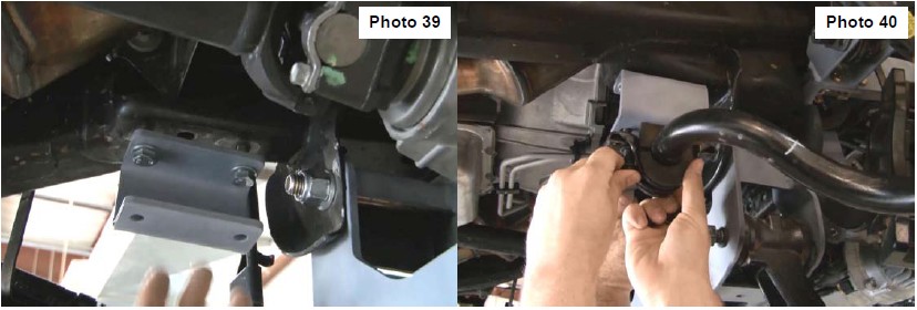
41. Install sway-bar drop bracket using 10mm x 35 mm bolts and washers. Tighten using 17mm wrench. See Photo 39. Install sway-bar using stock bolt with new 10mm nuts. See Photo 40. Use a 10mm socket and 17mm wrench to tighten. Install stock sway-bar link using a 15mm to tighten.
42.Install CV axle using stock hardware and a 15mm socket to tighten.
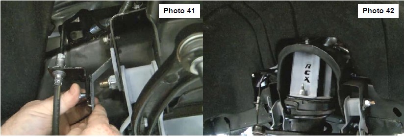
43.Install brake line bracket using the supplied 3/8” x 1” bolts, washers, and nuts. See Photo 41. Use a13mm wrench and socket to tighten.
44.Press in the10mm studs into the strut spacer. Install strut spacer on to strut using stock hardware and a 18mm wrench to tighten.
45.Install strut into truck using the supplied 10mm nuts and lock washers. Use a 17mm wrench to tighten. See Photo 42. Use stock hardware for lower strut mount and use a 15mm wrench to tighten lower strut bolts
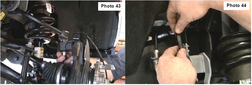
46.Install knuckles using stock hardware. See Photo 43. Use a 24mm for lower ball joint a 18mm for upper joint and a 35mm for axle nut. Install rotor and install bolt using a 30mm torx socket. Install the brake caliper using a 18mm socket for the bolts.
47.Install stock brake line bracket to upper control arm using a 10mm socket. Install ABS wire onto the cam lock washers and plug in. See Photo 44. Install tie-rod using a 21mm and 10mm to tighten.
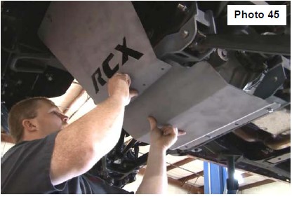
48.Install skid plates using supplied 3/8” x 1.25” bolts and washers. First insert the stock two bolts for upper skid plate and let the lower part hang. Install the bolts to the rear of the lower skid plate first then push the lower skid into place and overlap it with the front skid. The 3/8” bolts will go through both skids into the front crossmember. See Photo 45. Use a 14mm and a 15 mm socket to tighten all bolts
49.Jack up the truck and remove the jack stands. Lower truck on ground tighten upper and lower control arm bolts using 21mm for upper and 18mm and 24mm socket and wrench for bottom.
REAR INSTALLATION
1. Chock the front tires.
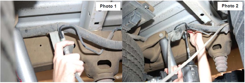
2. Before jacking up the rear of the vehicle. Remove the stock brake line bracket using a 13mm wrench, from the driver side frame rail to allow the extension bracket to be installed. Also remove the clip securing the hard line and wiring hardness to the top of the frame. See Photo 1. The stock bolts can be accessed from the side of the vehicle. Retain the stock hardware for reuse.
3. Install the brake line bracket to the new bracket with the supplied 5/16” x 3/4” bolts, nuts /washers. Reinstall the assembly in the stock location with the stock hardware using a 13mm wrench. See Photo 2.
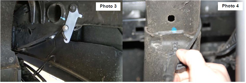
4. Remove the e-brake wire bracket from the frame with a 13mm socket. Use the supplied drop bracket and the factory bolt to mount to the frame. Use the supplied 5/16” x 1” bolt, washers, and nut to mount factory wire bracket to the new drop bracket as shown in See Photo 3.
5. Remove the ABS wire, if equipped, from the frame rail as shown in Photo 4 to allow slack in the line.
6. Jack up the rear of the vehicle and place jack stands under the frame rails. Remove tire and wheels.
7. Lightly support the differential with a floor jack .
8. Remove the stock shock absorbers using a 21mm wrench. Retain the hardware for reuse.
9. Remove the stock u-bolts and lower the axle to allow the supplied block to be installed. Discard the factory block if so equipped.
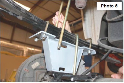
10. Install the new block with the supplied 7/16” X 3” u-bolts on the leaf spring. Do not tighten at this time. Jack up the axle to meet the new block and make sure the center pin is in the axle. Tighten 7/16” u-bolts. See Photo 5. Note short side of block goes towards front of vehicle.
11. Install the supplied u-bolts and tighten using a 22mm wrench and a crossing pattern. See Photo 5.
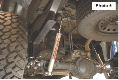
12. Install shock absorbers #658727 in the factory location tighten using a 21mm wrench. See Photo 6.
13. Using WD-40 lubricate the ABS wire and slide the rubber sleeve up to allow the wire to be reinstalled in the clip on the frame. The connector will not be reattached to the top of the frame. Reroute the lines as needed to gain sufficient slack.
14. Re-install tires and wheels.
15. Remove jack stands and lower vehicle to ground. 16. Place shock decals on shock absorbers and window decal on vehicle.
POST INSTALLATION INSTRUCTIONS
1. Check all fasteners for proper torque. Check to ensure for adequate clearance between all rotating, mobile, fixed, and heated members. Verify clearance between exhaust and brake lines, fuel lines, fuel tank, floor boards and wiring harness. Check steering gear for clearance. Test and inspect brake system.
2. Perform steering sweep to ensure front brake hoses have adequate slack and do not contact any rotating, mobile or heated members. Inspect rear brake hoses at full extension for adequate slack. Failure to perform hose check/ replacement may result in component failure.
3. On some vehicles the front lower skirting will need to be trimmed if using certain wheel /tire combinations and with heavy offset wheels. Trim only as needed.
4. Activate four wheel drive system and check front hubs for engagement.
5. Have a qualified alignment center align the vehicle immediately. Realign to factory specifications. The following are the recommended specifications:
Caster in degrees 4.5 -1.0
Camber in degrees 0.0—.3
Toe In in degrees 0.1 -.2
6. Perform head light check and adjustment to proper settings.
7. Check and retighten wheels at 50 miles and again at 500 miles.
8. All kit components must be retightened at 500 miles and then every three thousand miles after installation. Periodically check all hardware for tightness.
9. Install “Warning to Driver” decal on sun visor
Note: Installation of larger tires will require speedometer recalibration.