 FREE 1 to 3-Day Delivery on Orders $149+ Details
How to Install a Raxiom Auxiliary/Backup Light Kit on your Ford F-150
Installation Time
2 hours
Tools Required
- Vehicle Ramps and/or Jack Stands
- Flat head screwdriver
- Ratchet & Socket set OR
- Adjustable Wrench
- Small knife or Razor Blade
- Rotary tool (IE: Dremel) with
- cutting wheel and/or bit
Shop Parts in this Guide
Backup/ Auxiliary Lighting Wiring & Switch Kit
Parts List:
Wiring harness
PB-5051 Parts Bag
Tool List:
Vehicle Ramps and/or Jack Stands
Flat head screwdriver
Ratchet & Socket set OR
Adjustable Wrench
Small knife or Razor Blade
Rotary tool (IE: Dremel) with
cutting wheel and/or bit
Please familiarize yourself with the parts included as well as the instructions before attempting installation. Failure to read and follow the instructions below may result in personal injury or damage to property.
Installation of this product may not require use of vehicle ramps/ jack stands. If you require the use of devices that raise the vehicle off the ground and do not feel confident in driving the vehicle on and off ramps and/or placing it on jack stands, take this product to a professional for installation. Our company assumes no liability for misuse of devices that raise a vehicle off the ground. Serious injury or DEATH could result if safety precautions are not followed.
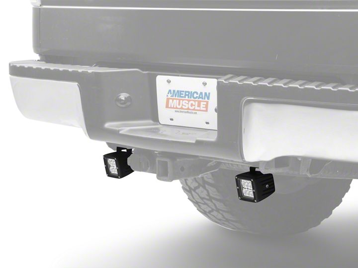
Because the placement of lamps and style of lamps vary so greatly, refer to mounting instructions that came with the lamps received from us. This manual details how to wire the vehicle for lamps only.
Wiring in Engine Bay:
1. Open hood of vehicle and make sure it is held open securely. Turn vehicle off and remove the key. Engage the emergency brake.
2. Familiarize yourself with the wiring harness included in the kit. On one end, there is a small black box (relay) with various wiring including a blue wire which will be mounted at the rear of the vehicle. On the other end there is a thick red and black wire -the red wire has an inline fuse holder (black rectangular box).
3. Open the cap on the fuse holder and remove the fuse. Sit off to the side for re-installation later.
4. Disconnect negative vehicle battery cable(s).
5. Attach the black ground cable to a negative (ground) in the engine compartment.
6. Connect the red wire to a positive ( 12 volt) power source in the engine compartment.
7. Route the switch wiring (red, blue, black wire bundle) into the passenger compartment (on drivers side). Normally these wires can be routed through an existing rubber grommet or boot.
8. If you are unable to find an existing spot you can pass the wiring through, you'll need to drill an 11/16 inch hole in the firewall. You MUST be sure that doing so will not interfere with any existing systems. You need to check to make sure you will not damage anything on the inside of the firewall. Drill the hole very slowly. Then insert the supplied rubber grommet. Note: You may find it easier to route the wiring through the grommet first, and then insert the grommet into the firewall.
9. Route the remainder of the wiring harness (relay, lamp extensions, etc.) to the rear of the vehicle. Caution should be exercised when mounting the wiring harness throughout this installation. You'll need to stay away from any significant sources of heat (like exhaust pipes) and any moving parts
(like suspension). It is best to follow existing bundles of wiring that run along the body of the vehicle.
10. Now that you have routed the wiring harness to the back of the vehicle, you'll want to find a place to mount the relay. The relay should be mounted so that the wiring is facing towards the ground. Run one of the supplied zip ties through the wiring of the relay and attach it to a nearby object.
11. Plug in the wiring harness lamp extensions to the lamps you have already installed on the vehicle.
12. Locate the blue wire on the wiring harness. This wire will be used to gain a signal from the reverse lights. If you would prefer for the lights to only come on with the cabin switch, coil the wire up and secure it out of the way. Skip to step 16.
13. Locate the blue wire on the wiring harness. This wire will be used to gain a signal from the reverse lights. It will plug into the blue wire-tap supplied in the parts bag. It can be connected to one of two places. If your vehicle was equipped from the factory with the tow package, connect it to the 7-pin connector. See vehicle owners' manual for the correct wire to tap into (connect to reverse signal). If your vehicle was not equipped from the factory with a tow package, you can also connect it to the 12v reverse bulb wire on your drivers' side tail light.
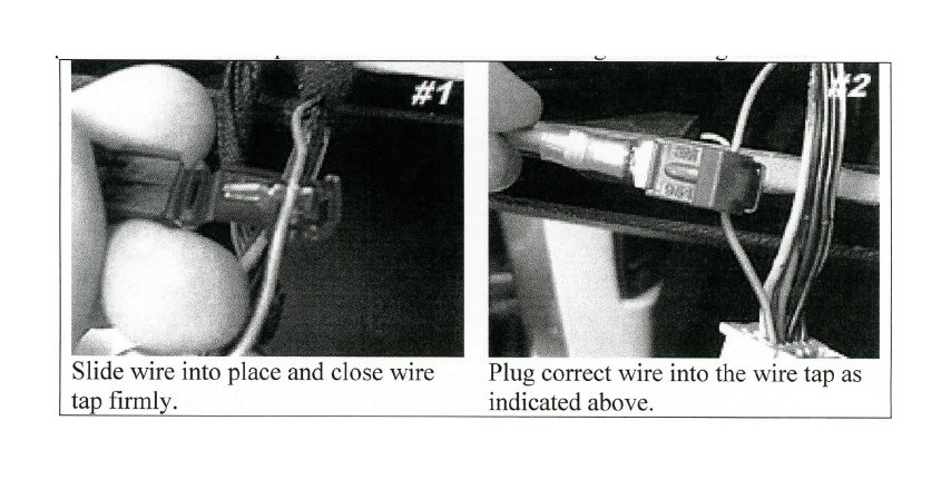
14. Locate the proper reverse signal wire you will need to connect to. Using the supplied blue wire tap, slide the wire onto the wire tap. See picture 1 below. The wire should sit in the middle of the two teeth. Squeeze down on the wire tap making sure it snaps closed. Do not cut Wire!
15. Plug the blue wire from the wiring harness into the back of the blue wire tap. See picture 2 below.
16. Finish securing all of the wiring located at the rear of the vehicle using the supplied zip ties. Remember - you need to make sure that none of the wiring harness comes in contact with any component that moves or produces heat as this will damage the wiring harness.
Installing switch in passenger compartment:
Decide where you want to mount the switch included with the kit. Some thought and examination should be put into this to find an appropriate spot. Keep in mind that you'll need to determine what is immediately behind the panel you are thinking of mounting the switch in. You can mount the switch anywhere you would like, just make sure your wiring will reach before mounting the switch (or you can plan to extend the wiring if necessary). Run through the check list below:
• Be sure wiring will reach the spot you wish to mount the switch, or plan on extending the wiring.
• Determine there is nothing immediately behind the location you wish to mount the switch.
• Make sure the spot you are mounting the switch is a flat surface.
• Be sure the panel you are mounting the switch in is not more than % inch thick (so that the switch locks into place properly).
• Before cutting, check and double check your alignment, placement, etc.
Cutting out the hole should be done carefully. The best thing to do is trace the switch outline on the panel. If possible, removal of the panel from the vehicle will make this MUCH easier than doing it in the vehicle. The panel surface should be flat. Using a rotary tool with a cutting wheel, cut well inside the trace marks. You're better off having to shave off extra bits of plastic to achieve the right fit than making the hole too big. You might find you have to make adjustments 5-10 times to get the perfect fit - that's okay, patience is key! After you have mounted the switch, follow instructions below to connect the switch to wiring.
After the switch has been mounted, you'll want to decide how you would like the switch to operate. You have two options: Option 1 is for both the upper and lower light on the switch to illuminate when you turn the switch to the ON position. Option 2 is for the lower light on the switch to illuminate when you turn the switch to the ON position. The upper light on the switch will come on and off with your vehicles dash lights. Option 2 requires advanced knowledge to connect properly and because vehicle electrical configurations vary so widely, we are unable to offer technical support for this particular function.
Option 1 (normal connection):
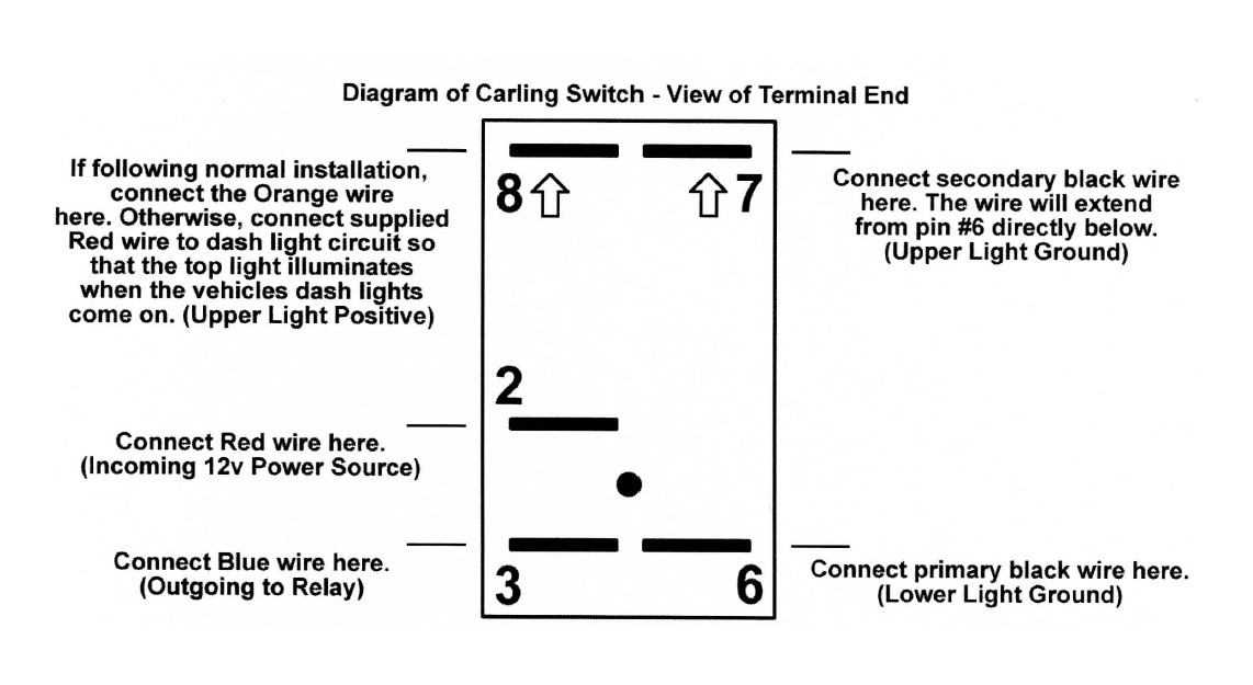
1. Plug the wiring from the harness into the back of the switch as follows (see diagram below for additional assistance): Primary black wire (larger gauge wire) plugs into Pin#6. Secondary black wire (smaller gauge wire) plugs into Pin#7. Red wire plugs into Pin#2. Blue wire plugs into Pin#3. Orange wire (which is connected to the Blue wire) plugs into Pin#8.
2. Secure all wiring under the dash with zip ties. Be sure the wiring will not affect operation of the brake pedal. Failure to secure the wiring under the dash could cause an ACCIDENT.
Option 2 (advanced connection):
1. Note: Because of the complexity of vehicle electrical systems, we only recommend advanced users configure the product this way. CAN bus systems are easily damaged if proper precautions are not exercised. Plug the wiring from the harness into the back of the switch as follows (see diagram below for additional assistance): Primary black wire (larger gauge wire) plugs into Pin#6. Secondary black wire (smaller gauge wire) plugs into Pin#7. Red wire plugs into Pin#2. Blue wire plugs into Pin#3. Orange wire should be zip tied to body of wiring so it does not make contact with switch. Supplied red wire (about 18 inches long) plugs into Pin#8.
2. Opposite end of the short Red wire you connected to Pin#8 should tap into a factory 12v positive power source that is only powered when the dash lights are illuminated. If you find that the upper light is remaining on all the time, you will need to find another place to connect it that is only powered with 12volts when the dash lights (for night time driving) are on.
3. Secure all wiring under the dash with zip ties. Be sure the wiring will not affect operation of the brake pedal. Failure to secure the wiring under the dash could cause an ACCIDENT.
Final Installation:
1. Re-install the blue fuse you pulled out the of fuse holder at the beginning of the installation.
2. Re-connect the negative battery cable to the truck battery(s). Remember to re-tighten the bolt.
3. Double check everything to make sure it was connected properly. Test the switch to make sure the lights turn ON and OFF. Also check to make sure that the lights come on when the vehicle is placed in reverse (if you decided to connect it this way). If any issues exist, visit the trouble shooting guide below. Otherwise proceed to the next step.
4. Review all of the wiring that you installed on the vehicle. Be sure that none of it will be exposed to extreme heat or get in the way of moving parts. Be sure to trim the excess tail of all zip ties if desired.
5. Enjoy your new reverse/ work lighting! Remember - because the wiring system is designed to operate independently from the vehicle, the lights will remain on after you turn the vehicle off. Be sure to always turn the switch into the OFF position when the lighting is not in use. If you leave your lights on for too long, you may drain your battery. Note: It is illegal to turn these lights on while moving forward on public roads. Depending on the brightness and intensity of the lights you installed, the light could blind people behind you. Always remember to turn the lights off before you begin moving. Failure to do so could cause injury and you could receive a citation from law enforcement.
Trouble shooting guide: Lights won't turn on at all -
• Check the ground cable you connected under the "Wiring in engine bay" section. Make sure that it is making proper contact and that the bolt is tightened.
• Check the ring terminal you connected to 12v power. Make sure that it is making proper contact and that the bolt is tightened.
• Check the blue fuse installed in the fuse holder (small black box located on red wire in the engine bay). Make sure it is plugged in completely and has not been blown (On a blown fuse the filament in the middle of the two posts has been broken).
Lights do not turn on when vehicle is placed in reverse but do work with the switch -
• Check to make sure the blue wire was connected to a reverse signal as instructed above.
• Check to make sure you installed the wire tap on the proper reverse wire as indicated above. Also make sure the wire tap cover is closed completely.
Switch does not work or does not illuminate -
• Check to make sure you connected the wiring to the switch properly. The diagram included above is helpful and insures that you connect the wiring to the switch properly.
When the lights are activated I hear a "click" toward the rear of the vehicle -
• This is normal. The relay clicks when the lights turn on and off.
If you are still having trouble with your product, please contact us for technical assistance.

