FREE 1 to 3-Day Delivery on Orders $149+ Details
How to Install Raptor Series 5 in. Cab Length Oval Tube Side Steps - Stainless on your F-150
Installation Time
2 hours
Tools Required
- RATCHET
- TORQUE WRENCH
- 17MM SOCKET
- 6MM HEX BIT

Shop Parts in this Guide
Raptor Series Warranty
LIMITED TEN (10) YEAR WARRANTY
For Powder Coated Steel Products
CYC Engineering, Inc. guarantees the original purchaser of our products a limited ten (10) year warranty from the date of original purchase against manufacturer defects in materials, workmanship and finish under normal use. The step pads are covered under warranty for 1 year. This warranty does not include damage resulting from road hazards such as gravel or other debris, product misuse, improper installation, impair-ments from accidents, product modifications, product neglect or scratches during the life of the product. This limited ten year warranty applies only to new products and is limited to the repair or replacement of company's products. Warranty does not include costs of removal, installation, labor, inconvenience or consequential damages. Original purchaser must return defective merchandise along with the purchase receipt, to the original place of purchase.
LIMITED LIFETIME WARRANTY
For Stainless Steel Products
CYC Engineering, Inc. guarantees the original purchaser of our products a limited lifetime warranty from the date of original purchase against manufacturer defects in materials, workmanship and finish under normal use. The step pads are covered under warranty for 1 year. This warranty does not include damage resulting from road hazards such as gravel or other debris, product misuse, improper installation, impairments from accidents, product modifications, product neglect or scratches during the life of the product. This limited lifetime warranty applies only to new products and is limited to the repair or replacement of company's prod-ucts. Warranty does not include costs of removal, installation, labor, inconvenience or consequential damages. Original purchaser must return defective merchandise along with the purchase receipt, to the original place of purchase.
Torque Specifications:
For Frame Mount Installations
Frame mount bolts are torqued to 70 Ft Lbs. All other M8 through M12 sized bolts/nuts are set to 15-20 ft lbs.
Note: When installing the brackets and bars, all hardware must be left loose until all the items are attached.
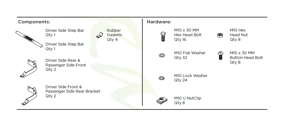
1. Remove all contents from the package and check stainless steel tubes for any damage. Also, verify that all components and hardware listed above are included before you begin installation.
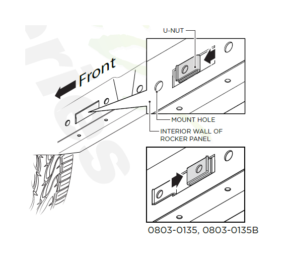
2. Remove the black tape and large rubber grommets over the mounting holes located on the inside face of the rocker panel.
3. Existing mounting holes are located on the interior wall of the rocker panel. These mounting holes will be used per the following instruction.
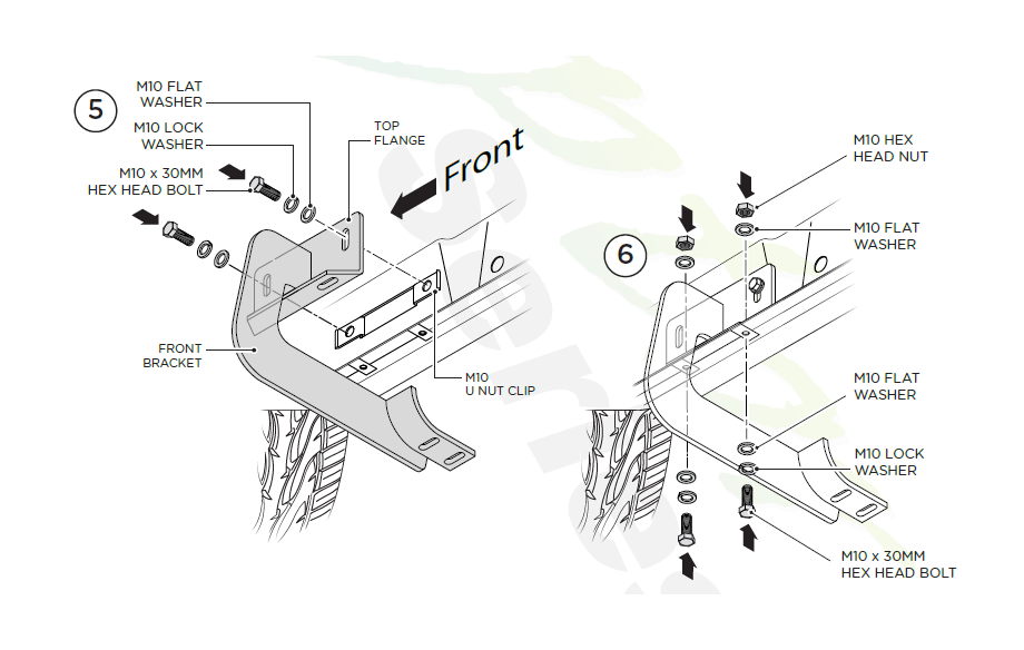
On the vertical wall of each rocker panel, install the U-Nut Clips as shown for both front and rear brackets for the top hole positions of only. Install these U-Nut Clips so that the threads are to the inside of the rocker panel. Be careful not to drop the U-Nut Clip inside of the rocker panel.
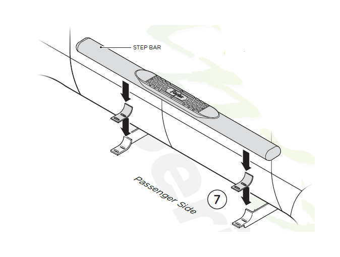
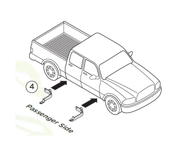
4. On the passenger side of the Rev 1-0814 vehicle, align Front and Rear brackets as shown.
5. Install the Top Flange of the passenger side Front Bracket by fastening two (2) M10 x 30MM Hex Head Bolts, two (2) M10 Flat Washers and two (2) M10 Lock Washers into M10 U Nut Clips.
6. Complete the installation of the Front Bracket by using two (2) M10 Hex Head Nuts, four (4) M10 Flat Washers and two (2) M10 Flat Washers. Repeat this process for the Rear Bracket. Hand tighten all hardware.
Note: Rear Bracket is 1/2" longer than Front Bracket.
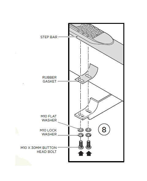
7. Plate the Step Bar and Rubber Gaskets onto the Brackets. Each Step Bar is marked Driver and Passenger.
8. Install the Step Bar onto each Bracket using two (2) M10 X 30MM Button Head Bolts, two (2) M10 Lock Washers and two (2) M10 Flat Washers.
Tighten until the split lock washer is flat against bracket and snug. DO NOT over tighten and strip the threaded insert in the tube.
Repeat these steps for driver side installation. When all hardware is in place, everything must be tightened. See Page 1 for Torque Specifications.