FREE 1 to 3-Day Delivery on Orders $149+ Details
How to Install Putco Bar Design Lower Bumper Grille Insert w/ 10 in. Luminix Light Bar & Heater Plug Opening - Black (15-17 All, Excluding Raptor) on your Ford F-150
Tools Required
- Pliers
- Flat Head & Philips Screwdriver
- Rubber Mallet
- 7/16" Wrench
- 7/16" wrench
- 3/4 " Drill Bit
- Drill
- File

Shop Parts in this Guide
Please read all instructions before installation and to check to see that all parts are included.
Bumper Grille Installation
Attention: Truck needs to be washed with soap and water in taped areas. Tape needs to be installed in temperatures above 18°C (64°F) and allowed 24 hours to fully set.
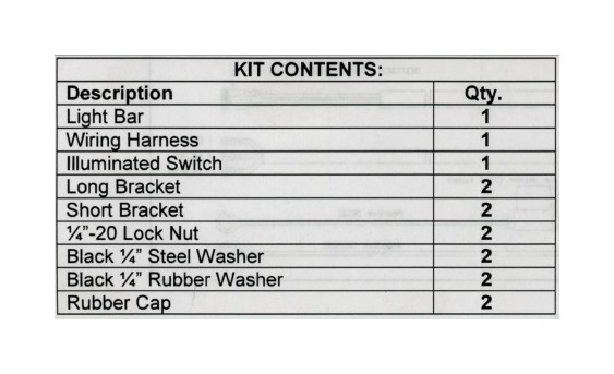
1 Remove bumper grille from packaging. Check to see if all parts from above table are included.
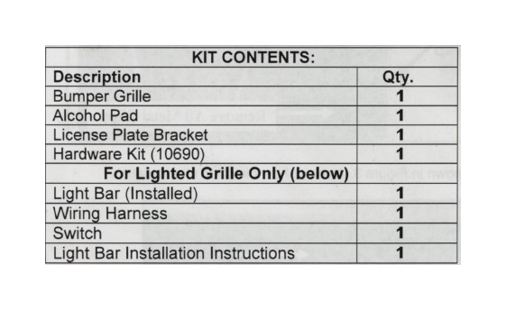
2. Remove factory plastic front license plate bracket, if truck has front license plate. Flex bracket untill both sets of clips release. Inner clips may need to be released with flat head screwdriver Refer to Figure 1
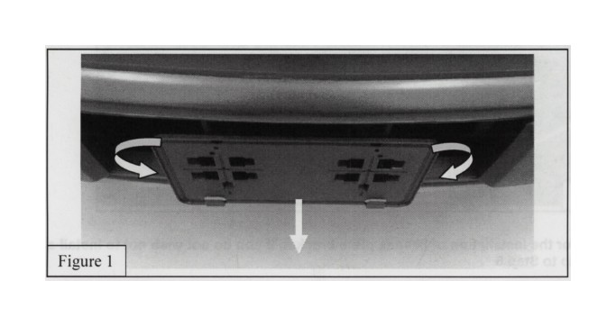
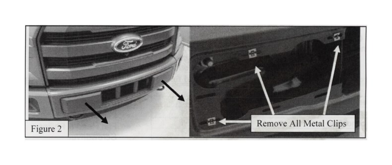
Remove factory front plastic bumper trim from bumper Pull or pry off trim with a flat head screwdriver Verify that all metal clips are removed with bumper trim. If not, remove the remaining ones with piers or flat head screwdriver Refer to Figure 2
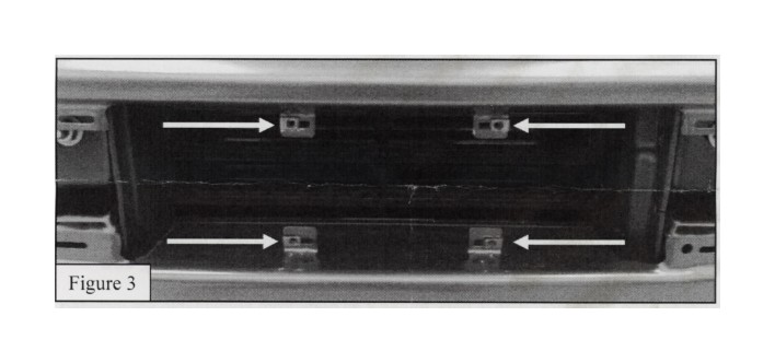
3. Insert supplied clip nuts in locations shown in Figure 3. Arrows show direction of installation.
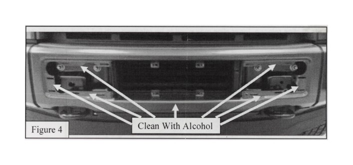
4. Use alcohol pad the clean locations shown in Figure 4
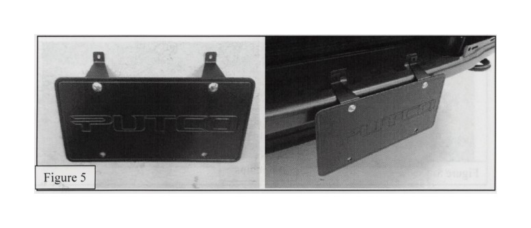
Note: Step 5 is for the installation of license plate bracket. If you do not wish not to install a license plate skip to Step 6
5. (OPTIONAL STEP) Mount license plate onto provided license plate bracket as shown in Figure 5. Use supplied 1/4"-20 hardware. Tighten with 7/16" wrench and Philips screwdriver (Tape on bracket goes toward bottom of license plate) Once mounted remove backing on tape and stick in location shown in Figure 5 (Verify holes in bracket line up with lower clips nuts installed in Step 3)
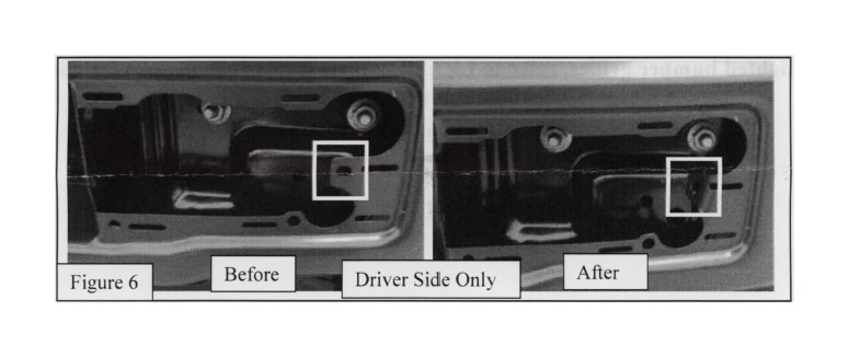
6. Use rubber mallet to bend tab shown in Figure 6 back far enough to clear grille insert.
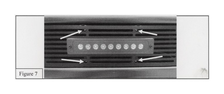
7 Remove tape backing on the back side of the grille. Place center of grille up to the bumper making sure the tape does not stick to the bumper yet. Mount center of grille using the supplied #8 bolts, washers and clip nuts (previously installed in Step 3). Refer to Figure 7. Tighten using supplied hex wrench. For lighted grilles (Verify your wire is in a location easily accessible to plug in wire harness)
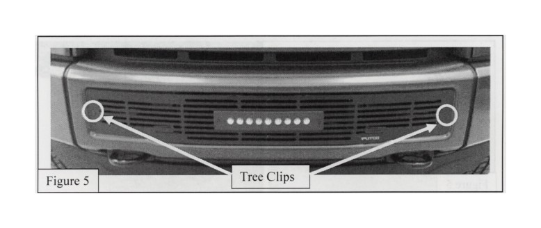
8. Use supplied plastic tree clips to secure ends of bumper grille to the truck (Figure 8). Push grille against bumper and hold for 30sec. This will set the tape.
For lighted bumper grilles, refer to Light Bar Installation Instructions for wiring installation instructions.
Please read all instructions before installation and to check to see that all parts are included.
Light Bar Installation
1 Remove light bar from packaging. Check to see if all parts from above table are included.
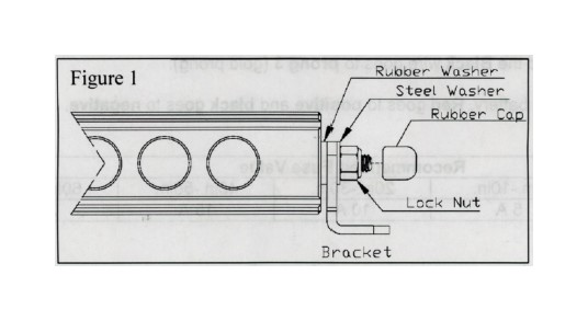
2. Remove rubber cap, lock nut, and steel washer from light bar Leave rubber washer on, this will go between light bar and bracket.
3. Place selected brackets onto light bar, reinstall hardware as shown in (Figure 1). Tighten nut with 7/16" wrench.
4. Place light bar and mark bracket holes in desired location. Remove light bar and drill holes to the size required for your chosen mounting hardware.
5. Mount light bar with chosen hardware in your desired location.
Wiring Installation
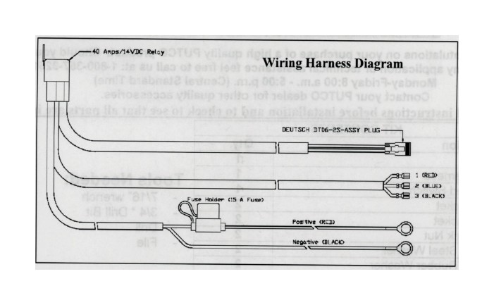
1 Remove wiring harness and switch from kit.
2. Route wiring harness so that the red and black power cables are routed to the battery, the three switch wires are routed to your desired switch location. and the Deutsch plug is routed to the light bar Keep wiring away from anything that will get hot.
3. Mount relay with desired hardware in a position under hood or in cab that is limited to water exposure.
4. Plug male (on the wiring harness) and female (on light bar) Deutsch plug connectors together
5. Drill 3/4" hole in desired switch mounting location. Verify there will be enough clearance behind switch to plug in the wires. Notch a small slit in the side of the hole using a file. This will keep the switch from turning.
6. Press switch into hole; verify that the notch made in step 5 lines up with the notch on the switch.
7 Plug wires into switch. Prongs on switch will be marked 1 through 3. Red wire goes to prong 1. Blue wire goes to Prong 2. and the Black wire goes to prong 3 (gold prong).
8. Attach power cable to the battery Red goes to positive and black goes to negative .