 FREE 1 to 3-Day Delivery on Orders $149+ Details
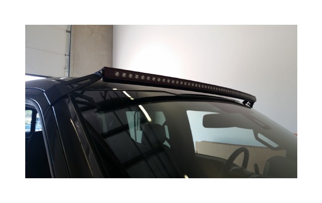
How to Install Putco 50 in. Luminix EDGE High Power Curved LED Light Bar Roof Mounting Brackets (15-17 All) on your Ford F-150

Shop Parts in this Guide
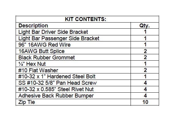
Please read all instructions before installation and to check to see that all parts are included.
Recommend installing 10050W Wind Noise Canceling Molding on 50" Light Bar before installing
Mounting Bracket Installation
1. Remove bracket kit from packaging. Check to see if all parts from above kit contents table are included.
2. Remove driver pillar trim, from inside cab, by pulling straight out. If pillar trim has handle, use 10mm socket to remove two bolts before pulling trim off.
3. Remove driver sun visor from inside cab. Use 7mm socket to remove the 2 bolts holding the visor to the roof.
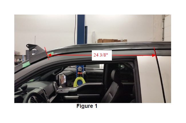
4. Place tape where bracket will be mounted. See Figure 1 for bracket location and distance. Place 2 rubber adhesive back bumpers to the body of the truck to prevent the bracket from being mounted too close to the paint and to prevent the bracket from damaging the paint while installed. Place the bracket on the door sill making sure the bracket is sitting on the flat surface in the door jam and up against the rubber bumpers. Using the bracket as a template, center punch each hole.
5. Drill 19/64” hole for rivet nuts to be inserted into. If holes are bigger then 19/64”, the rivet nut will not install correctly. (Recommend using new high quality hardened drill bits and starting with a 1/8” bit followed by a 1/4” bit and finally a 19/64” drill bit to drill holes)
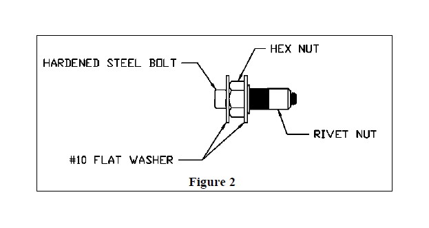
6. Place a #10 flat washer, hex nut, another #10 flat washer and rivet nut on black hardened steel bolt, shown in Figure 2, and place in drilled hole. Use a 7/16” wrench to hold hex nut and 5/32” hex bit to turn the hardened steel bolt until rivet nut is tightened down. (Do not install with drill, use hand tools only). Remove hardened steel bolt, flat washers and hex nut. Repeat in all four holes.
7. Mount brackets with pan head screws. Use 1/8” hex bit to tighten down screws. (Recommend sealing rivet nut areas with RTV Silicone and using thread locker for bracket screws)
8. Mount 50” light bar between brackets. Refer to light bar instruction for installation.
Wiring Installation
1. On the wiring harness, remove black plastic sleeve covering the red and black power wires between the relay and the fuse holder.
2. Cut red power cable behind fuse holder, be sure to leave enough wire to wire this piece back into the harness.
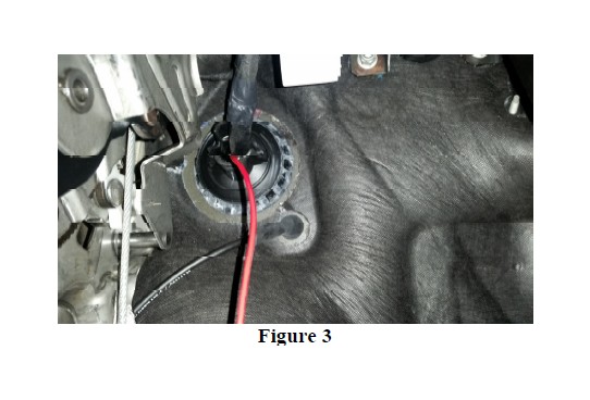
3. Insert the red power cable through the grommet pictured in Figure 3 located under the dash on the Driver's side. Leave the rest of the wiring harness by foot pedals in cab of truck for now. Bring red power cable up into engine bay.
4. Route red power wire to battery. Strip red power wire on harness and add the supplied red wire from kit using butt splice, trim other end to length. Strip and add back on red power wire and fuse holder (cut off in step 2) to other end of wire using the supplied butt splice. (Recommend using electrical tape to tape around butt splices after being installed)
5. Remove dash panel under steering wheel, by pulling straight out on the panel. Panel will unclip from the truck and hinge, resting on the floor.
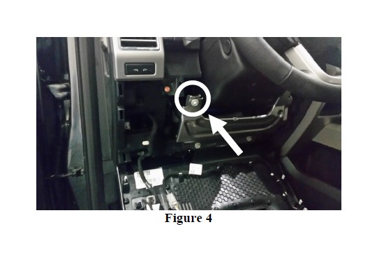
6. Attach black ground wire to location shown in Figure 4.
7. Run Deutsch connector (on wiring harness) up through the dash and out by the driver side A pillar.
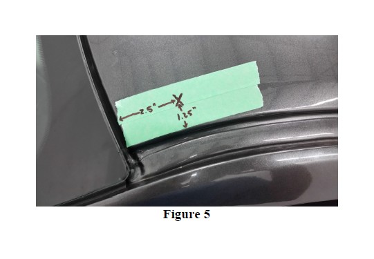
8. Drill 3/8” hole through roof. See Figure 5 for recommended location. (2.5 inches from the windshield and 1.25 inches from the water track) Insert grommet into hole. (Recommend sealing grommet areas with RTV Silicone after wiring is installed and verified)
9. To get wire through roof, one of the Deutsch connectors will need to be depinned so the wiring can run through the grommet, depending on where you would like the Deutsch connector to plug in at. To de-pin Deutsch connector, remove green or orange plastic end clip and use small flat screwdriver to unclip pins while pulling gently on wiring. When reassembling, verify corresponding wires match opposite Deutsch connector before repining. (Other option is to cut Deutsch connects off and butt splice corresponding wires together)
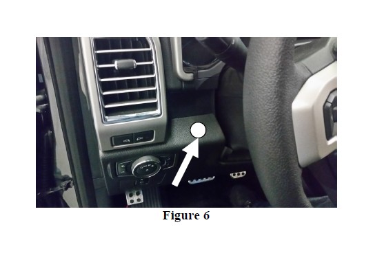
10. Drill ¾” hole and notch (as explained in light bar instructions) in desired location for the supplied switch. Recommended location is on lower dash panel by steering wheel. (Refer to Figure 6 for location)
11. Attach wire to switch and install as stated in the light bar instructions.
12. Attach red positive wire to battery; verify that the light bar turns on.
13. Mount relay, use zip ties to secure wiring.
14. Reassemble inside and outside of truck, ENJOY!!!!

