FREE 1 to 3-Day Delivery on Orders $149+ Details
ProRYDE 1.5 in. to 2.25 in. Adjustable Front Leveling Kit (09-16 All)
ALWAYS WEAR PROPER EYE PROTECTION & USE TOOLS SPECIFIC TO THE JOB! THIS PRODUCT HAS BEEN FACTORY PRE-TREATED WITH MARINE GRADE ANTI-SEIZE COMPOUND. NO LUBRICATION OF THE LARGE ADJUSTER THREADS IS NECESSARY PRIOR TO INSTALLATION.
STEP 1: On a flat, level surface, MEASURE preinstallation ride height, FRONT & REAR, and write down measurements.
Front (L)____________
Front (R)____________
Rear (L)_____________
Rear (R)_____________
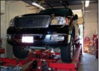
STEP 2: Position vehicle on a stable, flat surface or automotive lift. Suspend front wheels, lifting by the frame. Secure with jack stands & wheel chocks. Be sure engine is turned OFF and vehicle is in PARK.
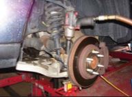
STEP 3: Support lower control arm & spindle assemblies, then remove front wheels.
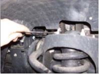
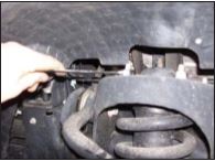
STEP 4: Disconnect ABS/ vacuum line brackets , if equipped, to allow slack.
STEP 5: Disconnect sway bar links at the lower control arm.
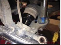
STEP 6: Loosen, but don’t completely remove, upper ball joint & outer tie rod nuts.
STEP 7: With stud nuts still installed, separate upper ball joints & outer tie rods from their tapers.
STEP 8: On 4WD models, separating the axle shaft from the spindle will simplify removal/ reinstallation of the strut. Be sure brake lines have adequate slack, and to properly support caliper & rotor.
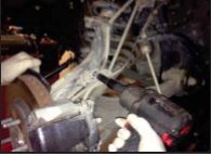
STEP 9: Disconnect & remove lower strut mounting bolts. Then completely remove upper ball joint & outer tie rod nuts separated from their tapers in step 7.
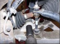
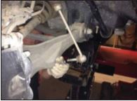
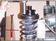
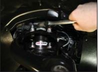
STEP 10: Supporting the strut assembly, remove the three upper strut mounting fasteners.
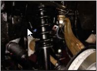
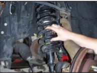
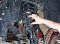
STEP 11: Remove the OE strut assembly
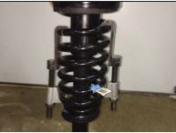
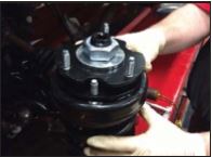
STEP 12: Secure new LIFTmachine kit to the strut assembly, using the OEM fasteners removed in Step 10. Be sure the Threaded Adjustment Screw Rotates FREELY after securing kit to the OEM strut.
STEP 13: 2014 F150 OPTION #1 Professional Method Skip this step for model years 2004-2013. Using professional tools, compress spring enough to rotate TOP STRUT MOUNT 180 degrees from its original position.
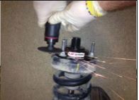
STEP 14: 2014 F150 OPTION #2 Do-it-yourself Method Skip this step for model years 2004-2013. Trim OE studs flush with top of each OEM nut.
STEP 15: IMPORTANT! Be sure the Threaded Adjustment Screw Rotates FREELY after securing kit to the OEM strut. If not, slightly loosen the three upper stud nuts and reposition the Threaded Adjustment Screw slightly UPWARD. Re-torque upper stud nuts to manufacturer’s specifications and recheck that the Threaded Adjustment Screw now rotates properly for adjustment after installation.
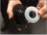
STEP 16: Install ONE tear-resistent Nylon Bearing to top of each inner adjustment screw, as shown, prior to installing each Top Connection Plate.
STEP 17: Install Top Connection Plate. Then, install Silver Top Connection Plate Spacer, Large 1-1/4”-12 Jam Nut (finger-tight only) & snap ring, in this sequence.
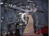
STEP 18: Reinstall strut assembly. The Threaded Inner Adjustment Screw should be threaded down in the most compact position for easiest reinstallation. HINT: The use of a pry bar against the lower control arm will help in the reinstallation of the strut assembly. NOTE: 2004-2013 struts with ONE lower mounting bolt will be reinstalled 180 degrees from the originally installed position.
STEP 19: Using new M10-1.5 nylok nuts, supplied, secure new Top Connection Plate to the OE strut tower, and torque to manufacturer’s specs. Then reinstall lower strut bolt (s) and torque to manufacturer’s specs.
STEP 20: Reconnect upper ball joint nut & outer tie rod nuts. HINT: The use of a bottle jack will assist in the reassembly of the ball joint to the knuckle. Reconnect sway bar link to the lower control arm. BE SURE TO CHECK YOUR WORK, and that all fasteners have been properly torqued to manufacturer’s specs.
STEP 21: Reconnect ABS/Vacuum line brackets, if disconnected in Step 4.
STEP 22: Reinstall tire/ wheel assemblies, and check that ALL suspension components and lug nuts have been properly torqued to manufacturer’s specs.
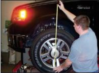
STEP 23: Lower the vehicle, jounce suspension and measure ride height of EACH SIDE of the vehicle. Measure from the bottom of the wheel/rim to the lip of the fender.
STEP 24: IMPORTANT! ADJUSTING FRONT RIDE HEIGHT AFTER INSTALLATION. 1) Lift vehicle by the frame, allowing wheels to hang freely. Secure using jack stands & wheel chocks. 2) Loosen the Large 1-1/4”-12 Top Jam Nut several complete turns. 3) Using a standard ½” ratchet, engage the ½” Threaded Adjuster at the TOP of the new lift kit. 4) Turn Counter-Clockwise to INCREASE ride height, and Clockwise to DECREASE ride height. 5) Each full turn of the Threaded Adjuster will result in approximately ¼” of ride height change. 6) Each ½ turn of the Threaded Adjuster will result in approximately 1/8” of ride height change. LOWER THE VEHICLE, JOUNCE SUSPENSION, AND MEASURE RIDE HEIGHT. BE SURE VEHICLE IS LEVEL FROM SIDE-TO-SIDE AND AT THE DESIRED RIDE HEIGHT, MAKING ADDITIONAL ADJUSTMENTS AS REQUIRED. RETORQUE ALL FASTENERS TO OEM SPECS. IMPORTANT! RETIGHTEN THE LARGE 1-1/4”-12 TOP JAM NUT AFTER FINAL ADJUSTMENTS ARE MADE.
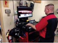
STEP 25: Perform a complete wheel alignment, utilizing a Certified Alignment Technician with experience working on lifted vehicles