 FREE 1 to 3-Day Delivery on Orders $149+ Details
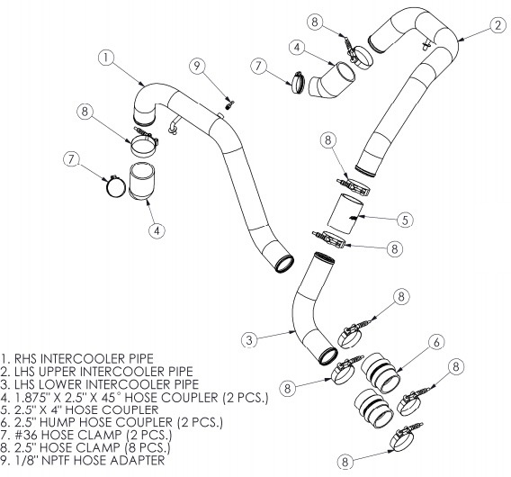
How to Install MBRP 2.5 in. Intercooler Pipe Kit, Hot Side on your F-150
Step 1: Remove the engine cover.
Step 2: Remove the “Y” section of the air intake by loosening the hose clamps from the rubber connections.
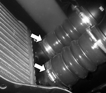
Step 3: Loosen the hose clamps and remove the hose couplers from both intercooler inlets.
Step 4: Remove the vacuum line from the passenger-side (RHS) stock intercooler pipe.
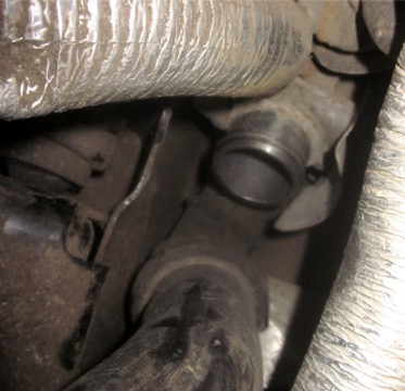
Step 5: From the passenger-side wheel well, loosen the hose clamp securing the passenger-side (RHS) intercooler pipe to the turbo. Remove the pipe from the vehicle.
Step 6: From the driver-side wheel well, loosen the hose clamp securing the driver-side (LHS) intercooler pipe to the turbo. Remove the pipe from the vehicle.
Step 7: Install a 1.875” X 2.5” X 45o Hose Coupler onto the driver-side turbo outlet using a #36 Hose Clamp. Do not tighten the clamp yet.
Step 8: Insert the LHS Upper Intercooler Pipe into the 1.875” X 2.5” X 45o Hose Coupler, securing it loosely using a 2.5” Hose Clamp.
Step 9: Position the LHS Upper Intercooler Pipe as necessary to insert the support post into the OEM rubber grommet.
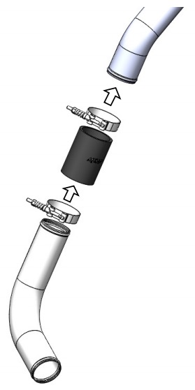
Step 10: Install the 2.5” X 4” Hose Coupler onto the bottom end of the LHS Upper Intercooler Pipe, securing it using a 2.5” Hose Clamp.
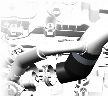
Step 11: Install one of the 2.5” Hump Hose Couplers onto the bottom inlet of the intercooler, securing it using a 2.5” Hose Clamp.
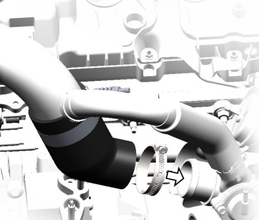
Step 12: Insert the shorter end of the LHS Lower Intercooler Pipe into the 2.5” Hump Hose Coupler with a 2.5” Hose Clamp, and the longer end into the 2.5” X 4” Hose Coupler with another 2.5” Hose Clamp (Refer to Figure 4). Do not fully tighten the clamps yet.
Step 13: Install a 1.875” X 2.5” X 45o Hose Coupler onto the passengerside turbo outlet using a #36 Hose Clamp. Do not tighten the clamp yet.
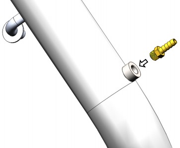
Step 14: Wrap the threads of the 1/8” NPTF HOSE ADAPTOR with Teflon tape and install it into the threaded bung on the RHS Intercooler Pipe.
Step 15: Insert the RHS Intercooler Pipe into the 1.875” X 2.5” X 45o Hose Coupler, securing it loosely using a 2.5” Hose Clamp.
Step 16: Install the other 2.5” Hump Hose Coupler onto the upper inlet of the intercooler, securing it using a 2.5” Hose Clamp.
Step 17: Position the RHS Intercooler Pipe as necessary to insert the support post into the OEM rubber grommet, then insert the bottom end into the 2.5” Hump Hose Coupler, securing it loosely.
Step 18: Install the previously-removed vacuum line onto the 1/8” NPTF HOSE ADAPTOR.
Step 19: Position the LHS and RHS Intercooler Pipes to obtain the best fit and maximize clearances, and then fully tighten all clamps.
Step 20: Replace the “Y” from the air intake and the engine cover. Trim the engine cover as needed to provide clearance to the LHS and RHS Intercooler Pipes.
Step 21: Verify that there is adequate clearance around all hoses, wiring, covers, etc. If not, relocate or adjust.

