 FREE 1 to 3-Day Delivery on Orders $149+ Details
How to Install K&N Series 77 High Flow Performance Cold Air Intake on your F-150

Shop Parts in this Guide
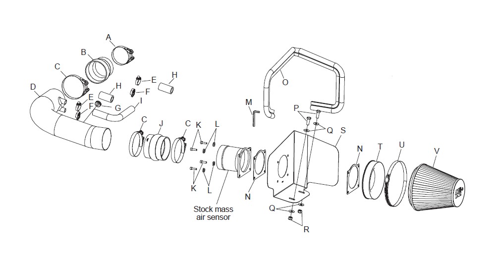
PARTS LIST:
NOTE: FAILURE TO FOLLOW INSTALLATION INSTRUCTIONS AND NOT USING THE PROVIDED HARDWARE MAY DAMAGE THE INTAKE TUBE, THROTTLE BODY AND ENGINE.
TO START:
1. Turn off the ignition and disconnect the negative battery cable.
NOTE: Disconnecting the negative battery cable erases pre-programmed electronic memories. Write down all memory settings before disconnecting the negative battery cable. Some radios will require an anti-theft code to be entered after the battery is reconnected. The anti-theft code is typically supplied with your owner’s manual. In the event your vehicles’ anti-theft code cannot be recovered, contact an authorized dealership to obtain your vehicles anti-theft code.
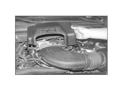
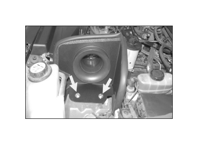
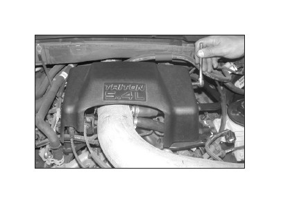
2. Remove the three engine cover bolts, then, remove the cover as shown.
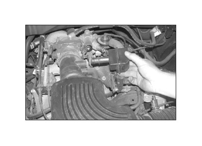
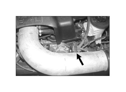
3. On vehicles with 5.4L engines, disconnect the crankcase vent hose and the idle air control vent hose from the stock intake tube as shown.
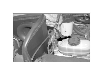
4. On 4.6L equipped vehicles, remove the idle air control hose and chamber as shown. Then, disconnect the crankcase vent hose from the factory intake tube.
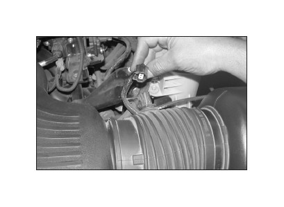
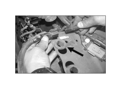
5. Disconnect the air temperature sensor electrical connection as shown.
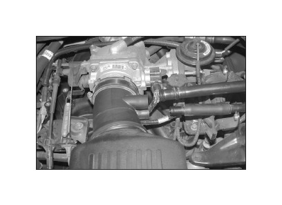
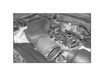
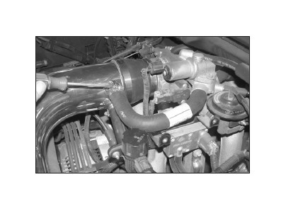
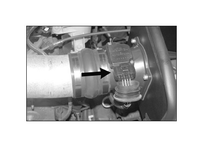
6. Loosen the hose clamps at the throttle body and at the air cleaner, then, remove the stock intake tube as shown.
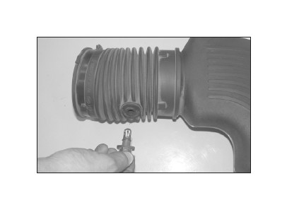
7. Remove the air temperature sensor from the stock intake tube as shown.
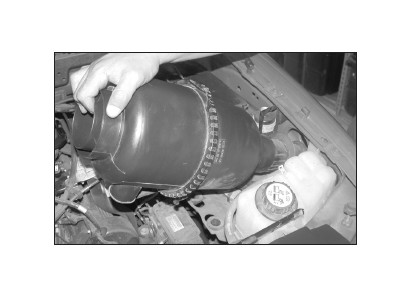
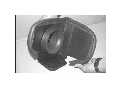
8. Pull firmly upwards to release the air cleaner assembly from the stock grommets located on the inner fender.
NOTE: K&N Engineering, Inc., recommends that customers do not discard factory air intake.
9. Unclip the mass air sensor wire harness from the air cleaner tray, then, disconnect the secondary mass air sensor electrical connection and remove the air cleaner assembly.
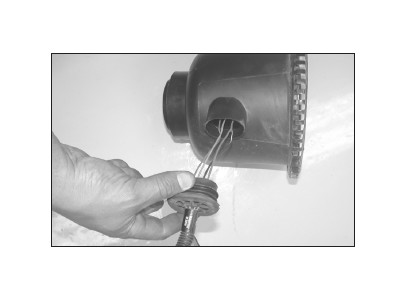
10. Disassemble the air cleaner assembly, then, pull the plastic wire cover and rubber boot back on the mass air electrical connection as shown.
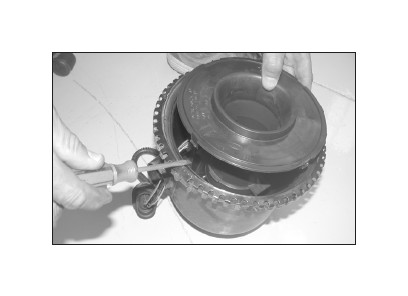
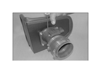
11. Using a flat blade screwdriver release the housing cover and pull up as shown.
12. Disconnect the mass air sensor electrical connection as shown.
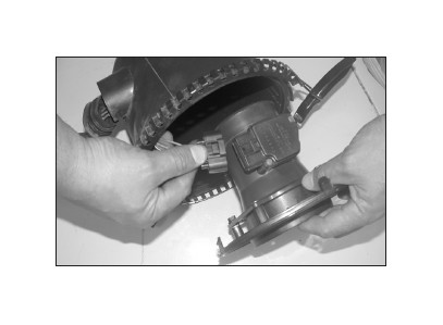
13. Remove the mass air sensor from the housing cover as shown.
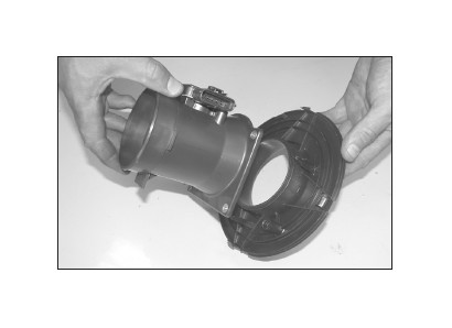
14. Bolt the stock mass air sensor onto the provided heat shield using the provided mass air adapter, gaskets and the provided hardware as shown.
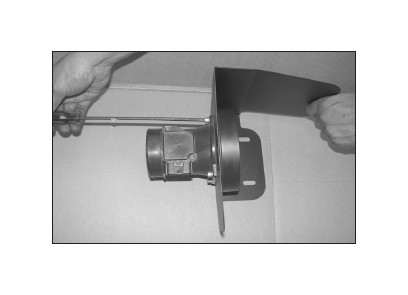
15. Install the provided edge trim onto the heat shield as shown.
16. Install the silicone hump hose and hose clamps onto the mass air sensor and tighten as shown.
17. Install the heat shield assembly into the vehicle and secure it to the stock air cleaner grommets using the provided hardware but do not tighten completely at this time.
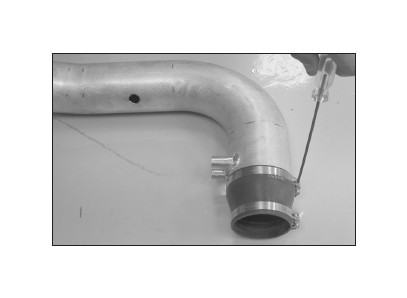
18. Install the provided silicone step hose and hose clamps onto the K&N® intake tube and tighten as shown.
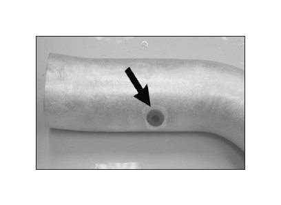
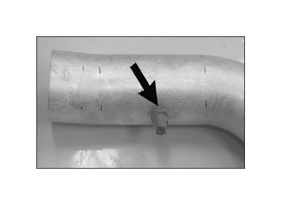
19. Install the provided rubber grommet into the hole on the K&N® intake tube as shown.
20. Install the air temperature sensor from step 8 into the rubber grommet as shown.
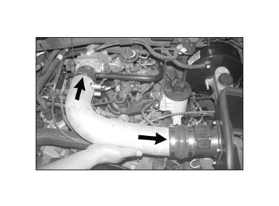
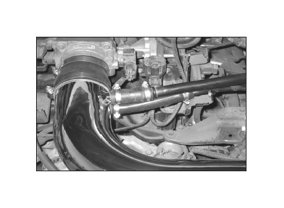
21. Slide the K&N® intake tube into the silicone hump hose, then, slide the silicone step hose onto the throttle body as shown.
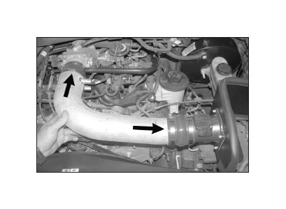
22. Line everything up for best fit and clearance then tighten all hose clamps.
23. Install the provided 5/8” silicone hose onto the stock plastic crankcase vent line. Then, install the open end of the 5/8” ID silicone hose onto the K&N® intake tube and secure with the provided hose clamps.
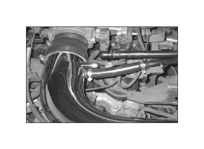
24. On vehicles equipped with a 4.6L engine, attach the provided 5/8”id idle air by-pass vent hose onto the appropriate fitting on the K&N® intake tube, trim for proper fitment to prevent the hose from developing a kink and attach the open end to the idle air by-pass valve.
25. On V8-5.4L models slide the provided 5” long silicone hose onto the hard line, then trim hose for best fit before connecting to the vent on the K&N® intake tube as shown.
26. Reconnect the air temperature sensor electrical connection as shown.
27. Re-install the engine cover and secure with the stock bolts.
28. Reconnect the secondary mass air electrical connection as shown.
29. Reconnect the primary mass air sensor electrical connection as shown.
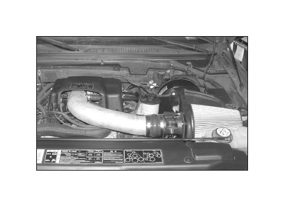
30. Install the K&N® air filter and secure with the provided hose clamp as shown.

31. Reconnect the vehicle’s negative battery cable. Double check to make sure everything is tight and properly positioned before starting the vehicle.
32. The C.A.R.B. exemption sticker, (attached), must be visible under the hood so that an emissions inspector can see it when the vehicle is required to be tested for emissions. California requires testing every two years, other states may vary.
33. It will be necessary for all K&N® high flow intake systems to be checked periodically for realignment, clearance and tightening of all connections. Failure to follow the above instructions or proper maintenance may void warranty.
ROAD TESTING:
1. Start the engine with the transmission in neutral or park, and the parking brake engaged. Listen for air leaks or odd noises. For air leaks secure hoses and connections. For odd noises, find cause and repair before proceeding. This kit will function identically to the factory system except for being louder and much more responsive.
2. Test drive the vehicle. Listen for odd noises or rattles and fix as necessary.
3. If road test is fine, you can now enjoy the added power and performance from your kit.
4. K&N Engineering, Inc., suggests checking the air filter element periodically for excessive dirt build-up. When the element becomes covered in dirt (or once a year), service it according to the instructions on the Recharger® service kit, part number 99-5050 or 99-5000.
