 FREE 1 to 3-Day Delivery on Orders $149+ Details
How to Install K&N Series 77 High Flow Performance Cold Air Intake w/ Coolant Reservoir - Black on your F-150
Installation Time
1 hours
Tools Required
- Flat Blade Screwdriver
- Ratchet
- Extension
- 14mm Socket
- 13mm Socket
- 10mm Socket
- 13mm Wrench
- 10mm Wrench
- 8mm Wrench
- T-20 Torx
- 3mm Allen Wrench
- 5mm Allen Wrench

Shop Parts in this Guide
PARTS LIST:
NOTE: FAILURE TO FOLLOW INSTALLATION INSTRUCTIONS AND NOT USING THE PROVIDED HARDWARE MAY DAMAGE THE INTAKE TUBE, THROTTLE BODY AND ENGINE.
TO START:
1. Turn off the ignition and disconnect the negative battery cable.
NOTE: Disconnecting the negative battery cable erases pre-programmed electronic memories. Write down all memory settings before disconnecting the negative battery cable. Some radios will require an anti-theft code to be entered after the battery is reconnected. The anti-theft code is typically supplied with your owner’s manual. In the event your vehicles’ anti-theft code cannot be recovered, contact an authorized dealership to obtain your vehicles anti-theft code. NOTE: Be sure the engine is completely cooled before proceeding with the intake kit instructions.
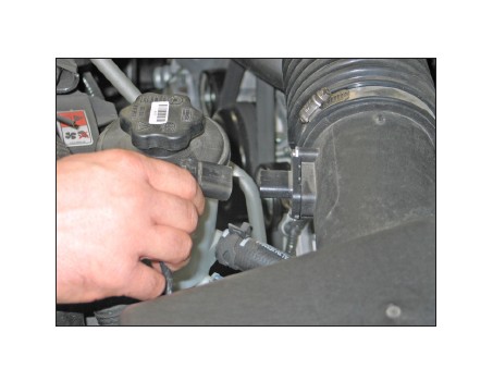
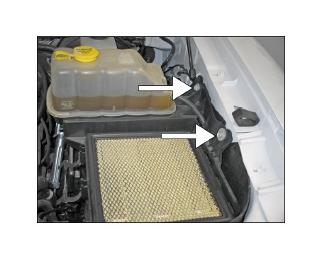
2. Release the red locking tab and then disconnect the mass air sensor electrical connection.
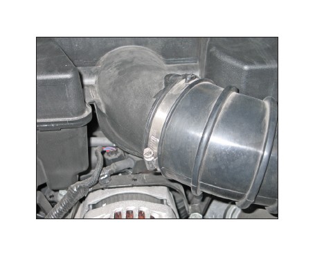
3. Loosen the hose clamp that secures the intake tube to the intake plenum.
4. Release the three retaining clips on the upper air box.
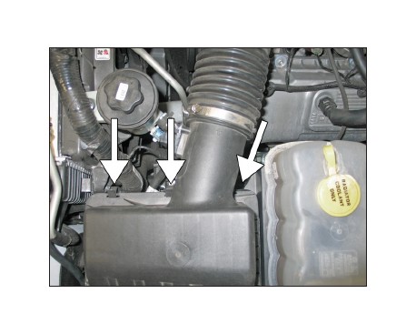
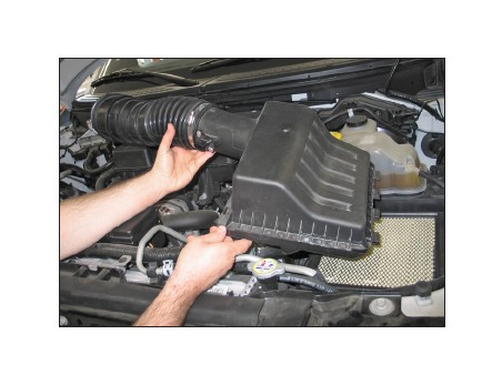
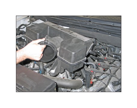
5. Remove the upper air box and intake tube assembly from the vehicle.
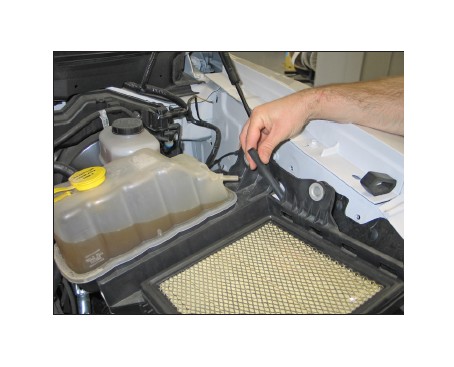
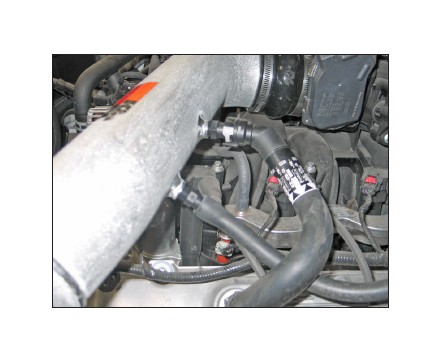
6. Disconnect the EVAP hose from the intake plenum.
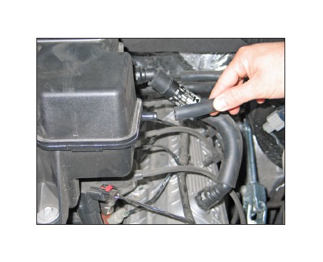
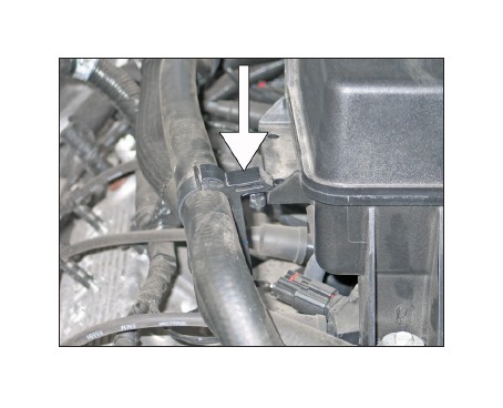
7. Release the locking tab and then disconnect the crankcase vent hose from the intake plenum.
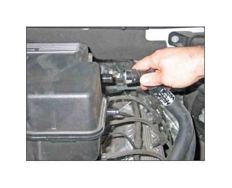
8. Unhook the heater hose retaining clip from the intake plenum.
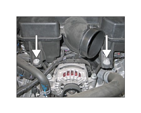
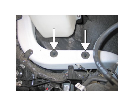
9. Remove the two bolts that secure the intake plenum to the intake manifold.
10. Loosen the hose clamp securing the intake plenum to the throttle body.
11. Remove the intake plenum from the vehicle.
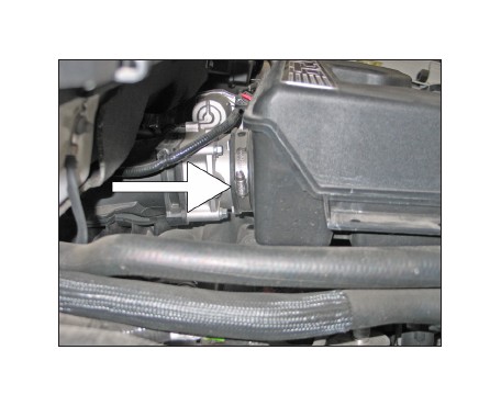
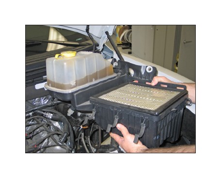
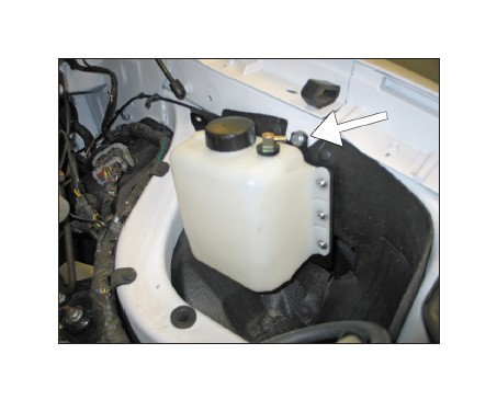
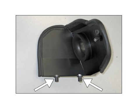
12. NOTE: Be sure the engine is completely cooled before proceeding with this step. Remove the two bolts that secure the lower air box/coolant reservoir to the inner fender.
NOTE: Some vehicles may be equipped with an alarm sensor that may need to be removed to gain access the rear most mounting bolts.
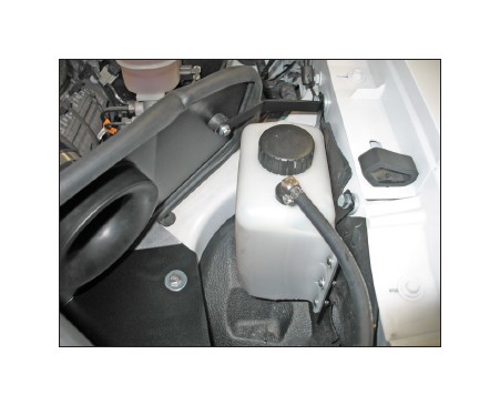
13. Lift the lower air box/coolant reservoir up to release it from the mounting grommets. Lean the coolant reservoir inward towards the engine, disconnect the coolant transfer hose from the coolant reservoir.
NOTE: Use care when disconnecting the coolant transfer hose so coolant is not spilled.
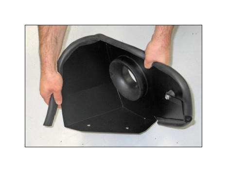
14. Remove the lower air box/coolant reservoir assembly from the vehicle.
NOTE: K&N Engineering, Inc., recommends that customers do not discard factory air intake.
15. Attach the provided coolant reservoir bottle to mounting bracket (083144) using the provided hardware.
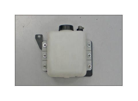
16. Secure the coolant bottle assembly to the inner fender using the provided hardware and spacer.
NOTE: Only the front of the bracket will be mounted at this time. The spacer is to be placed between the inner fender and bracket.
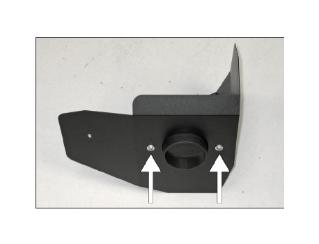
17. Install the filter adapter into the heat shield and secure with the provided hardware.
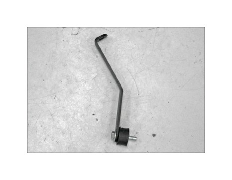
18. Install the provided rubber mounted stud onto the heat shield mounting bracket (083143) using the provided hardware.
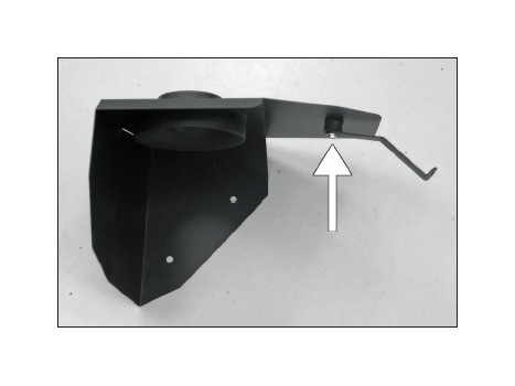
19. Install the bracket assembly onto the heat shield and secure with the provided hardware.
20. Install the provided edge trim onto the heat shield as shown.
NOTE: Some trimming of the edge trim will be necessary.
21. Install the provided nut inserts into the heat shield using the provided hardware.
22. Remove the factory air box mounting grommets from the inner fender brace.
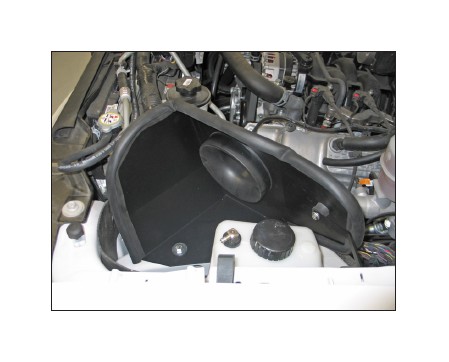
23. Install the heat shield assembly into the vehicle so the inserts align with the air box mounting grommet locations. Secure the heat shield mounting bracket to the inner fender with the coolant reservoir and spacer provided. Then secure the bottom of the heat shield to the inner fender brace with the inserted nuts.
NOTE: On vehicles equipped with an alarm sensor, reattach the alarm sensor with the original bolt in its original location.
24. Route the coolant reservoir transfer hose to the coolant reservoir. Trim the hose for proper fit, then attach the hose onto the fitting and secure with the provided hose clamp.
NOTE: Transfer the remaining coolant from the factory reservoir into the new coolant reservoir bottle.
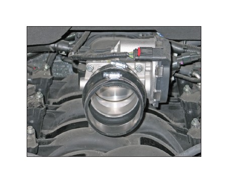
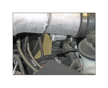
25. Install the provided silicone hose (084057) onto the throttle body and secure with provided hose clamp.
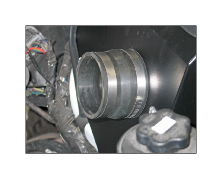
26. Install the provided silicone hose (08051) onto the filter adapter and secure with the provided hose clamp.
27. Remove the two screws securing the mass air sensor into the upper air box housing, then remove the mass air sensor from the housing.
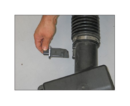
28. Install the mass air sensor into the K&N® intake tube and secure with the provided hardware.
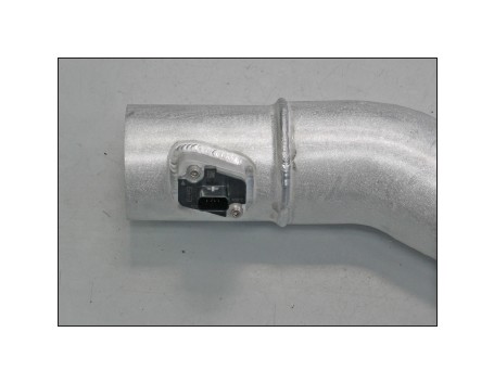
29. Install the provided quick disconnect fitting into the K&N® intake tube as shown.
NOTE: Plastic NPT fittings are easy to cross thread. Install the vent fitting “hand” tight, then turn it two complete turns with a wrench.
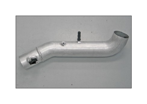
30. Install the ½” hose fitting into the K&N® intake tube as shown.
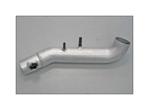
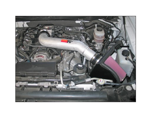
31. Install the K&N® intake tube into the silicone hose attached to the filter adapter. Insert the intake tube’s opposite end into the silicone hose on the throttle body, secure each end with the provided hose clamps.
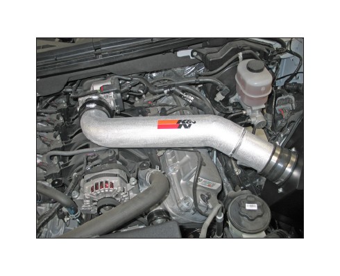
32. Connect the crankcase vent hose to the quick disconnect fitting. Attach the EVAP hose to the ½” hose barb.
33. Connect the mass air sensor electrical connection.
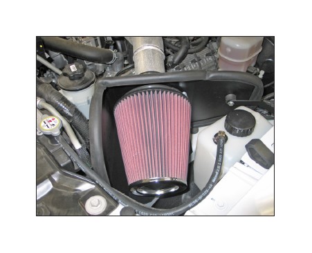
34. Mount the K&N® air filter onto the filter adapter and secure with a provided hose clamp. Transfer the coolant from the factory reservoir into the K&N® coolant reservoir.
NOTE: Drycharger® air filter wrap; part # RF-1020DK is available to purchase separately. To learn more about Drycharger® filter wraps or look up color availability please visit http://www.knfilters.com®.
35. Reconnect the vehicle’s negative battery cable. Double check to make sure everything is tight and properly positioned before starting the vehicle.
36. The C.A.R.B. exemption sticker, (attached), must be visible under the hood so that an emissions inspector can see it when the vehicle is required to be tested for emissions. California requires testing every two years, other states may vary.
37. It will be necessary for all K&N® high flow intake systems to be checked periodically for realignment, clearance and tightening of all connections. Failure to follow the above instructions or proper maintenance may void warranty.
ROAD TESTING:
1. Start the engine with the transmission in neutral or park, and the parking brake engaged. Listen for air leaks or odd noises. For air leaks secure hoses and connections. For odd noises, find cause and repair before proceeding. This kit will function identically to the factory system except for being louder and much more responsive.
2. Test drive the vehicle. Listen for odd noises or rattles and fix as necessary.
3. If road test is fine, you can now enjoy the added power and performance from your kit.
4. K&N Engineering, Inc., requires cleaning the intake system’s air filter element every 100,000 miles. When used in dusty or off-road environments, our filters will require cleaning more often. We recommend that you visually inspect your filter once every 25,000 miles to determine if the screen is still visible. When the screen is no longer visible some place on the filter element, it is time to clean it. To clean and re-oil, purchase our filter Recharger® service kit, part number 99-5050 or 99-5000 and follow the easy instructions.

