 FREE 1 to 3-Day Delivery on Orders $149+ Details
How to Install K&N Series 57 FIPK Cold Air Intake w/ Heat Shield on your F-150
Installation Time
1 hours
Tools Required
- 9/16” Socket
- 5mm Allen
- 10mm Socket
- 13mm Socket
- 10mm Wrench
- Flat Blade Screwdriver
- Extension
- Ratchet

Shop Parts in this Guide
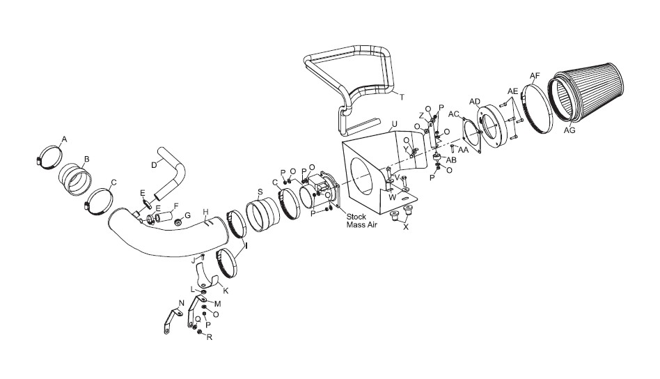
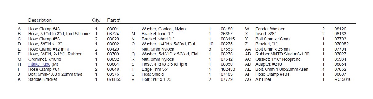
PARTS LIST:
NOTE: FAILURE TO FOLLOW INSTALLATION INSTRUCTIONS AND NOT USING THE PROVIDED HARDWARE MAY DAMAGE THE INTAKE TUBE, THROTTLE BODY AND ENGINE.
TO START:
1. Turn off the ignition and disconnect the negative battery cable.
NOTE: Disconnecting the negative battery cable erases pre-programmed electronic memories. Write down all memory settings before disconnecting the negative battery cable. Some radios will require an anti-theft code to be entered after the battery is reconnected. The anti-theft code is typically supplied with your owner’s manual. In the event your vehicles’ anti-theft code cannot be recovered, contact an authorized dealership to obtain your vehicles anti-theft code.
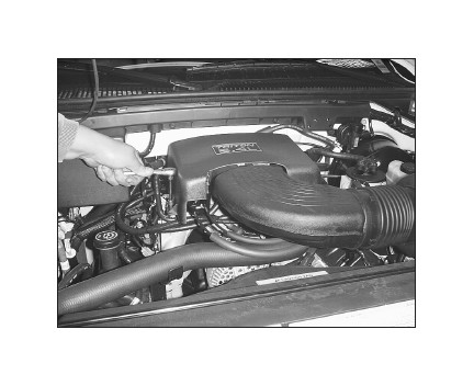
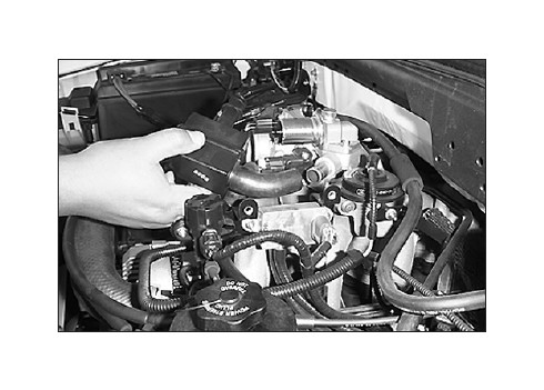
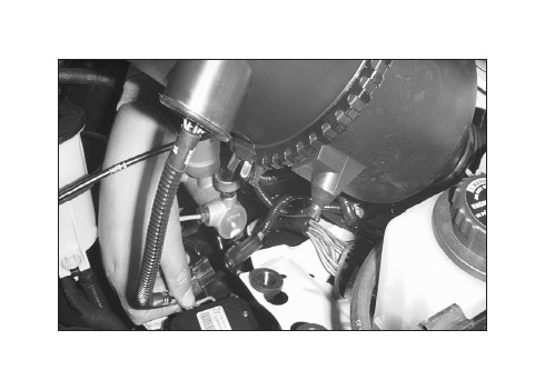
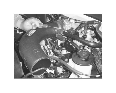
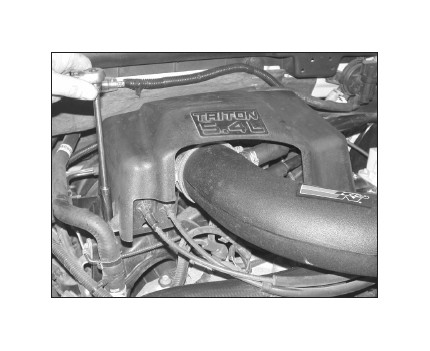
2. Loosen and remove the three bolts that retain the throttle body cover, then remove the cover.
3. Disconnect the air temperature sensor electrical connection.
4a. On models with 4.6L engines, detach the air bypass valve and crank case vent hose from the stock intake tube.
4b. On models with 5.4L engines, detach the idle air control and crank case vent hose from the stock intake tube.
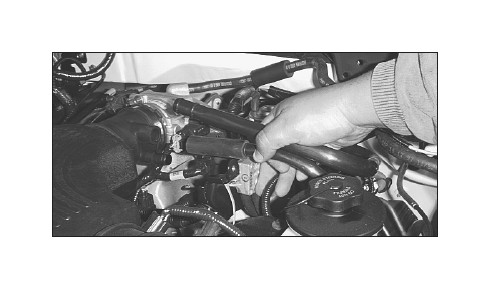
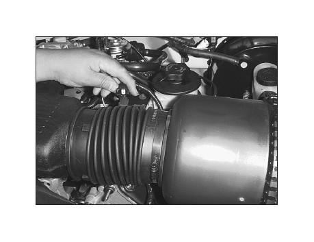
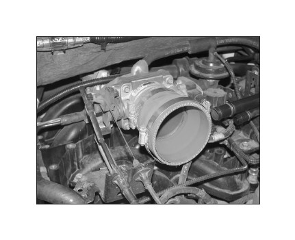
5. Loosen the hose clamp on the stock intake tube at the throttle body.
6. Detach the stock intake tube from the throttle body and lift up on the air cleaner assembly to release it from it’s retaining grommets.
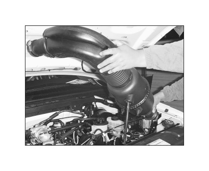
7. Disconnect the secondary mass air sensor electrical connection.
8. Remove the entire stock air intake assembly from the vehicle.
NOTE: K&N Engineering, Inc., recommends that customers do not discard factory air intake.
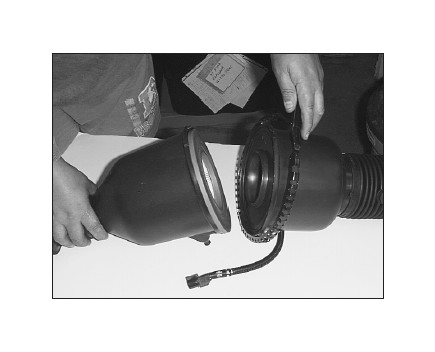
9. Open the air cleaner assembly and isolate the mass air sensor assembly.
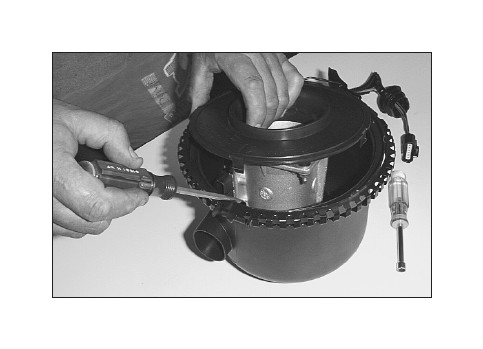
10. Slide the rubber grommet back and disconnect the primary mass air sensor electrical connection, using a flat blade screwdriver.
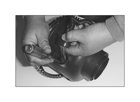
11. Using a flat blade screwdriver, push in and release the four clips that retain the mass air sensor retaining plate.
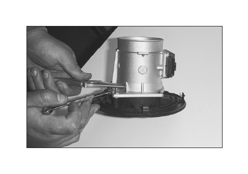
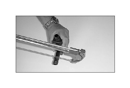
12. Using a pair of small vise grips or pliers, hold the stud while using a 10mm wrench to loosen the nuts, then remove the mass air sensor from the retaining plate.
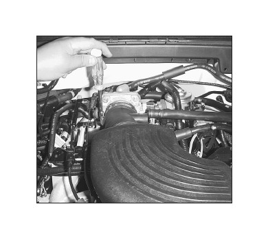
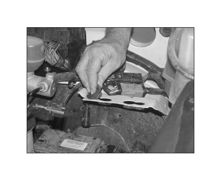
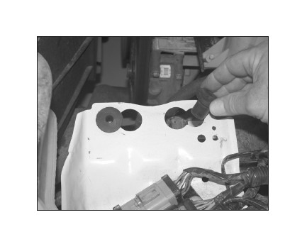
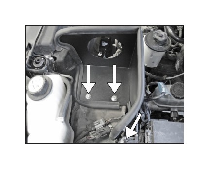
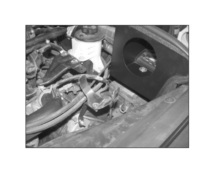
13. Remove the two air box mounting grommets from vehicle as shown.
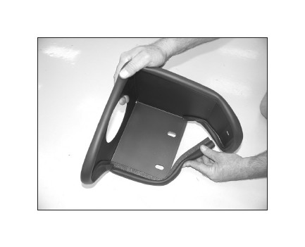
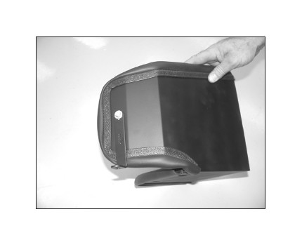
14. Install edge trim onto the heat shield as shown. Trim if needed.
15. Remove the 6mm bolt that retains the cruise control onto the vehicle.
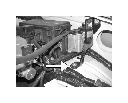
15a. On vehicles without cruise control, install the rubber mounted stud onto the vehicle as shown.
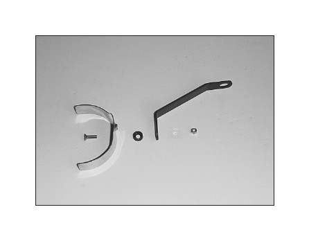
16. Install the provided “L” bracket (070952) onto the heat shield as shown.
NOTE: Install a washer between the heat shield and bracket.
17. Install the two nut inserts into the air box mounting tray as shown.
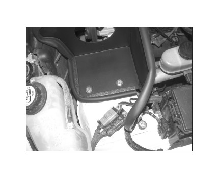
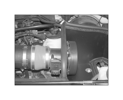
18. On vehicles equipped with cruise control, set the heat shield into position on the air filter mounting bracket. Then secure the heat shield with the provided hardware as shown.
NOTE: Be sure the mounting bracket and cruise control are secured together.
18a. On vehicles not equipped with cruise control, set the heat shield into position on the air filter mounting bracket and then secure the heat shield with the provided hardware as shown.
NOTE: The heat shield mounting bracket will be secured to the rubber mounted stud installed in step #15a.
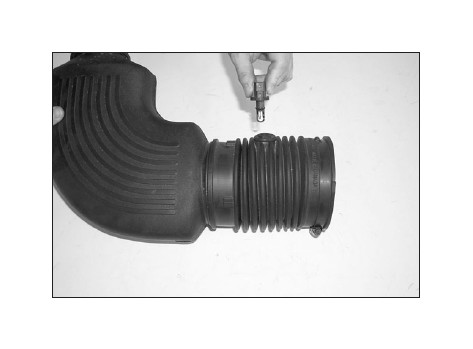
19. Remove the air temp. sensor from the stock air intake tube as shown.
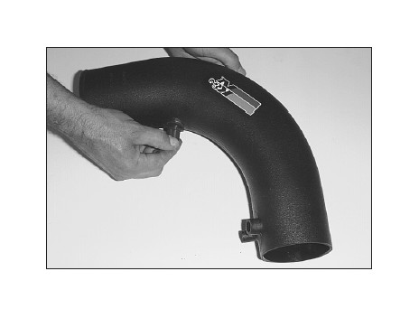
20. Using the provided grommet, install the air temperature sensor into the K&N® intake tube.
21. Assemble the saddle to the appropriate bracket using the provided hardware as shown.
NOTE: For vehicles equipped with the 4.6L engine, use the long “L” bracket (26657) and for vehicles equipped with the 5.4L engine, use the short “L” bracket (083115).
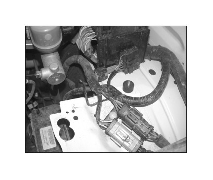
22. Install the saddle bracket assembly onto the protruding stud as shown, secure into place using the provided hardware.
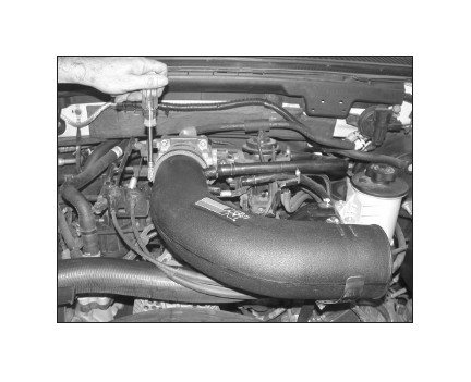
23. Using the provided hose clamp, attach the silicone hose (08724) to the throttle body.
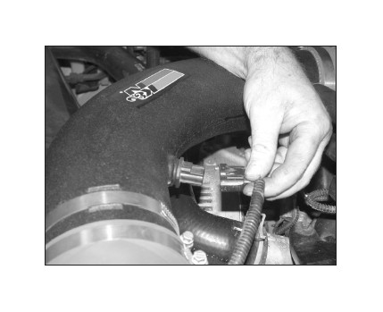
24. Install the K&N® intake tube onto the throttle body and tighten the hose clamp.
25. On models with 5.4L engines, install the idle air control and crank case vent hose onto the appropriate fittings on the K&N® intake tube, secure with the hose clamps provided.
NOTE: On vehicles equipped with a 4.6L engine, attach the provided 5/8”id idle air by-pass vent hose onto the appropriate fitting on the K&N® intake tube, trim for proper fitment to prevent the hose from developing a kink and attach the open end to the idle air by-pass valve.
26. On models equipped with 4.6L engines: In some insulated instances where a whistling noise may exist, do as follows. Cut the flange of the air bypass valve just past the last barb. Reinstall the air bypass valve, attaching it to the appropriate fitting on the intake tube using the 5/8”id hose and provided hose clamps.
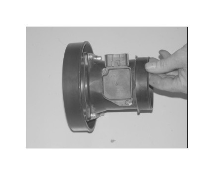
27. Attach the mass air adapter to the mass air sensor using the gasket and provided hardware.
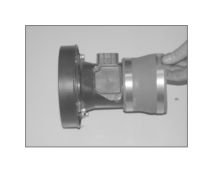
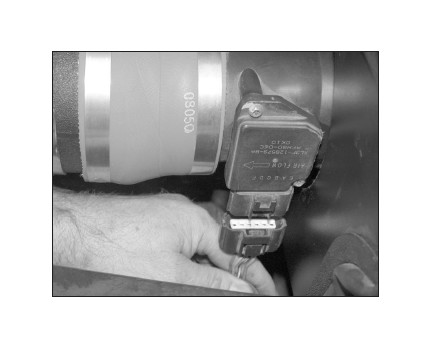
28. Install the silicone hose (#08050) onto the mass air sensor with the provided hardware as shown.
29. Attach the mass air assembly to the intake tube. Secure the mass air assembly and saddle bracket to the intake tube using the provided hose clamps.
30. Reconnect the primary and secondary mass air electrical connections.
31. Reconnect the air temp. sensor electrical connection.
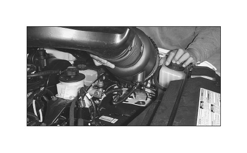
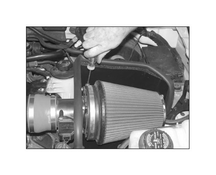
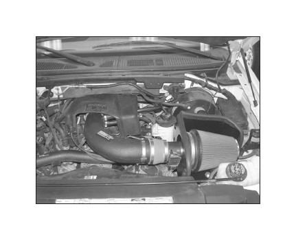
32. Install the K&N® air filter onto the mass air adapter and secure it with the provided hose clamp.
33. Reinstall the engine cover removed in step #2.
34. Reconnect the vehicle’s negative battery cable. Double check to make sure everything is tight and properly positioned before starting the vehicle.
35. The C.A.R.B. exemption sticker, (attached), must be visible under the hood so that an emissions inspector can see it when the vehicle is required to be tested for emissions. California requires testing every two years, other states may vary.
36. It will be necessary for all K&N® high flow intake systems to be checked periodically for realignment, clearance and tightening of all connections. Failure to follow the above instructions or proper maintenance may void warranty.
ROAD TESTING:
1. Start the engine with the transmission in neutral or park, and the parking brake engaged. Listen for air leaks or odd noises. For air leaks secure hoses and connections. For odd noises, find cause and repair before proceeding. This kit will function identically to the factory system except for being louder and much more responsive.
2. Test drive the vehicle. Listen for odd noises or rattles and fix as necessary.
3. If road test is fine, you can now enjoy the added power and performance from your kit.
4. K&N Engineering, Inc., requires cleaning the intake system’s air filter element every 100,000 miles. When used in dusty or off-road environments, our filters will require cleaning more often. We recommend that you visually inspect your filter once every 25,000 miles to determine if the screen is still visible. When the screen is no longer visible some place on the filter element, it is time to clean it. To clean and re-oil, purchase our filter Recharger® service kit, part number 99-5050 or 99-5000 and follow the easy instructions.

