 FREE 1 to 3-Day Delivery on Orders $149+ Details
How to Install K&N Series 57 FIPK Cold Air Intake on your F-150
Installation Time
1 hours
Tools Required
- Ratchet
- Extension
- 5/16” Socket
- 4mm Socket
- T20 Torx
- 9/16” Wrench
- 4mm Allen
- 3mm Allen
- Flat Blade Screwdriver

Shop Parts in this Guide
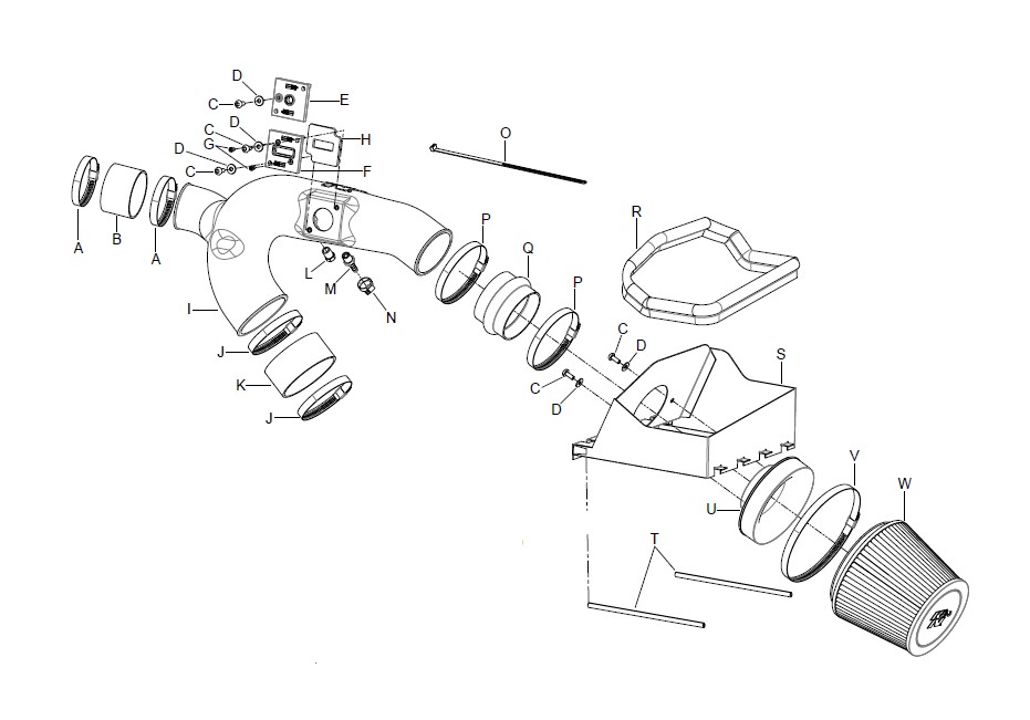
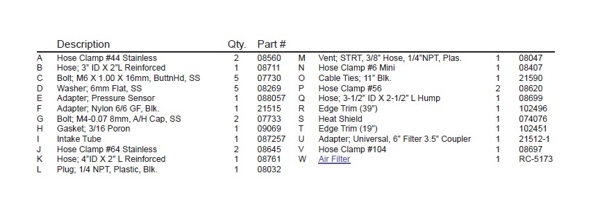
PARTS LIST:
NOTE: FAILURE TO FOLLOW INSTALLATION INSTRUCTIONS AND NOT USING THE PROVIDED HARDWARE MAY DAMAGE THE INTAKE TUBE, THROTTLE BODY AND ENGINE.
TO START:
1.Turn off the ignition and disconnect the negativebattery cable.
NOTE: Disconnecting the negative battery cableerases pre-programmed electronic memories.Write down all memory settings beforedisconnecting the negative battery cable. Someradios will require an anti-theft code to beentered after the battery is reconnected. Theanti-theft code is typically supplied with yourowner’s manual. In the event your vehicles’anti-theft code cannot be recovered, contact anauthorized dealership to obtain your vehiclesanti-theft code.
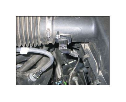
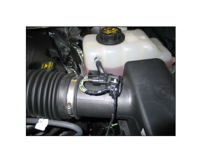
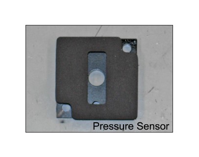
2.On vehicles equipped with a mass air sensor,release the red locking tab and then disconnect themass air sensor electrical connection. On vehiclesequipped with a pressure sensor, disconnect theelectrical connection and then unhook the wiringharness from the stud.
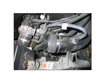
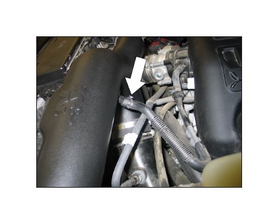
3.On vehicles equipped with the EVAP vent line,disconnect the EVAP vent line from the factoryintake tube.
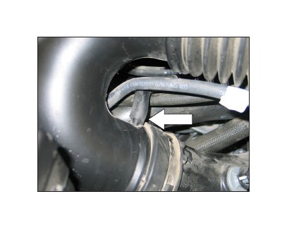
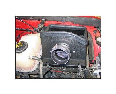
4.Loosen the three hose clamps securing thefactory intake tube.
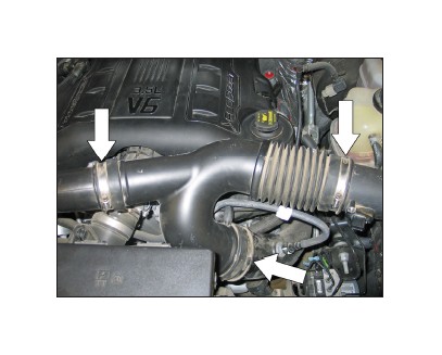
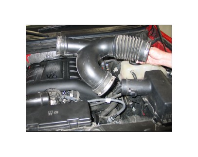
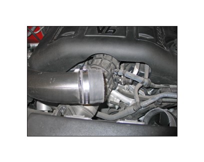
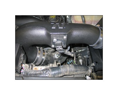
5.Remove the factory intake tube as shown.NOTE: DO NOT remove the air diverters fromthe factory turbo inlet tubes.
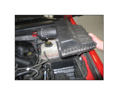
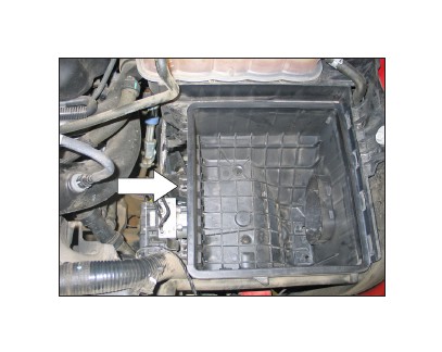
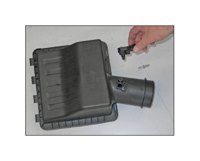
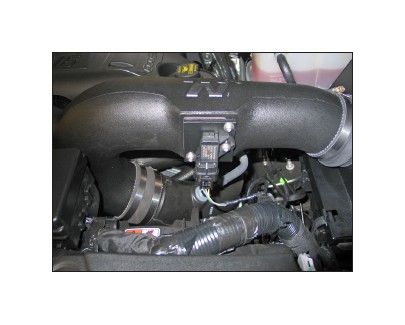
6.Release the three locking tabs and then lift upand remove the upper air box from the vehicle.
NOTE: K&N Engineering, Inc., recommends thatcustomers do not discard factory air intake.
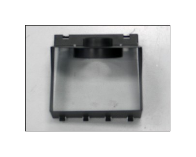
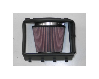
7.Install the filter adapter into the heat shield andsecure with the provided hardware.
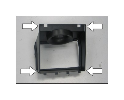
8.Install the provided “Top Bulb” edge trim aroundthe top of the heat shield as shown.
NOTE: Some trimming of the edge trim will benecessary.
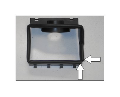
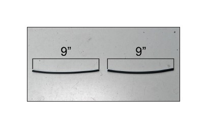
9. Cut the provided 1/16” gap edge trim into two sections 9” long.
10. Install the 1/16” gap edge trim onto the bottom of the heat shield as shown.
11. Install the K&N® air filter onto the filter adapter and secure with the provided hose clamp.
NOTE: Drycharger® air filter wrap; part # RC-5173DK is available to purchase separately.
12. Install the provided silicone hump hose (08699) onto the filter adapter and secure with the provided hose clamp.
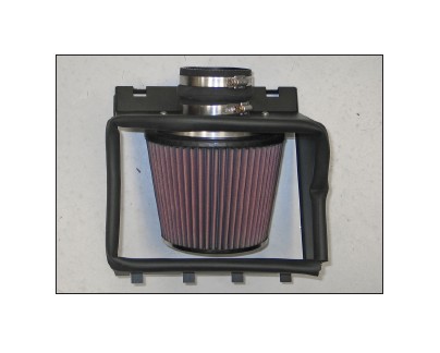
13. Remove the center upper air box retaining clip from the lower air box.
14. Install the air filter/heat shield assembly onto the lower air box and secure with the two remaining air box clips.
15. Install the provided silicone hose (08761) onto the driver’s side turbo inlet tube and secure with the provided hose clamp.
16. Install the provided silicone hose (08711) onto the passenger side turbo inlet tube and secure with the provided hose clamp.
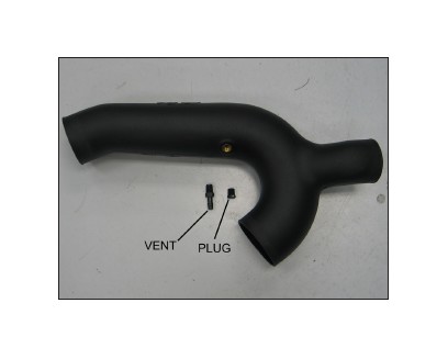
17. On vehicle equipped with an EVAP vent line, install the npt vent fitting into the K&N® intake tube. On vehicles not equipped with an EVAP vent line, install the npt plug.
NOTE: Plastic NPT fittings are easy to cross thread. Install the vent fitting “hand” tight, then turn it two complete turns with a wrench.
18. With vehicles equipped with a mass air sensor, install the provided gasket onto the mass air sensor adapter. On vehicles equipped with a pressure sensor, install the provided gasket onto the pressure sensor adapter as shown.
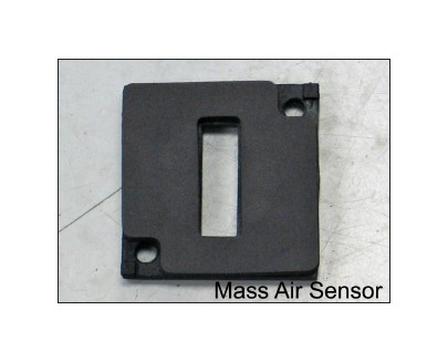
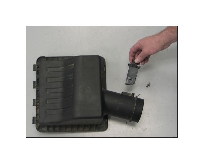
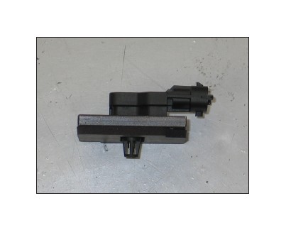
19. If the vehicle is equipped with a mass air sensor, remove the two bolts securing the mass air sensor into the factory air box and then remove the sensor from the air box.
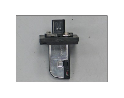
20. Install the mass air sensor into the mass air sensor adapter and secure with the provided hardware.
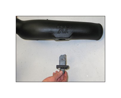
21. Install the mass air sensor assembly into the K&N® intake tube and secure with the provided hardware.
NOTE: The opening in the mass air sensor should be oriented to face the filter end of the tube.
22. If the vehicle is equipped with a pressure sensor, remove the bolt securing the pressure sensor into the factory air box, and then remove the sensor from the air box.
23. Install the pressure sensor into the pressure sensor adapter and secure with the provided hardware.
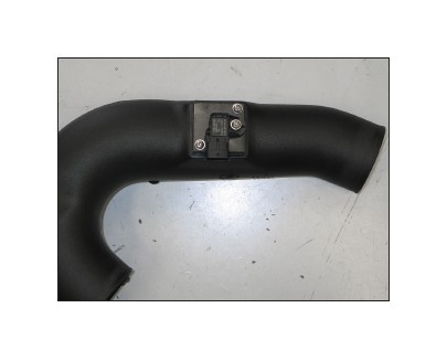
24.Install the pressure sensor assembly into theK&N® intake tube and secure with the providedhardware.
NOTE: The electrical connector should be oriented downward once installed.
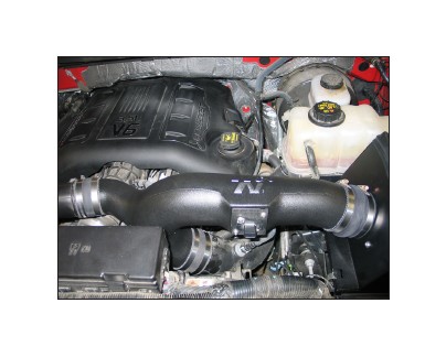
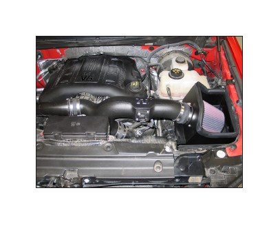
25.Install the K&N® intake tube assembly,attaching each inlet into the silicone hosespreviously installed. Secure the intake tube with theprovided hose clamps.
26.On vehicles equipped with an EVAP vent line,install the EVAP vent hose onto the vent fitting andsecure with the provided hose clamp.
27.Reconnect the mass air sensor or pressuresensor electrical connection. Secure the sensorwiring harness to the main harness with theprovided tie wrap.
28.Reconnect the vehicle’s negative battery cable.Double check to make sure everything is tight andproperly positioned before starting the vehicle.
29.The C.A.R.B. exemption sticker, (attached),must be visible under the hood so that an emissions inspector can see it when the vehicle isrequired to be tested for emissions. Californiarequires testing every two years, other states mayvary.
30.It will be necessary for all K&N® high flow intakesystems to be checked periodically for realignment,clearance and tightening of all connections.Failure to follow the above instructions or propermaintenance may void warranty.
ROAD TESTING:
1.Start the engine with the transmission in neutralor park, and the parking brake engaged. Listen forair leaks or odd noises. For air leaks secure hosesand connections. For odd noises, find cause andrepair before proceeding. This kit will functionidentically to the factory system except for beinglouder and much more responsive.
2.Test drive the vehicle. Listen for odd noises orrattles and fix as necessary.
3.If road test is fine, you can now enjoy the addedpower and performance from your kit.
4.K&N Engineering, Inc., requires cleaning theintake system’s air filter element every 100,000 miles. When used in dusty or off-roadenvironments, our filters will require cleaning more often. We recommend that you visually inspectyour filter once every 25,000 miles to determineif the screen is still visible. When the screen is nolonger visible some place on the filter element, it istime to clean it. To clean and re-oil, purchase ourfilter Recharger® service kit, part number 99-5050or 99-5000 and follow the easy instructions.
