FREE 1 to 3-Day Delivery on Orders $149+ Details
How to Install KC HiLiTES Rocker Switch w/ LED Indicator - Green (97-18 All) on your Ford F-150
Thanks for choosing a KC HiLiTES product. We take pride in building the highest quality, best engineered systems possible. Your satisfaction with our product is important, so if you have any questions or comments, please call our customer service line at 800-528-0950 or visit our web site at www.kchilites.com.
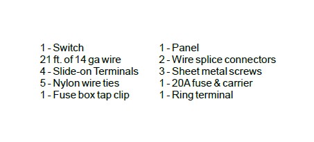
1. PARTS INCLUDED IN YOUR WIRING KIT...
2.MOUNT‘EM UP...
DRIVING LIGHTS - Where you mount your driving lights is extremely important, as well as aiming the units. Too high and they will bounce right back at you and you’ll be trying to look through the beam instead of down the road. Too low and they’ll skim across the roadway and not illuminate correctly where you are trying to see. Fortunately, the bumper on most vehicles works out perfectly. Mounting right under or on top of it is ideal. Try and place the lights as far back toward the grill as possible, this will keep the front of the lens behind the bumper and minimize the chance of breakage from impact.
FOG LIGHTS - Since fog rarely settles right onto the roadway, fog lights will perform most effectively when mounted low and aimed underneath the fog.
BUMPER MOUNTING - Choose a location on your bumper for mounting your lights, ensuring they measure an equal distance from each end of the bumper. After marking the location for mounting, drill the appropriate size hole for the lights you are mounting. Install the lights and loosely tighten the nut (you will secure them later after aiming).
3.GET YOUR LIGHTS WIRED...
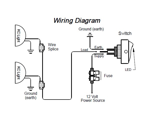
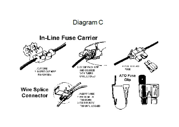
a.Find a suitable location inside the passenger compartment for your switch, mark and drill two 1/8” holes and loosely install the panel. Fit switch in panel Diagram C and tighten switch. (we will remove panel when attaching wires)
b.Ground both of the black wires coming out of the lights. In most cases you can attach them to the mounting bolts. If the mounting surface is not metal then you must extend the wires to a good chassis ground.
c. Starting from the light farthest from the panel, attach one end of the supplied wire to the red wire coming out of the light using one of the wire splice connectors (see diagram C). If there is a terminal on the light wire, cut it off first. Continue routing the wire toward the panel to the second light and attach that red wire using another wire splice connector.
d.Continue routing the wire inside the engine compartment, through the firewall until you get to the switch and panel. Cut and strip the wire and crimp on a slide-on terminal. Connect this wire to the middle tab on the switch marked LOAD.
e.Find a metal surface to ground your switch. If the panel is mounted to a metal surface you may use one of the panel mounting screws for the ground. If not, find an existing screw nearby and cut a length of wire to go between the switch and ground point. Attach a ring terminal to one end and a slide-on terminal to the other. Connect one end of the wire to the switch tab marked EARTH (this is tab on same side as green LED light on switch, see wiring diagram below) and the other end to the grounded screw.
f.Attach a slide-on terminal to the remaining piece of wire and connect it to the switch tab marked SUPPLY( remaining tab). Route the other end to a 12 volt power source. This may be your fuse block, battery or other junction box. Before connecting to power source, install the in-line fuse carrier and If you have any problems or questions, please fuse as shown in diagram C. If you use the fuse block, attach a slide-on call customer service at 800-528-0950 terminal and either slip it on an open accessory lug or use the enclosed ATO fuse clip (see diagram C) and attach to existing fuse.
g.LIGHT ‘EM UP.
4.AIMING YOUR LIGHTS...
Proper aiming of your lights is important. This procedure is accomplished by aiming your fog or driving lights in relation to your properly aimed headlights.
1. Place your vehicle approximately 25 feet and perpendicular to a flat surface such as a garage door or building. It is important that the vehicle be on level ground.
2. With low beam headlights on, go over to the surface on which they are shining and mark the vertical center on both left and right headlights with something easily removable like masking tape. You might use a short piece of tape to show vertical center and a long piece for the horizontal portion. Your tape should appear as below.
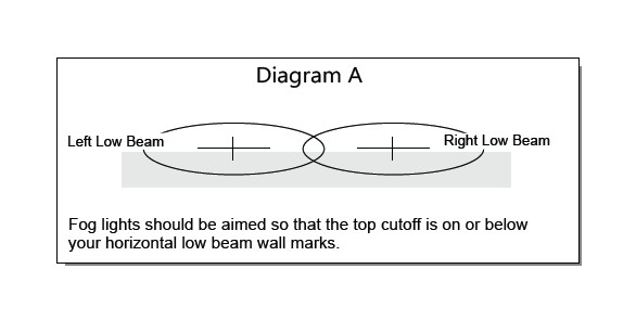
USE DIAGRAM “A” FOR AIMING FOG LIGHTS
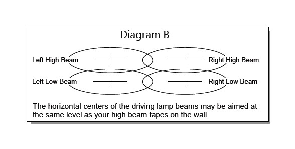
USE DIAGRAM “B” FOR AIMING DRIVING LIGHTS
With these markings on the wall, aiming can be done very easily. Please refer to the proper section below for the type of lights being aimed.
FOG LIGHTS - The vertical aiming of fog lights is very important. Because of the low mounting position relative to the ground (12 to 30 inches), they should be aimed parallel to the ground or lower. Fog lights should be aimed so the cutoff is on or below your horizontal low beam wall marks for best results. The side to side adjustments are up to you. A large center overlap will increase center light and decrease overall width. A slight center overlap will increase your side lighting and give even coverage overall.
DRIVING LIGHTS - Driving lights are used to supplement your high beams. They should only be used in conjunction with high beam headlights. The horizontal centers of the beams may be aimed at the same level as your high beam tape marks on the wall. The width is up to you as you may prefer to light the sides of the road at a distance rather than concentrating the majority of the light down the middle.
OFF ROAD LIGHTS - Since lights such as these are not legal on any public road or highway, aiming your off road or competition lights is entirely up to you. Most prefer the beam to shine as far down the road as possible, others adjust them slightly off to the sides.