FREE 1 to 3-Day Delivery on Orders $149+ Details
How to Install J.W. Speaker 7 in. Round Black LED Auxiliary Lights - Pair on your F-150
In the Box
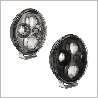
(x2) Model TS4000 Auxiliary Light
(x1) 2-Lamp Relay (in Kit Only)
Pre-Installed on Light:
(x2) 3/8"-16x3.00" Aiming Bolt
(x2) 3/8"-16 Nut
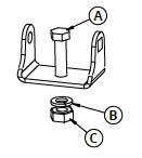
A. (x2) 3/8"-16 x 1.5" Mounting Bolt
B. (x2) M10 Split Lock Washer
C. (x2) 3/8"-16 Hex Nut
Single lights come with half of the above parts
Wire Functions
Black = Ground
Red = Power
Input Voltage: 12-24V DC
Operating Voltage: 9-32V DC
Pre-Installation Guidelines
1. Read all safety notes and mounting guidelines before installing the product. Verify that all parts listed under “In the Box” are present and complete.
2. Inspect the product for damage. DO NOT install the product if there is any damage. Contact the authorized retailer where you purchased it to initiate a warranty claim if there is damage.
3. Verify that all power supply and/or charging systems comply to the specified voltage limits for the light.
Installation Instructions
1. Turn off the vehicle and disconnect the power supply.
2. Ensure that the mounting location is a FLAT, SOLID surface of the same (or larger) size as the bracket or light. This will prevent warping or distortion that can cause cracking or damage to the light and/or bracket. There should also be a minimum of 1.25mm of space around the lamp in all directions.
3. Secure the light to the mounting surface then aim the light using the aiming bolt (directions on next page).
4. Check condition of all wires, connectors, mating connectors, and gaskets. All connections should be adequately protected against moisture. Shrink tubing is recommended.
5. Lay and secure the wiring so that no pulling or abrasion can occur. Proper installation requires there to be a little slack near the lamp to avoid pulling on the connector (which can create a path for water ingress). Wires should be adequately secured to avoid damage.
6. Carefully connect the wires using the “Wire Functions” and “Voltage” information above. Push firmly on the connector to ensure that it is properly mated with the lamp, creating a seal to protect against water ingress.
7. Aim the lights (instructions available on last page).
CAUTION:
A) STUDY THE COMPLETE INSTRUCTIONS AND SCHEMATIC BEFORE ATTEMPTING TO INSTALL WIRING. Planning your installation strategy prior to starting will minimize problems in placement of the relay and feeding wires through the firewall. (If after reading these instructions, you have questions or concerns about installing the kit yourself , please consult a qualified professional.)
B) Remove ground connections from the battery before attempting to connect electrical wires.
C) All wires should be secured through existing wire clamps or by taping or clamping to existing wires or cables.
D) To be legally compliant, auxiliary lights must be controlled in a way that they are only lit when the headlights are on. Daytime running lights should only be lit when the headlights are off.
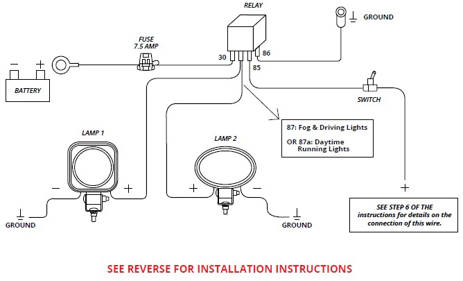
WIRING INSTRUCTIONS:
STEP 1: Attach the rocker switch to a place where it is easily reached from the driver seat. Suggested hole size 13/16".
STEP 2: Locate an accessible place in the engine compartment to mount the relay.
STEP 3: Feed a 16 gage wire from the relay mounting position to the switch. Use an existing hole around the steering column or speedometer cable. Do not use a hole with a moving part such as a clutch linkage. Crimp the supplied terminals to either end of the wire. Attach the wire between the switch and relay terminal #85.
STEP 4: Trace the wires running from the headlights back as close as possible to the firewall. To wire the kit correctly, it must be connected to the wire that powers the appropriate headlight function. Turn on the low beams and test for voltage or continuity. The hot wire will be the low beam. (Caution: Do not test the headlamp wires with the high beams turned on, since both wires may be hot.)
STEP 5: Attach a second 16 gage wire to the switch using supplied terminals and feed the second end through the firewall to the location identified in step 4. Use an existing hole around the steering column or speedometer cable. Do not use a hole with a moving part such as a clutch linkage.
STEP 6: Splice the second wire from the switch into the wire appropriate for the lamp function. Driving lamps use the high beam wire. Fog and DRL lamps use the low beam wire.
STEP 7: Connect relay terminal #86 to ground using a 16 gage wire and the supplied terminal and grounding ring.
STEP 8: Attach the positive wires from the lamps to the relay using the supplied terminals. Use relay terminal #87 for fog and driving lights or terminal #87a for daytime running lights.
STEP 9: Connect the ground wires from the lamp to an automotive ground. (Note: Some bumpers may not be adequately grounded. Ground the lamp to the chassis for a more robust connection.)
STEP 10: Attach relay terminal #30 to the fuse holder using the supplied terminals and a 16 gage wire. Feed wire from the fuse holder to the battery and attach to the positive terminal using the supplied 8 mm ring terminal.
STEP 11: Secure all wires and install the 7.5 amp fuse into the fuse holder.
STEP 12: Re-connect the battery ground cable.
HEADLIGHTS MUST BE AIMED AFTER INSTALLATION.
Headlight must be securely mounted and properly aimed such that the beam pattern “cut off line” complies with all applicable regulations. If you are not familiar with the legal requirements for aiming your headlights, please see a professional service provider. We recommend that headlights are aimed with a headlight aiming system for proper alignment. Failure to properly aim your headlights is a risk to other drivers and could result in tickets or citations with local authorities. J.W. Speaker is not liable for any damage to the vehicle or light, or any tickets/citations as a result of using these guidelines.
BEFORE INSTALLATION:
1. Vehicle is being aimed on a level surface.
2. All tires are properly inflated.
3. Vehicle is at normal driving height (applicable to vehicles with hydraulic lifts). Note: Headlights must be AIMED AGAIN if a lift kit is added or removed from the vehicle.
4. If you have a laser level, it will expedite the aiming process and will help to increase accuracy in aiming.
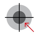
KEY TERMS:
Hot Spot: The brightest part of the pattern, usually in the center.
REQUIRED SUPPLIES:
• Tape or chalk to mark X and Y lines
• Corresponding tools for your vehicle’s aiming mechanism
NOTICE: If you are unsure about aiming your headlight, please see a professional. Failure to properly aim your headlights is a risk to other drives and could result in tickets or citations with local authorities. J.W. Speaker is not liable for any damage to the vehicle or light or any tickets/citations as a result of using these guidelines.
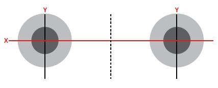
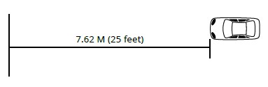
AIMING GUIDELINES:
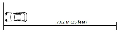
1. Park your vehicle close to a wall, in an area where there is at least 7.62 meters (25 feet) of space behind it (excluding the car length).
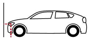
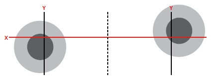
2. On the wall, draw a line from the ground to the approximate center point of the headlight. Repeat for the other headlight. This will create your Y axis lines.
3. Connect the center points between headlights in a straight line, using chalk or tape. This will create your X axis line. NOTE: Use a straight edge and a level to make sure this line is straight.
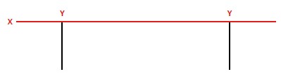
4. Extend your vertical, Y axis lines up approximately 3 feet. Your lines should match the diagram below, when looking at the lines straight on.

5. Reverse your vehicle in a straight line so that the front of the headlights are 7.62 meters (25 feet) back from the wall.
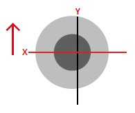
The goal of this sheet is to aim BOTH of your headlights so that the center of the Hot Spot is at the v of the horizontal X and vertical Y lines you have drawn. The following directions illustrate the process and proper aiming of headlights.
6. When you first turn on your vehicle after installing your headlights, the Alignment Points may be positioned differently than shown and will likely be aimed differently from each other.
7. Using the alignment mechanisms in your vehicle, adjust one headlight vertically until the alignment point is even with the X axis.
8. On the same headlight, adjust the same headlight horizontally until the alignment point is even with the Y axis.
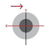
9. Repeat this process on the other headlight. Both headlights should match the diagram below, where the alignment point is even with the point where the X and Y axis crosses.