 FREE 1 to 3-Day Delivery on Orders $149+ Details
How to Install JMS BoostMAX Ecoboost Performance Booster on your F-150

Shop Parts in this Guide
Thank you for your purchase.
Please read the complete installation instructions or view the video
instructions on YouTube before attempting to install this product.
If not installed properly, BoostMAX will not function and may
be damaged. View install videos at http://www.jmschip.com/
boostmax-plug-and-play/
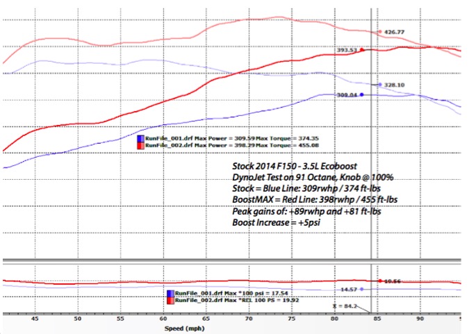
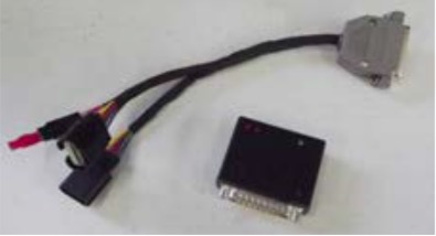
BoostMAX will increase the power output of your Ecoboost vehicle.
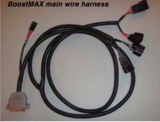
BoostMAX has been designed to be mounted with plastic zip ties
near the OEM ECU. The wiring harness plugs into two sensors on
the engine and then runs into the vehicle cabin through a drivers
side firewall hole and connects to the pedal sensor.
The concept behind BoostMAX:
• Add additional horsepower without reprogramming the ECU.
• BoostMAX connects to the MAP, TIP and Pedal Position sensors via a plug & play harness.
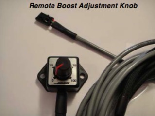
• Remote boost knob allows the user to add up to 5psi of additional boost (on the fly).
• 2.7L Ecoboost customers have reported gaining 50rwhp with the stock vehicle and BoostMAX (93 Octane).
• Add additional boost “on the fly” and when you want it.
• Use the remote boost knob to “dial-in” additional boost on the fly.
• Replace the remote boost knob with the Red Chip: 87 octane boost curve.
• Or remove the remote knob and red chip and enjoy the optimized 93 octane boost curve and more power!
• Simple to install, Plug and Play design that installs in just minutes.
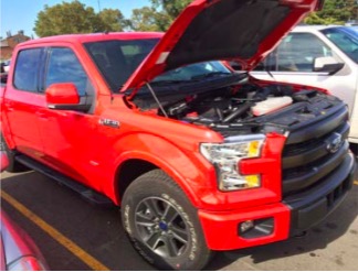
Step 1
• Ignition key off, remove key from ignition.
• Open the vehicle’s hood.
• Disconnect the negative battery terminal.
• Remove the engine oil fill cap
• Remove the plastic engine cover and set aside
Note: Two 10mm bolts hold the cover in place.
• Replace the engine oil fill cap
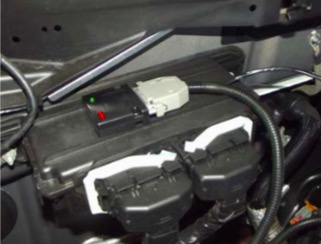
Step 2
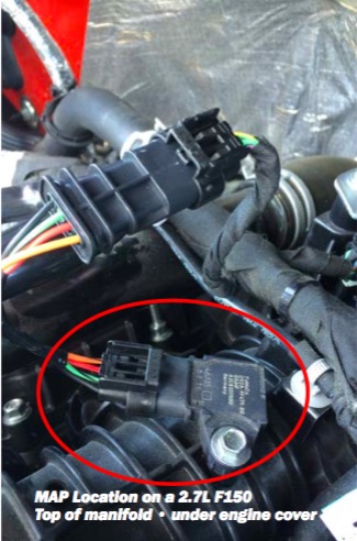
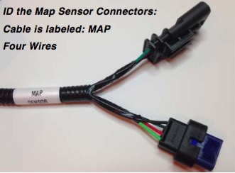
• Locate the MAP Sensor
The MAP Sensor is located on top of the black
plastic intake manifold, under the engine cover.
• Disconnect the OE MAP Sensor connector from
the MAP sensor.
• Connect the BoostMAX Wire Harness Labeled
“MAP Sensor” in-between the MAP Sensor and the
OE Connector.
• Use zip-ties to secure the MAP sensor wiring.
• Pictures show the Intake - MAP location on: 2.7L F150.
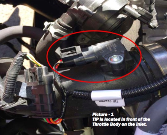
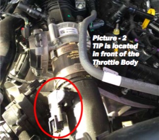
Step 3
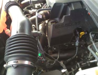
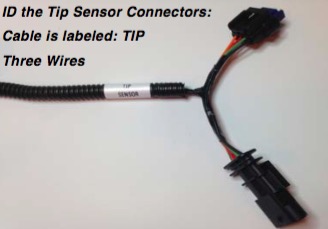
• Locate the TIP Sensor on the 2.7L Engine.
It is located on the air-inlet tube near the throttle
body on the discharge side of the Intercooler (see
pictures 1 & 2)
• Connect the BoostMAX Wire Harness Labeled
“TIP Sensor” in-between the TIP Sensor and the
OE Connector (picture 1).
• Use zip-ties to secure the TIP sensor wiring.
Be sure to secure the wire away from heat sources
and or moving engine parts.
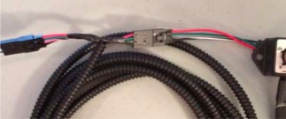
Step 4
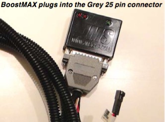
• Connect the BoostMAX Module to the DB-25
connector, secure the screws with the screwdriver.
• Route the BoostMAX wiring harness alongside the
factory ECU (located on the firewall).
• Use zip-ties to secure the BoostMAX Module near
the factory ECU.
• When routing the wiring, be sure to stay away from
high heat sources (exhaust).
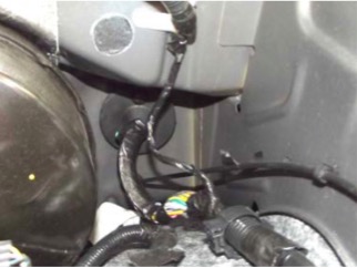
Step 5
• Route the flat four pin wire harness across the
back of the engine and pass it through the rubber
firewall grommet. Route the four pin wire through
the firewall grommet to the drivers side of the vehicle.
• Note: The firewall plug might be covered by insulation
on the inside. It may help to attach the
wire harness with tape to a stiff wire (coat hanger)
in order to fish it through the firewall opening (use
two people).
• Use zip-ties to secure the wiring.
Step 6
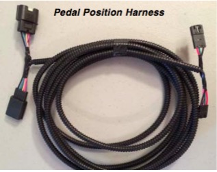
• Connect the Pedal Position Harness to the flat four
position main BoostMAX Harness (via flat four pin
connector, left side connector in the picture)
• Choose between connecting the Pedal Position
Harness to the Remote Boost Knob OR to the “87
Octane Red Chip”. (Right side connector in picture)
Note: In the picture the Pedal Position harness in
the center, the main harness plugs into the Pedal
Harness and then the Remote Knob Plugs into the
Pedal harness.
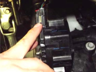
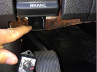
Step 7
• Locate the Accelerator Pedal Position Sensor
(Located on top of the Accelerator Pedal bracket)
• Disconnect the OE Pedal Position Sensor connector
from the Pedal Position sensor (pull the red tab
out and then press the black tab to release).
• Connect the BoostMAX Wire Harness Labeled
“Pedal Sensor” in-between the Pedal Position Sensor
and the OE Connector.
• Use zip-ties to secure the Pedal Position Sensor
wiring.
Step 8
• Route the Remote Boost Knob up and near the
center console. We recommend routing the cable
along side the center console (push the cable up
behind it) so you can adjust the knob “on the fly”.
• Use zip-ties to secure the Remote Boost Knob
wiring.
• Adjust the BoostKnob to the desired performance
level.
• Recommended knob settings: 87 octane = 50%,
91 octane = 90%, 93 octane = 100%.
Step 9
• Reconnect the negative battery terminal.
• Start and test the vehicle, it should function like
normal with additional WOT power. If the Ignition
Key is “ON” the Green LED on the BoostMAX will
illuminate ON.
• If the vehicle has a wrench light and no throttle: it
is due to disconnecting the Pedal Position Sensor.
• Turn the vehicle off, remove the key, wait 30 seconds
and restart the vehicle (the wrench light will
automatically clear itself on restart).
Enjoy the extra plug & play BoostMAX power.
Recommended Spark Plug and Spark Plug Gap for BoostMA X
This information applies to all 2011-2015 Ford F150 3.5L EcoBoost equipped trucks and 2010-
2015 Ford Taurus SHO 3.5L EcoBoost equipped cars. To eliminate the potential for ignition misfires commonly known as “spark blowout” at high RPM levels when running a JMS BoostMAX we recommend replacing the sparkplugs and setting the plug gaps as listed below in the chart.
Ecoboost 3.5L
| Year | Model | Plug OEM Part Number | Recommend GAP |
|---|---|---|---|
| 2011-2015 | F150 EcoBoost 3.5L | SP-534 | 0.030 in |
| 2010-2015 | Taurus EcoBoost 3.5L | SP-534 | 0.030 in |
Ecoboost 2.0L
This information applies to all 2013-2014 Ford Focus, Fusion, Taurus, Edge, Escape 2.0L EcoBoost equipped vehicles. To eliminate the potential for ignition misfires commonly known as “spark blowout” at high RPM levels when running a JMS BoostMAX we recommend replacing the sparkplugs and setting the plug gaps as listed below in the chart.
| Year | Model | Plug OEM Part Number | Recommend GAP |
|---|---|---|---|
| 2013-2015 | ALL - EcoBoost 2.0L | M-12405-20T (Ford Racing) | 0.028 in |
| 2013-2015 | ALL - EcoBoost 2.0L | ITV22 (Denso 5340) (Denso Iridium) | 0.028 in |
Please call us at 601-766-9424 for more information on Ecoboost 1.6L, 2.3L & 2.7L engines.
Note to Focus ST 2.0L Ecoboost owners
If you stay under high boost for longer than 15 seconds, your vehicle may go into overboost mode and the power/boost will be automatically pulled back by the factory ECU. This is a feature of your control system. To solve this issue, you will need a custom JMS ECU tune via an X4 stacked with your BoostMAX unit. The two units together provide the ultimate in performance for the Focus ST.
What is PedalMAX?
• Increases “off idle” throttle response
• Improve vehicle acceleration & torque
• Designed to be stacked with BoostMAX and a JMS Custom Tune File
• Simple to Install product that supports all Ford Gas & Diesel vehicles
• Does not void vehicle warranty
• Optional Single or Dual Remote Pedal Knob
• Sealed Enclosure
• Compact, Rugged design
• Plug & Play design
About JMS Chip & Performance
For more than 20 years, JMS Chip & Performance has been an industry leader in late model domestic and import vehicle tuning. JMS brand electronics components are some of the most technologically advanced in the automotive industry and feature innovative high quality engineering, materials and workmanship. The JMS technical center in Lucedale, MS is one of North America’s premier automotive and motorcycle tuning, manufacturing, and turn key automobile development facilities, producing numerous custom high performance vehicles each year. JMS is also a pioneer in domestic vehicle calibrations and highly regarded as a foremost expert in Ford, GM and Chrysler powertrain and drivetrain systems.
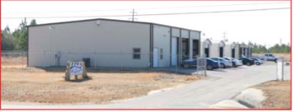
JMS Technical Center • Lucedale, MS
A state of the art facility that integrates custom and specialty vehicle manufacturing, race car production, electronics development and manufacturing, custom tuning and vehicle calibrations engineering, prototype development, and aftermarket component sales and distribution.

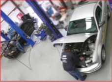
Light Vehicle Assembly
JMS produces countless custom or specialty vehicles ranging from contemporary late model domestic performance cars to full blown turn key race cars, each year. Our teams of professionals are experts in supercharging, turbocharging, engine assembly, chassis production, suspension upgrades, and specialty equipment integration.
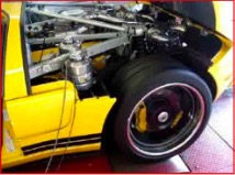
Custom ECU Calibration Engineering
Since 1993, JMS has been a pioneer and industry-leader in Ford vehicle calibrations and instrumental in helping to develop the modern custom tuning aftermarket. Our tech center’s tuning facility features two chassis dynamometers specifically for car and truck calibrations and engineering, and one motorcycle dyno to service the growing powersports market.
JMS Policies
How to order
Retail orders for JMS products can be placed through our website at: www.jmschip.com or by calling us factory direct at (601) 766-9424. JMS products can also be purchased through our network of warehouse distributors, dealers, jobbers, and installers. To locate a wholesaler or installer in your area, please contact us or use the dealer locator on our website.
Terms of Sale
JMS product orders are subject to our wholesale trade terms and conditions, which are located in the applicable price guide.
Shipping and Handling
JMS products are shipped F.O.B. Lucedale, MS via UPS or common freight carrier, and are subject to applicable shipping terms and charges. JMS does maintain a freight policy for warehouse distribution based on a minimum order qualification. Overseas order shipping via a common freight forwarding company or broker are the responsibility of the customer.
Pricing
JMS maintains a minimum advertised pricing policy to protect product value, and maintain consistent and fair distribution or retail pricing points. JMS places high value on its brand and product integrity.
Non-JMS Brand Parts
Aftermarket parts purchased from JMS are covered under the manufacturer’s warranty, and are not covered under the JMS manufactured products warranty.
Off-Road Notice and Terms & Conditions
JMS products are designed for Off-Road or Racing use only. JMS terms and conditions including: Pricing, specifications, warranty, and availability are subject to change without notice. Compliance with all federal, government, provincial, state or local laws are the responsibility of the customer or end-user. All claims of product performance are based on controlled testing conditions and real-time data, and results may vary based on your application or use. JMS shall not be liable for any fines or violations resulting from product use or installation.
Service or Repair:
Please contact JMS @ 601-766-9424 for a Return Authorization. All service returns should be sent freight pre-paid to: JMS SERVICE, 3247 HWY 63 S, Lucedale, MS 39452. The Return Authorization Number should be clearly written on the outside of the box, and in a letter that is included in the box. The letter should also list your contact phone number and a clear explanation of the exact problem.
JMS Warr anty & Contact information
JMS warr ants to the original purchaser the following:
Your JMS Product will be free from defects in materials and workmanship for a period of twelve months from the original purchase date. The warranty only covers the product itself and not the cost of removal and re-installation of the product. JMS may extend the limited warranty on a case by case basis, based on the circumstances of the warranty claim. JMS products are designed exclusively for use in racing applications. JMS products that are not installed according to the supplied instructions,
may not be covered by warranty.
Specific conditions that will VOID the product warr anty:
If the product case has been opened or the product has been modified or repaired.
If the product was not installed or used correctly.
If the product has been tampered with by: negligence, misuse or accident.
If the product is returned without explanation of the problem or Return Authorization.
Contact JMS @ 601-766-9424 for a Return Authorization Number:
All warranty returns should be returned freight pre-paid and should include inside of the box: Proof of Purchase and a Letter that contains both the Return Authorization Number and a Clear Explanation of the EXACT problem. The Return Authorization Number should also be clearly written on the outside of the box.
Send all returns to:
JMS Returns, 3247 HWY 63 S, Lucedale, MS 39452
JMS Chip & Performance LLC is not liable for any and all consequential damages arising from the breach of any implied or written warranty in regards to the sale of this product, in excess of the purchase price.
Technical Support & Contact Information:
JMS 3247 Hwy 63 S, Lucedale, MS 39452
601-766-9424
Technical Support Hours: Monday - Friday 9:00am - 5:00pm (Central Standard Time)
Configuration and installation videos are available online: www.youtube.com/jmschip
If you have any questions, please contact JMS technical support via email: [email protected]
Follow JMS on FaceBook: www.facebook.com/jmschips
JMS on YouTube: www.youtube.com/jmschip
JMS Website: www.jmschip.com
JMS on Instagram: @jmschip

