FREE 1 to 3-Day Delivery on Orders $149+ Details
How to Install FOX 3.0 Factory Series Bypass Reservoir Shock w/ QAB Adjuster - Rear on your F-150

Shop Parts in this Guide
INSTRUCTIONS - FRONT
Medium-strength thread-lock (blue Loctite®) is recommended on all bolts.
1. Please read the INSTALLATION GUIDELINES for instructions on how to properly lift and secure the vehicle.
2. Record the front vehicle ride height to ensure proper lift is attained after kit is installed. You will be able to make preload adjustments if needed once the shock assembly is installed. (Spanner wrench required) READ INSTALLATION GUIDELINES ON HOW TO PROPERLY ADJUST PRELOAD
3. Remove front wheel.
4. Remove the (3) top nuts that secure the stock shock assembly to the vehicle. DO NOT remove center nut; doing so will release the spring from the stock assembly and could result in SERIOUS INJURY or DEATH!
5. Remove the (1) bolt connecting the shock to the lower control arm. DO NOT discard bolt and nut as it will be used with your new FOX coil-over assembly.
6. Disconnect outer tie rod end at the knuckle for removal/installation clearance.
7. Disconnect upper ball joint at the knuckle for removal/installation clearance. CAUTION DO NOT stretch the brake line or the wires that run to the steering knuckle.
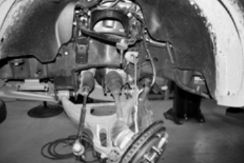
8. Swing the knuckle towards the rear of the vehicle (Fig.1) leaving removal/ installation clearance.
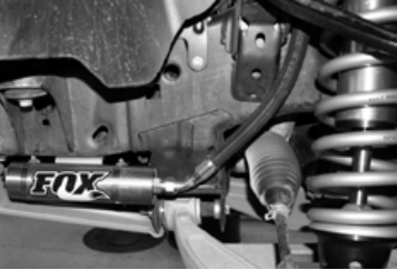
9. Remove the stock shock assembly. Be careful not to damage any brake lines or electrical wires. 10. Install the new coil-over assembly making sure that the reservoir hose is facing towards the front of the vehicle (Fig. 2). Connect the top shock hat to the vehicle using the bolts and washers provided. Tighten to 24 ft*lbs.
11. Connect the shock to the lower control arm utilizing the stock bolt and nut. Torque to 406 ft*lbs.
12. Reconnect the upper ball joint at the spindle. Torque to 85 ft*lbs.
13. Reconnect the outer tie rod ends and torque to 85 ft*lbs. Reconnect any lines or wires you may have loosened.
14. Install the reservoir bracket with the supplied washers and nuts to the underside of the frame rails in front of the suspension. Drop the bolt bracket into the frame rail and use a pick or similar tool to help drop the bolts through the holes in the frame rail. (Some earlier Raptors do not have these holes in the frame rails. If so, proceed to step 16.)
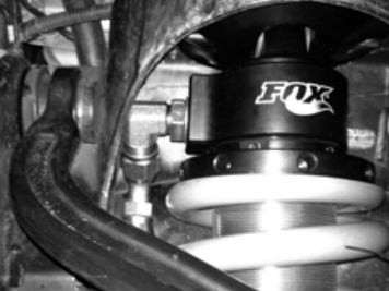
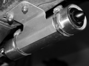
15. Using two supplied clamps, mount the reservoir to the brackets making sure to check that the hose will not rub on any frame or suspension components (Fig. 3). Utilize the slots in the bracket to locate the clamps. Do not feed the clamps through the slots in the brackets (Fig. 4).
16. For Raptors that are missing the reservoir bracket mounting holes in the frame rails, mount the reservoir to the bracket using the two supplied clamps.
17. Holding the bracket and reservoir in the proper position making sure to check that the hose will not rub on any frame or suspension components (Fig. 3). Mark and drill the holes for the mounting bolts (Center punch, 3/8” bit, and power drill required). Now complete step 14.
18. Check that the suspension has proper clearance by steering completely in both directions.
19. Reinstall the front wheel and torque the lug nuts to 150 ft*lbs.
20.Set vehicle back on the ground and drive it back and forth several feet to allow the suspension to settle. Now measure ride height and make adjustments if necessary. READ INSTALLATION GUIDELINES ON HOW TO PROPERLY ADJUST PRELOAD
21. It is highly recommended that you have your wheel alignment checked.
INSTRUCTIONS - REAR
Medium-strength thread-lock (blue Loctite®) is recommended on all bolts.
1. Please read the INSTALLATION GUIDELINES for instructions on how to properly lift and secure the vehicle.
2. Remove rear wheel.
3. Remove the stock shocks.
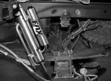
4. Utilizing the stock bolts and nuts, install the new bypass shock with the reservoir facing towards the axle, and the bypass tubes facing towards the tires (Fig. 5). Torque to 66 ft*lbs. Fig. 5: Driver side
5. Reinstall rear wheel and torque the lug nuts to 150 ft*lbs.