FREE 1 to 3-Day Delivery on Orders $149+ Details
How to Install Flowmaster Force II Cat-Back Exhaust - Single Side Exit on your F-150

Shop Parts in this Guide
Removal:
1) Raise the vehicle up on a hoist or rack to working height. If you do not have access to a hoist or rack, raise the vehicle and support securely with jack stands.
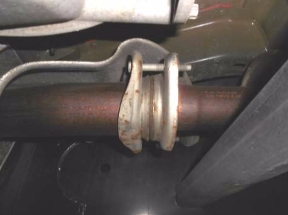
2) Begin by applying a lubricant to each of the rubber exhaust isolators as well as the two front flange bolts. This will make the removal and installation process much easier.
3) Support the muffler with a stand and remove the two bolts at the front flange connection. Now, with the help of an assistant, slide the exhaust system to the rear to disengage the hangers on the exhaust from the rubber mounts on the vehicle. Once free, the assembly can be removed by working it forward over the rear axle (If you are working on the ground it may be easier to cut the tailpipe off at the rear of the muffler to simplify removal).
Installation:
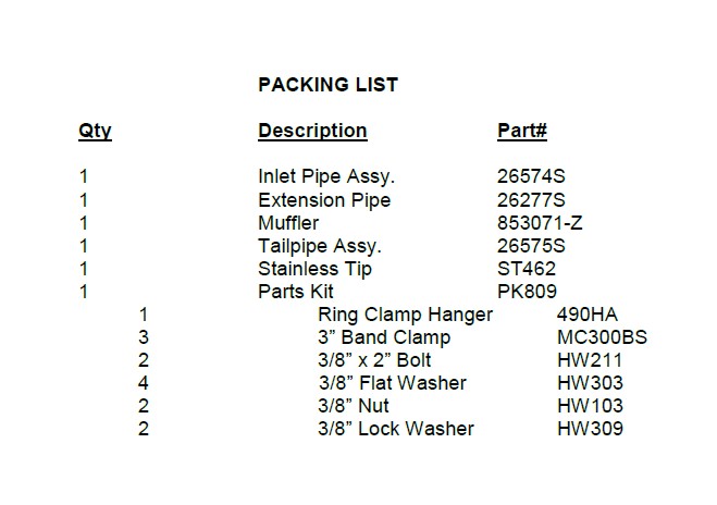
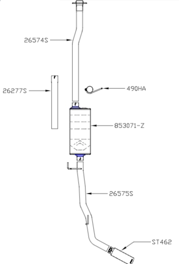
1) Based on production variations this is a list of cab designs, bed lengths and wheel bases that outlines the requirements for the front inlet pipe. Please follow the instructions for your particular wheelbase listed below. Double check all measurements before cutting your inlet pipe:
141” WB - Regular Cab / 8’ Bed - Trim 4” off of inlet pipe #26574S (do not use #26277S)
145” WB - Super Crew / 5.5’ Bed - Use inlet pipe #26574S with no modifications (do not use #26277S)
145” WB - Super Cab / 6.5’ Bed - Use inlet pipe #26574S with no modifications (do not use #26277S)
157” WB - Super Crew /6.5’ Bed - Trim 6” off of extension pipe #26277S and use with inlet pipe #26574S
163” WB - Super Cab / 8’ Bed - Use inlet pipe #26574S and extension pipe #26277S with no modifications.
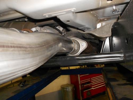
2) Place the inlet pipe onto the back of the existing OEM head pipe and fasten using the 3/8” x 2.00” bolts, nuts and washers provided in the hardware kit. Tighten just enough to hold in place, but still allow for adjustment.
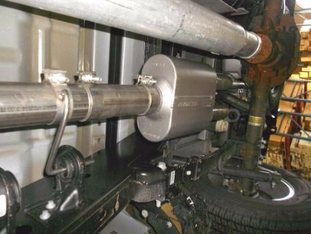
3) Slide the inlet hanger #490HA over the back of the inlet pipe and insert the hanger into the factory rubber mount. Do not tighten this clamp yet. If required, place the extension pipe #26277S onto the back of the inlet pipe. Then place the inlet of
the muffler onto the back of inlet pipe and support with a stand. Level the muffler and tighten the clamp at the inlet enough to hold, but still allow for adjustment.
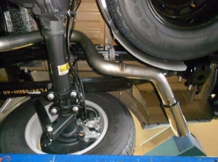
4) Install a provided clamp onto the muffler outlet. Then place tailpipe #26575S into position over the axle and into the muffler outlet while also connecting the hangers on the pipe to the rubber mounts on the vehicle. Tighten the band clamp enough to hold, but still allow for adjustment.
5) Place the stainless tip #ST462 onto the end of the tailpipe and tighten the pinch bolt just enough to hold in position. Rotate the tip to the desired location. The final adjustment of the tip is best left to the final step, with the vehicle on the ground so that you can get a good view.
6) Now go back and adjust the position of all pipes and muffler to provide a satisfactory fit. A minimum of 3/4” clearance around all parts of the system must be maintained; while keeping suspension travel and vibration in mind. After adjustments have been made, you may now securely tighten all clamps, including the front hanger/clamp assembly.