FREE 1 to 3-Day Delivery on Orders $149+ Details
How to Install Flowmaster Force II Aluminized Steel Cat-Back Exhaust - Split Side/Rear Exit

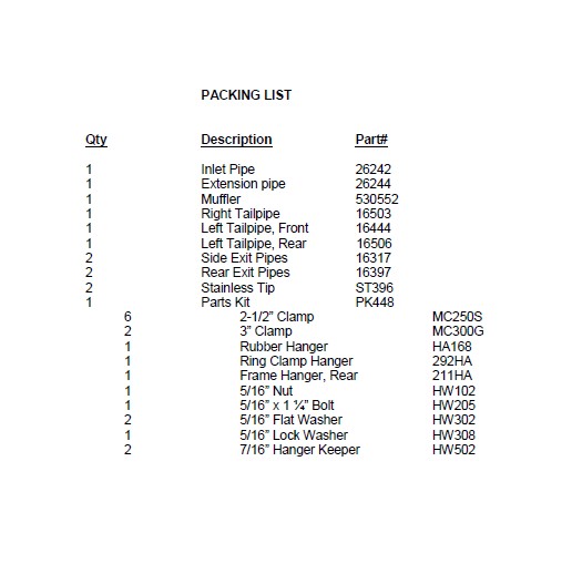
Shop Parts in this Guide
Removal:
1) Disconnect the negative side of the battery cable. Raise the vehicle up on a hoist or rack to working height. If you do not have access to a hoist or rack raise the vehicle and support securely with jack stands.
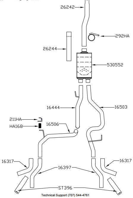
2) Using a hacksaw or sawsall, cut the tailpipe off where it exits the muffler. Remove the muffler and set aside.
3) Support the muffler with a stand. Separate the three rubber hangers on the muffler and tailpipe from the rubber mounts on the vehicle. (A lubricant of some kind will make this easier.)
4) Remove the clamp that secures the factory inlet pipe to the converter Y-pipe. Remove the inlet pipe/muffler assembly and set aside.
Installation:
1) Before installing anything, prep the clamps supplied in the hardware kit by removing the nuts, and applying a thick lubricant such as white grease or anti-seize to the threads.
2) Based on production variations this is a list of cab designs, bed lengths and wheel bases to cut your new inlet pipe #26242 to fit your application. Double check all measurements before cutting your inlet pipe:
Regular Cab
6.5’ Bed – Trim 19.50” off the rear of the inlet pipe.
8.0’ Bed – Trim 1.0” off the rear of the inlet pipe.
Super Cab
5.5’ Bed – Trim 13.0” off the rear of the pipe.
6.5’ Bed – Trim 1.0” off the rear of the pipe.
8.0’ Bed – No trim on #26242, add extension to pipe #26244 and trim off 2.25”.
Super Crew
5.5’ Bed – Trim 7.0” off the rear of inlet pipe.
6.5’ Bed – No trim on #26242, add extension to pipe #26244 and trim off 14.75”.
3) Slide a 2 1/2" clamp #MC250S over the reduced end of the inlet pipe. Place the inlet pipe onto the back of the existing OEM head pipe (by lining up the notch). Tighten enough to hold in place, but still allow for adjustment.
4) Slide the inlet hanger #292HA over the back of the inlet pipe and insert the hanger into the factory rubber mount. Tighten both clamps enough to hold, but still allow for adjustment.
5) Mount the left hanger bracket #211HA to the frame on the driver’s side of the vehicle. There are factory holes (one round, one square) on the bottom of the frame next to spare tire. Place the 5/16” bolt and flat washer up into the square hole and back down through the round hole. Using a flexible head magnet to help guide the bolt makes this process much easier. Now place the bracket in position and install a flat washer, lock washer and nut. Using two 1/2” wrenches tighten firmly (do not overtighten). Once the hanger bracket is secured, slide on rubber hanger #HA168.
6) Slide a 2 1/2" clamp #MC250S onto each muffler outlet neck. Place the right side tailpipe #16503 into position over the axle and into the right side muffler outlet. Place the tailpipe hanger rod into the factory rubber mount. Tighten the clamp enough to hold, but still allow for adjustment.
7) Place the front section of the left side tailpipe #16444 into the left side of the muffler outlet and insert hanger welded to pipe into the factory rubber mount. Tighten the clamp enough to hold, but still allow for adjustment. Place another 2 1/2” clamp onto the rear (expanded) end of the pipe and tighten enough to hold in place, but still allow for adjustment.
8) Place the left rear tailpipe section #16506 into the expanded connection of the front section (#16444). Connect the hanger rod to the rubber mount installed in Step 5. Tighten the clamp down enough to hold the pipe in place, but still allow for adjustment.
9) Slide either the side exit pipe #16317 or rear exit pipe #16397 onto the ends of both over axle pipes. Place a 2 1/2” clamp onto these slip-fit connections and tighten enough to hold, but still allow for adjustment. Place the two stainless tips #ST396 onto the exit pipes and tighten the hose clamps enough to hold, but still allow for adjustment. Rotate the exit pipe and tip to the desired distance from the fender or bumper so that the angle cut on the tips are in the desired location. We highly
recommend tack welding the tip to the exit pipe to prevent possible slippage and loss of the tip.
10) Adjust the position of all pipes and muffler to provide a satisfactory fit. A minimum of 3/4” clearance around all parts of the system must be maintained; while also keeping suspension travel and vibration in mind. After adjustments have been made, you may now securely tighten all clamps.
11) After the system is secure, slide the 7/16” hanger keeper onto the left tailpipe hangers. This keeper will prevent the hanger rods from slipping out of the rubber mount.
12) For a cleaner appearance and more secure installation, we highly recommend welding all slipfit connections. If you live in a geographical area that has harsh winters or sees a great deal of precipitation, the use of high temperature paint over the welded areas can help to prevent surface rust and premature corrosion.