FREE 1 to 3-Day Delivery on Orders $149+ Details
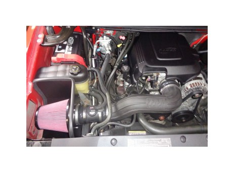
How to Install Flowmaster Delta Force Cold Air Intake (07-08 4.8L Silverado 1500) on your Chevy Silverado

Shop Parts in this Guide
REVIEW THE INSTRUCTIONS AND VERIFY THE KIT CONTENTS:
1. Please take a moment to read and understand these instructions before installing your Flowmaster cold air intake kit.
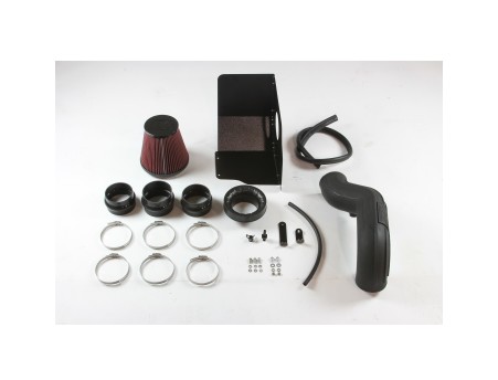
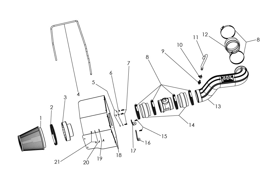
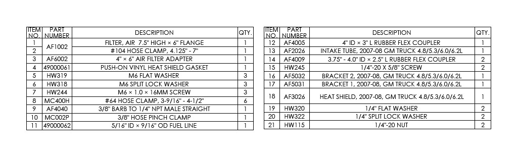
2. Use the parts drawing and list (front page) to verify your kit’s contents.
In the unlikely event that any parts are missing, please contact FLOWMASTER Technical Support for replacements.
To simplify assembly and avoid cross-threading fasteners , identify and separate the ¼-20 screws, item (15) (used with nuts (21)), and the M6 screws (7) (used with filter adapter (3)).
REMOVE THE FACTORY AIR INTAKE SYSTEM:
NOTES
• We highly recommend that you retain all factory air intake system parts.
• Please refer to vehicle manufacturer’s recommendations regarding removal of factory components.
• Disconnecting the negative battery cable erases pre-programmed electronic memories. Write down all memory settings before disconnecting the negative battery cable. Some radios will require an anti-theft code to be entered after the battery is reconnected. The anti-theft code is typically supplied with your owner’s manual. In the event your vehicle’s anti-theft code cannot be recovered, contact an authorized dealership to obtain your vehicle’s anti-theft code.
3. Turn off the vehicle’s ignition and disconnect the negative battery cable.
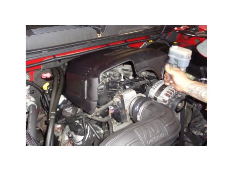
4. Remove the engine cover by firmly lifting it straight up to release it from its friction clips.
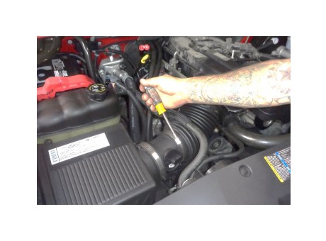
5. Use a flat-tip screwdriver to separate the coolant hose clamp from the intake duct, then remove the clamp from the hose.
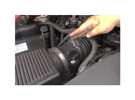
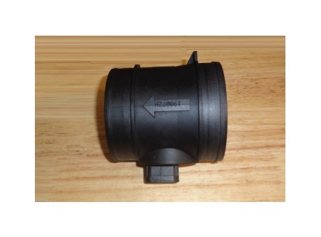
6. Disconnect the electrical plug from the Mass Airflow (MAF) sensor.
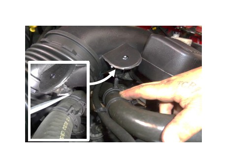
7. Loosen the hose clamp securing the air intake duct to the throttle body..
8. Loosen the hose clamp securing the air intake duct to the MAF sensor, then disconnect the intake duct from the MAF sensor.
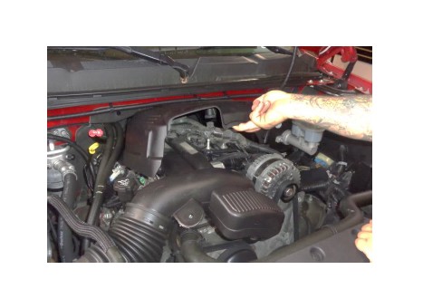
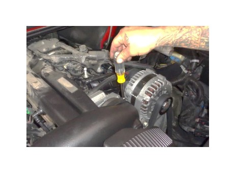
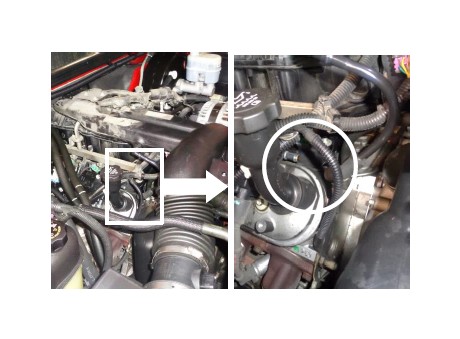
9. Carefully pull the breather hose off the breather line (just inboard of the oil filler neck – shown disconnected).
10. Lift the intake duct resonating chamber straight up, just enough to release it from its friction clip.
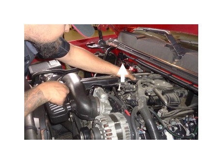
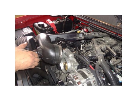
11. Disconnect the intake duct from the throttle body, and remove the duct from the vehicle.
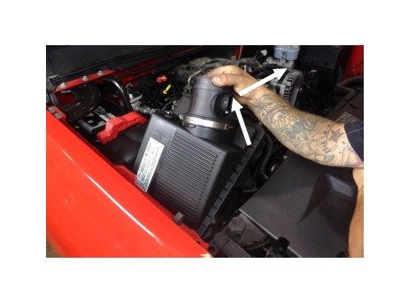
12. Remove the assembled airbox and MAF sensor by grasping the sensor and lifting straight up (to release the airbox mount pins from their rubber grommets), then sliding the airbox inboard to release it from its shelf.
13. Remove the MAF sensor from the airbox. CAUTION: The sensor is delicate! Handle it with care, and place it in a safe location until reinstallation.
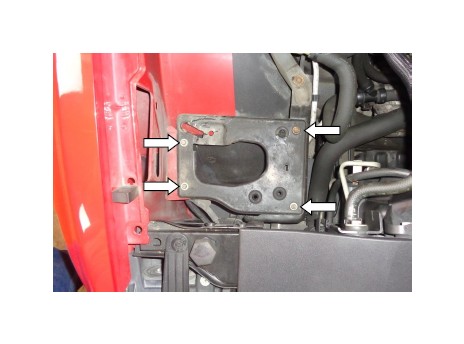
14. Remove the airbox shelf mount bolts, and remove the shelf. Retain the bolts for installation of the heat shield at Step 20. NOTE: During removal of airbox shelf mount bolts, if there are any differences in bolt length, note each bolt’s location, in order to maintain proper hardware clearance at reinstallation.
ASSEMBLE AND INSTALL YOUR FLOWMASTER COLD AIR INTAKE SYSTEM:
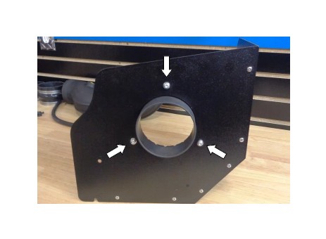
15. Assemble air filter adapter (3) to heat shield (18) using M6 screws (7), lock washers (6) and flat washers (5).
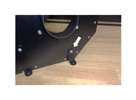
16. Attach long bracket (16) to heat shield using ¼-20 screw (15) (against the bracket) and nut (21), lock washer (20) and flat washer (19) (against the heat shield). Do not fully tighten hardware at this time.
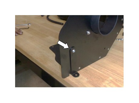
17. Attach short bracket (17) to heat shield using ¼-20 screw (15) (against the bracket) and nut (21), lock washer (20) and flat washer (19) (against the heat shield). Do not fully tighten hardware at this time.
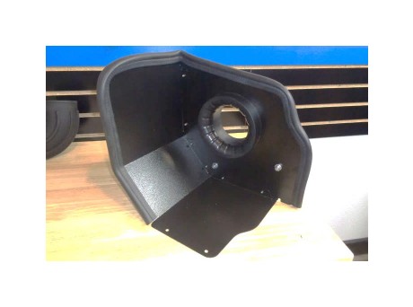
18. Attach gasket (4) to heat shield as shown. Starting at one end, firmly press the gasket onto the edge, gradually working around the heat shield. When you arrive at the ending point, use metal-cutting shears to trim the gasket to length.
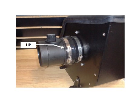
19. Slip two hose clamps (8) onto a 3¾" - 4" coupler (14). Push the coupler’s 4" end onto the air filter adapter, all the way against the heat shield, and tighten the clamp. Orient the MAF sensor so that the airflow arrow points away from the coupler, and push the sensor fully into the coupler, so that its lip touches the coupler, then tighten the clamp.
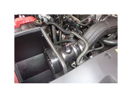
20. Place the assembled heat shield in the vehicle, and secure it with the 4 bolts retained at Step 13. NOTE: To maintain hardware clearances, use the correct length bolt at each location (as noted in Step 14). Then tighten the heat shield bracket screws.
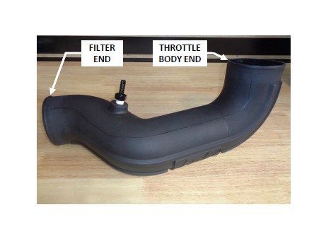
21. Apply 2 wraps of nylon thread tape to threads of 3/8" barbed fitting (9), and install it in the intake tube (13). Note the Filter and Throttle Body ends of the tube (for the next two steps).
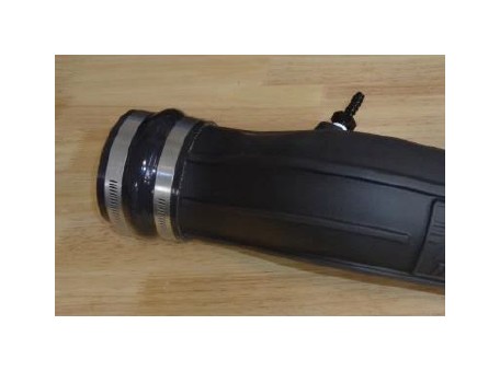
22. Slip two hose clamps (8) onto the other 3¾" - 4" coupler (14). Install the 4" end of the coupler on the Filter end of the intake tube, and snug (but do not yet tighten) the hose clamps.
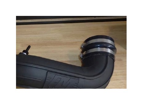
23. Slip the last two hose clamps (8) onto the 4" coupler (12), then install the coupler on the throttle-body end of the intake tube. Snug (but do not yet tighten) the clamps.
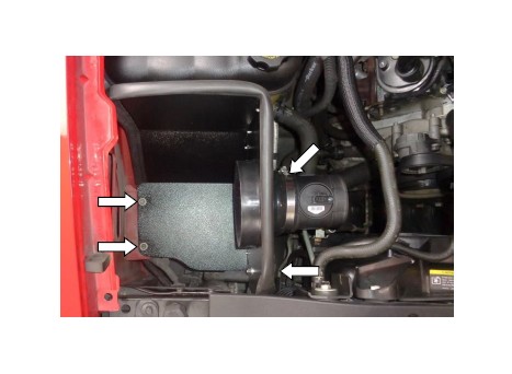
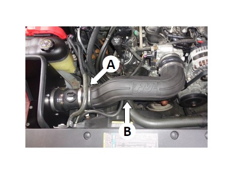
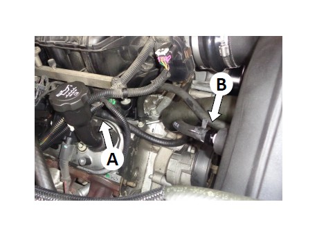
24. Install the intake tube in the vehicle. The tube will pass under the coolant overflow line (A), and over the two radiator lines (B).
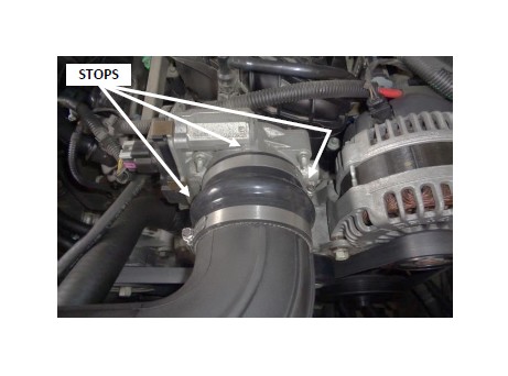
25. Push coupling (12) up against the stops on the throttle body opening and tighten the throttle body clamp. (Do not yet tighten the tube clamp.)
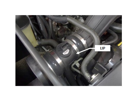
26. Push coupling (14) up against the lip on the MAF sensor and tighten the sensor clamp. (Do not yet tighten the tube clamp.)
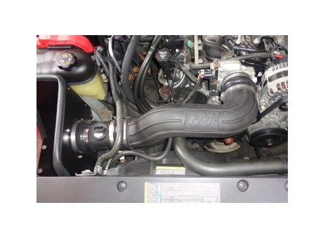
27. Adjust the intake tube as necessary to avoid contact with surrounding components (such as the radiator hoses). When the tube is aligned as desired, tighten the two tube clamps.
28. Push one end of hose (11) onto engine PCV tube (A). Cut the hose to length and secure it to the barbed fitting (B) with the pinch clamp (10).
29. Plug the MAF sensor lead into the sensor until it clicks, then verify the connection is secure.
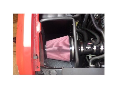
30. Slip clamp (2) onto air filter (1), install filter on filter adapter, and tighten clamp.
31. Install the engine cover by aligning it with its mount posts, then snapping it into place.
Congratulations, the installation of your FLOWMASTER cold air intake kit is now complete!