 FREE 1 to 3-Day Delivery on Orders $149+ Details
How to Install Firestone Ride-Rite Air Helper Springs on your F-150
STEP 1- PREPARE THE VEHICLE
With the vehicle on a solid, level swface, chock the front wheels. Raise the vehicle by the rear axfe and set on jack stan·ds rated for your vehicles weight. Remove the real wheels. Remove the jounce bumpers from the under side of the frame rail. The jounce bumper will not be re-used with the kit, but the bolt will be re-used.
STEP 2-ATTACH THE UPPER BRACKET
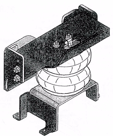
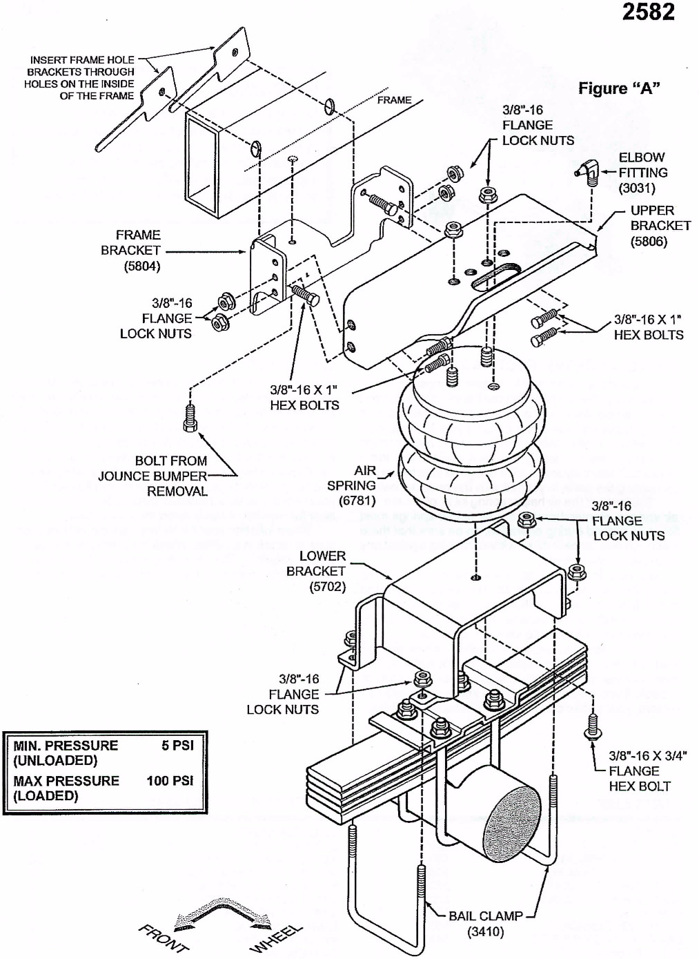
Select one air helper spring and one upper bracket from your kit. Insert the studs of the c)ir spring into the mounting holes of the upper bracket. Make sure the air inlet is visible through the large access hole. Fasten the upper bracket to the air spring using the 3/8"-16 flange nuts, see Figure "A". Install the elbow fitting into the air spring through the large access hole in the upper bracket. Tighten the air fitting securely to engage the orange thread sealant. Position the fitting to point to the anticipated location of the air inflation valves.
STEP3A-ATTACH THE LOWER BRACKET (4WD)
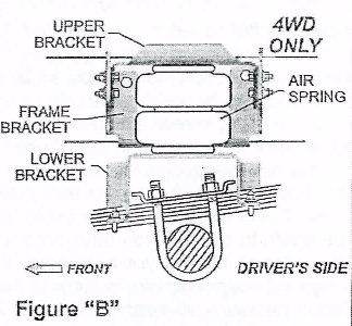
Select the left lower bracket and fasten it to the air spring with a 3/8"-16 x 3/4" flange bolt (finger tight). Figure "B";
STEP 38-ATTACH THE LOWER BRACKET (2WD)
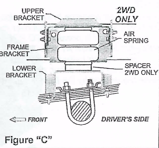
Select the left lower bracket and spacer and attach thein to the air spring with a 3/8"-16 x 2" flange hex bolt {finger tight). Open end of the spacer should mount towards lower bracket. See Figure "C".
STEP 4-ATTACH THE FRAME BRACKET TO THE FRAME
Attach the left frame bracketto the bottom of the frame reusing the jounce bumper bolt in the hole from the jounce bumper removal. Next, insert the 3/8"-16 x 1" hex head bolts through the left frame bracket and into the holes on the outsf de of the frame. Secure with framehole brackets inserted through the. hole on the inside of the frame. See Figure "A". DO NOT OVER TIGHTEN! 20 FT/LBS Max.
STEP 5- INSTALLING THE ASSEMBLY TO THE VEHICLE
Place the assembly on the leaf stack over the spring retainer and align the holes in the upper bracket with the lower four holes in the left frame bracket.Install fou,, 3/8" x 1" hex head bolts and fasten using 3/8"-16 flange nuts.Secure the left lower bracket to the leaf stack using bail clamps and 3/8"-16 flange nuts. Once aligned, tighten the bolt holding the bottom of the air spring to the lower bracket. See Figures "A", "B" & "C".
STEP 6-/NSTALLATION TO THE PASSENGER'S SIDE ASSEMBLY
Reverse any orientations when assembling and installing the right, or passenger, side of the vehicle. ·
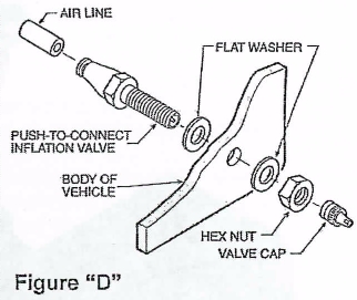
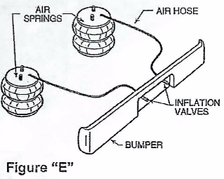
STEP 7-INSTALL THE AIR LINE AND THE INFLATION VALVE
Uncoil the air line tubing and cut it into two equal lengths. DO NOT FOLD OR KINK THE TUBING. Try to make the cut as square as possible. Insert one end of the tubing into the elbow fitting installed in the top of the air helper spring. Push the tubing into the fitting as far as possible. Select a location on the vehicle for the air inflation valves. The location can be on the bumper or the body of the vehicle, as long as it is in a protected location so the valve will not be damaged, but maintain accessibility for the air chuck, see Figure "E". Drill a 5/16" hole arid install the air inflation valve using two 5/16" flat washers per valve as supports, see Figure "D". Run the tubing from the air helper spring to the inflation valve, routing it to avoid direct heat from the engine, exhaust pipe, and away from sharp edges. Thermal sleeves have been provided for these conditions. If a thermal sleeve is required simply slide the sleeve over the air line tubing to the location requiring protection. The air line tubing should not be bent or curved sharply as it may buckle. Secure the tubing in place with the nylon ties provided. Push the end of the air line tubing into the inflation valve as illustrated, see Figure "D"
STEP 8- CHECK THE AIR SYSTEM
Once the inflation valves are installed, inflate the air helper springs to 70 psi and check the fittings for air leaks with an applied solution of soap and water. If a leak is detected at a tubing connection then check to make sure that the tube is cut as square as possible and that it is pushed completely into the fitting. The tubing can easily be removed from the fittings by pushing the collar towards the body ofthe fitting and then pulling out the tube. If a leak is detected where the fitting screws into the spring, screw the fitting into the air spring until the leak stops. Reinstall the tubing and reinflate the air springs and check for leaks as noted above.
This now completes the installation, Install the wheels and torque the lug nuts to the manufacturer's specifications. Raise the vehicle by the rear axle and remove the jack stands and lower the vehicle back onto the ground. Re-attach the negative battery cable and remove the wheel chocks from the wheels. Before proceeding, check once again to be sure you have proper clearance around the air springs. With a load on your vehicle and the air helper springs inflated, you must have at least 1/2" clearance around the air springs. As a general rule, the air helper springs will support approximately 40 lbs. of load for each psi of inflation pressure (per pair). For example, 50 psi of inflation pressure will support a load of 2000 lbs. per pair of air helper springs. FOR BEST RIDE use only enough air pressure in the air helper springs to level the vehicle when viewed from the side (front to rear). This amount will vary depending on the load, location of load, condition of existing suspension and personal preference.
NOTE:
Too much air pressure in the air helper springs will result in a firmer ride, while too little air pressure will allow the air helper spring to bottom out over rough conditions. Too little sirpressure will also not provide the improvement inhandling that is possible. TO PREVENT POSSIBLE DAMAGE MAINTAIN A MINIMUM OF 5 psi IN THE AIR HELPER SPRINGS AT ALL TIMES.
Once the air helper springs are installed, it Js recommended that the vehicle not be lifted by the frame, as over-extension may occur; resulting in damage. to the air helper springs. However; should it become necessary to raise the vehicle by the frame, deflate both air helper springs completely.

