 FREE 1 to 3-Day Delivery on Orders $149+ Details
How to Install Firestone Light Duty Air Command Dual-Path Air Control System - Wireless Gauge
Tools Required
- 3/16" DRILL BIT
- WIRE CRIMPER/STRIPPER
- PHILLIPS SCREW DRIVER
- 9/16" WRENCH
- (2) 7/16" WRENCHES OR SOCKETS
- POWER DRILL
- ELECTRICAL TAPE
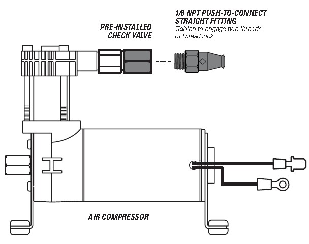
1. PREPARE THE AIR COMPRESSOR
Note that the Air Compressor can be mounted facing any direction.
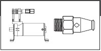
1 Install 1/8 NPT Push-to- Connect Straight Fitting on the Check Valve.
2. DRILL HOLES FOR AIR COMPRESSOR AND ECU
CHECK SURROUNDING AREA AND BACK SIDE OF MOUNTING LOCATION TO AVOID DRILLING INTO EXISTING LINES OR WIRING.
IF YOU ARE USING THE OPTIONAL FIRESTONE AIR ACCESSORY MOUNTING KIT, SKIP THIS STEP AND REFER TO THE MOUNTING KIT’S INSTRUCTIONS.
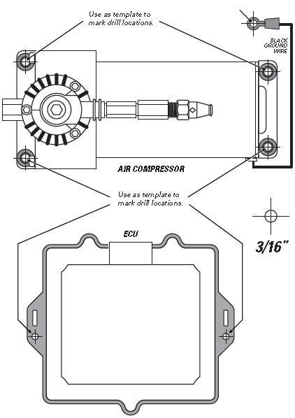
1. Using the Air Compressor and ECU as templates, mark drill locations as shown with a punch or marking tool.
2. Mark Air Compressor ground wire fastening location within reach of the ground wire ring terminal.
3. Drill 3/16” diameter holes. Remove any burrs and debris from drill holes.
ASSURE THAT YOU INSTALL THE AIR COMPRESSOR AND ECU CLOSE ENOUGH SO THE CONNECTORS ON THE WIRE HARNESS WILL REACH THEM BOTH.
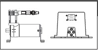
3. INSTALL THE AIR COMPRESSOR AND ECU
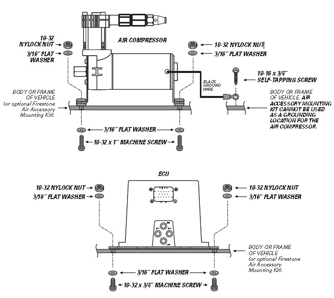
DO NOT OVER TIGHTEN MOUNTING BOLTS AND NUTS ON THE AIR COMPRESSOR. TOO MUCH TORQUE CAN CRUSH THE BRASS INSERTS AND RUBBER ISOLATORS.
1. Mount the Air Compressor to the drill hole location using the supplied fasteners. DO NOT OVER TIGHTEN.
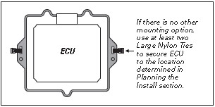
2. Mount the ECU to the drill hole location using the supplied fasteners.
3. Mount the black ground wire ring terminal using the supplied fasteners. Assure that the ring terminal makes a solid contact with bare metal for a proper ground.
4. INSTALL THE WIRE HARNESS
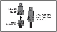
1. Determine a suitable location to mount the Sealed Relay, assuring it will be within reach of the relay connector on the Wire Harness.
2. Securely fasten the Sealed Relay as shown.
3. Route the Wire Harness in the most protected manner possible, and securely make all connections as shown.

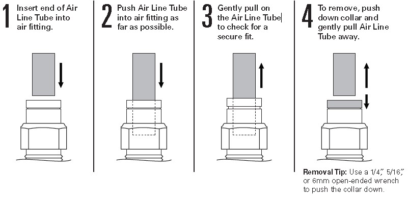
5. INSTALL AIR LINE TUBES
EXHAUST ALL AIR FROM THE SYSTEM PRIOR TO RELEASING AIR TUBES FROM AIR FITTINGS.
1. Route the Air Line Tube from 1/8 NPT Push-to-Connect Straight Fitting on the top of the Air Compressor to the Supply (SUP) air fitting on the ECU, leaving room to secure it safely. Use the guidelines on page 4 for proper Push-to-Connect Straight Fitting install.
2. Repeat Steps 1 to route Air Line Tube from the ECU to the Air Springs. Use the AS-1 and AS-2 air fittings on the ECU.
3. If desired, install Air Line Tube to the Exhaust (EXH) air fitting to reduce exhaust noise and prevent dirt from clogging the port (recommended for off-road or dirty environments). Do not exceed 16" of Air Line Tube, and secure it so the end turns to the ground.
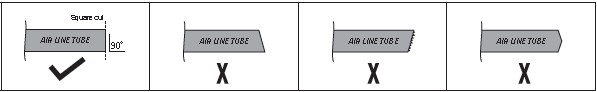
DO Make sure the cut is as square as possible. Use a tube cutter or very sharp utility knife.
DON’T Fold or kink the Air Line Tube. Cut the Air Line Tube at an angle. Use pliers, scissors, snips, saws, or side cutters.
PROPER AND IMPROPER CUTS IN THE AIR LINE TUBE
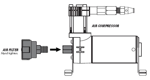
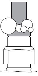
6. INSTALL THE AIR FILTER
1 Install the Air Filter by threading it onto the Air Compressor as shown.
2 Periodically check the Air Filter during operation. When the Air Filter is dirty and needs to be replaced, contact an Authorized Firestone dealer to purchase a new one.
FILTER LIFE WILL VARY BASED ON ENVIRONMENTAL CONDITIONS. PROTECT THE AIR COMPRESSOR BY CHANGING THE AIR FILTER MORE FREQUENTLY IN DUSTY CONDITIONS.
7. CLEAN UP INSTALLATION
1. Clean up the installation using supplied Nylon Ties, and return all factory parts and materials to operative state.
USING SUPPLIED NYLON TIES, SECURE ALL WIRING AND AIR LINE TUBE IN A MANNER THAT DOES NOT OBSTRUCT MOVING PARTS OR IN ANY WAY THAT AFFECTS YOUR ABILITY TO SAFELY OPERATE THE VEHICLE.
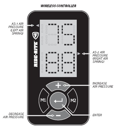
8. ADJUSTING AIR PRESSURE AND UNITS
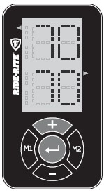
Use the Wireless Controller to adjust the air pressure in your Air Springs. You can select the Air Springs individually, or both at the same time. Determine sides when in vehicle, facing forward. If desired, use the supplied Velcro Tabs to secure the remote to the vehicle.
1 Select Air Spring(s) for pressure adjustment by pressing the Enter Button once for AS-1 (left side), twice for AS-2 (right side) or three times for both sides.
2 Press the Button to increase pressure in selected Air Spring(s).
3 Press the - Button to decrease pressure in selected Air Spring(s).
4 Press the Enter Button to activate the system.
WAIT, THERE’S BAR!
The Wireless Controller settings default to PSI units, but you can adjust the units by following the steps below.
1. Push any button to power on the Wireless Controller and make sure none of the units on the display are flashing.
2. Hold down the Enter Button for a few seconds.
3. Use either the or - Button to select PS for PSI or BR for BAR. Press Enter Button to finalize selection.
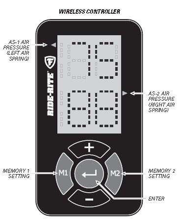
9. WIRELESS CONTROLLER MEMORY SETTINGS AND ERROR CODES
You can set up to 2 memory settings for the system for quick adjustment to frequently used Air Spring settings. M1 is preset for 5 PSI and M2 is preset for 20 PSI.
1 Complete Step 8 to adjust the Air Spring air pressures to desired settings.
2 Press and hold the M1 Button for 3 seconds to save the displayed Air Pressure settings to the M1 memory.
3 Repeat steps 1 and 2 with the M2 Button to save an M2 memory setting.
4 To activate a memory setting, push the desired Memory Button, either M1 or M2.
5 Within one second of pressing M1 or M2, press the Enter Button.
OOPS, SOMETHING WENT WRONG!
Reference the Error Codes below to troubleshoot the problem.
E0: Check power on the ECU (red and yellow wires need 12VDC). Check ground for the ECU (black wire should be attached to the negative battery terminal). Check your wires for any abrasion or heat damage between the ECU and the battery/fuse box. Make sure the Wireless Controller is in range of the ECU (25 ft.). Note that range will vary depending on line-of-sight restrictions.
L0 BR: The batteries in your Wireless Controller are low. Replace both CR2032 coin-cell batteries.
10. TEST THE SYSTEM
With the Air Command F3 Kit and your Air Springs installed, you are ready to test the system.
1. Reattach the negative battery cable.
2. Turn on your vehicle’s ignition.

3. Use the Wireless Controller to inflate the Air Springs to 70 PSI. See Step 8 for details.
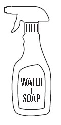
4. Spray fittings with soap and water mixture or glass cleaner.
5. Observe bubbles.
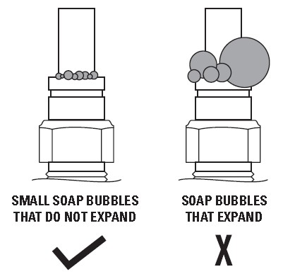
NO LEAKS? Congratulations! You’re riding right with the push of a button! Remember to review the Operating Instructions.
LEAK?
Bummer. Continue to Step 11 to fix the leak.
11. FIX AN AIR LEAK
EXHAUST ALL AIR FROM THE SYSTEM PRIOR TO RELEASING AIR TUBES FROM AIR FITTINGS.
1 Use the Wireless Controller to deflate the Air Springs to 5 PSI. See Step 8 for details.

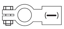
LEAK AT AIR LINE TUBE AND AIR FITTING
Release Air Line Tube (see page 4). Review proper cuts and procedures in Step 5. Repeat Step 5.
LEAK AT BASE OF AIR FITTING

Tighten Air Fitting one turn or until leak stops.

