 FREE 1 to 3-Day Delivery on Orders $149+ Details
How to Install Fabtech 6 in. Basic Lift System w/ Performance Shocks (2014 4WD SuperCrew) on your Ford F-150
- INSTRUCTIONS -
FRONT SUSPENSION
1. Disconnect the negative terminal on the battery. Jack up the front end of the truck and support the frame rails with jack stands. NEVER WORK UNDER AN UNSUPPORTED VEHICLE! Remove the front tires.
2. Remove and discard the factory splash guard under the differential.
3. Locate the sway bar end links and disconnect from the factory lower control arms, save the hardware. Locate the sway bar frame mounts and disconnect them from the frame, remove the sway bar from the truck. Save the hardware and sway bar.
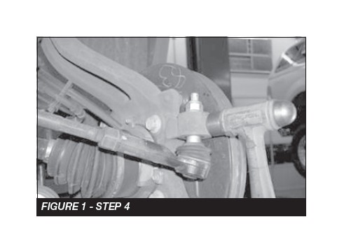
4. Working from the driver side of the vehicle, disconnect the tie rod ends from the steering knuckle by striking the knuckle to dislodge the tie rod end. SEE FIGURE 1
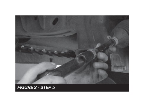
5. Remove factory Tie Rod end and discard. SEE FIGURE 2
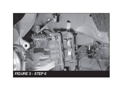
6. Remove the brake caliper and place it next to the frame. Do not overstretch the brake hose when doing so. Retain the hardware for reinstallation. Remove the brake rotor and save. Disconnect the vacuum lines attached to the rear of the hub assembly. Allow the vacuum lines to hang freely. Remove the electronic stability control (ESC) sensor from the top of the hub. Cover the sensor to keep it free from dirt and debris. SEE FIGURE 3
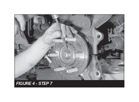
7. Carefully remove the dust cap covering the hub assembly nut. Remove the C.V. bearing nut and save the nut and dust cap. SEE FIGURE 4
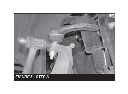
8. Remove the upper and lower ball joint nuts. Disconnect the upper and lower ball joints from the steering knuckle by striking the knuckle with a large hammer next to each ball joint on the knuckle to dislodge the ball joints. Use care not to hit the ball joints when removing. Retain hardware and remove the knuckle with the dust shield and the hub. Use extra care not to over extend the C.V. axle shaft when removing the knuckle. SEE FIGURE 5
9. Remove the four large bolts and three small bolts on the back side of the knuckle. Remove the hub and the actuator from the knuckle. Save hardware for install in the Fabtech knuckle.
10. Remove the bolts on the front side holding the dust shield. Remove the dust shield and discard the factory knuckle.
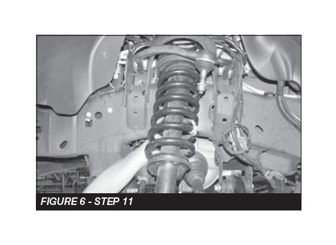
11. Locate the lower shock mount bolt and remove. Save the hardware. Locate the three upper nuts and remove. Save the hardware. Remove the shock assembly from the vehicle and mark “Driver” for assembly to install later with Fabtech shock extensions. SEE FIGURE 6
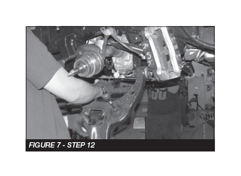
12. Remove the lower control arm bolts from the frame pivots, disconnect upper sway bar nut and remove the lower control arm from the truck. Save hardware and lower control arm. SEE FIGURE 7
13. Repeat steps 4 through 12 on the passenger side of the truck.
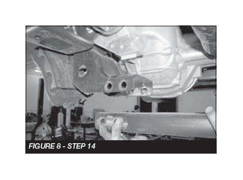
14. Remove the factory rear crossmember from the vehicle and discard the crossmember and hardware. SEE FIGURE 8
15. Remove the front drive shaft bolts where they attach to the front differential. Support the end of the driveshaft before removing the front differential.
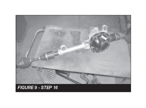
16. Remove the driver side rear differential mount hardware and discard. While supporting the differential, remove the two upper differential mount bolts and remove the differential and axles from the vehicle. Save the hardware. SEE FIGURE 9
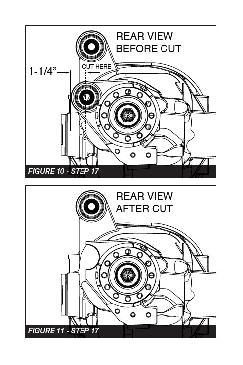
17. Locate rear differential mount closest to the pinion shaft. Mark the mount behind the bushing. Using a die grinder, remove the mount and discard. SEE FIGURES 10-11
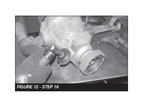
18. Use a sander and remove all sharp edges and burs after the cut. SEE FIGURE 12
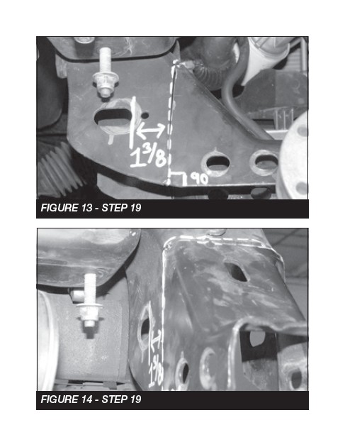
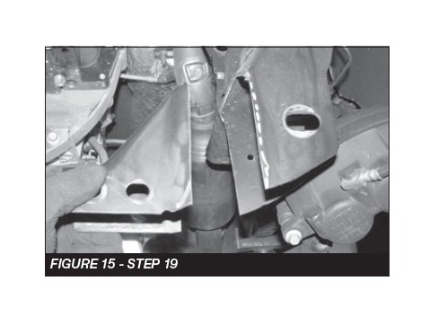
19. Locate the driver side rear lower control arm pocket. Mark the frame 1-3/8’’ from the control arm pivot hole and 90 degrees to the bottom of the pocket where the cross member was mounted. Using a die grinder, cut all the way around the pocket. Discard removed portion of the pocket. SEE FIGURES 13-15
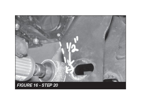
20. Still working on the driver side rear lower control arm pocket, locate the tab on the pocket closest to the front of the vehicle. You will need to sand a radius in the front side of the pocket in order to clear the differential housing. SEE FIGURE 16
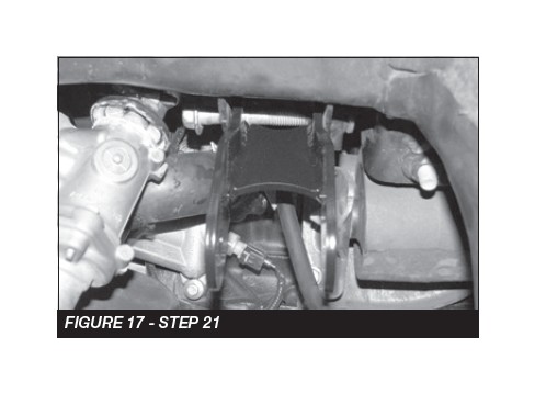
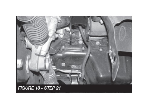
21. Locate the two Fabtech upper differential mounts (FT30378). These upper differential mounts will be placed into the factory upper differential mounts using the factory upper differential mount hardware. Leave the hardware loose in preparation for the differential installation. SEE FIGURES 17-18
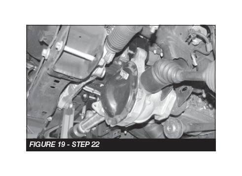
22. Locate the factory front differential and install into the Fabtech upper differential mounts using two ½’’-13 x 4’’ hex cap bolts, washers and lock nuts. Leave all hardware loose in preparation of the installation of the remaining differential mounts. SEE FIGURE 19
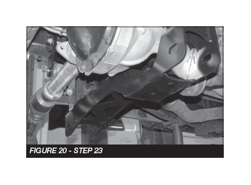
23. Locate the Fabtech rear crossmember (FT30376BK). Install the rear crossmember in the factory rear lower control arm pockets. Mount the crossmember using the factory control arm pivot hardware. Leave all hardware loose. All the tabs on the face of the crossmember should be pointed to the rear of the vehicle. SEE FIGURE 20
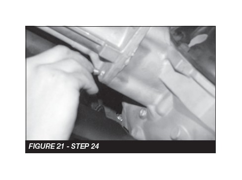
24. Remove the center two differential housing bolts on the back side of the differential and the one on the bottom side. SEE FIGURE 21
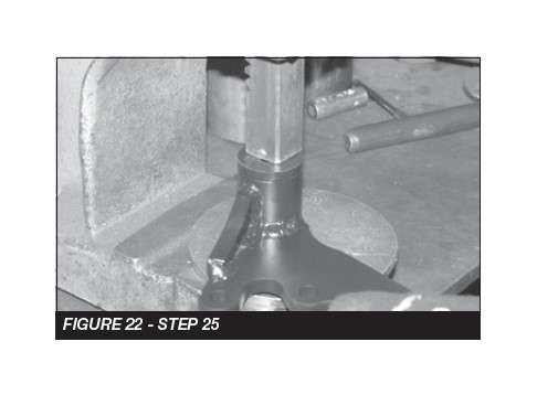
25. Locate the center differential bracket (FT30564). Install two of the Fabtech (FT1020) bushings and one sleeve (FT181) into the barrel on the differential bracket. SEE FIGURE 22
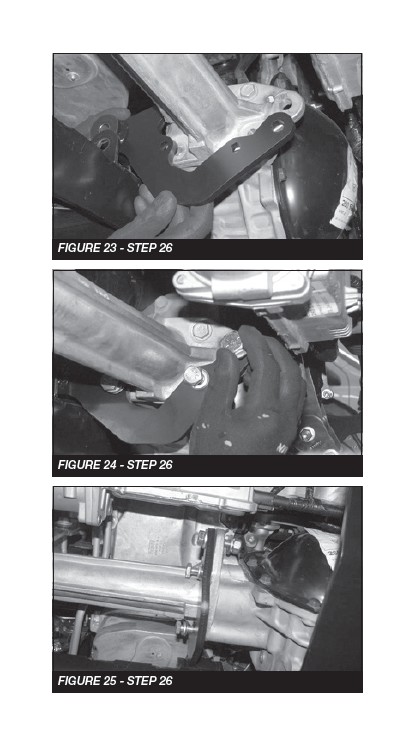
26. Mount the differential bracket to the center of the differential using three M10-1.5 x 45mm bolts, lock washers, and flat washers. Mount the front tab on the diff to the center bracket using one ½-13 x 2” bolt, nut and washers. Leave loose at this time. SEE FIGURES 23-25
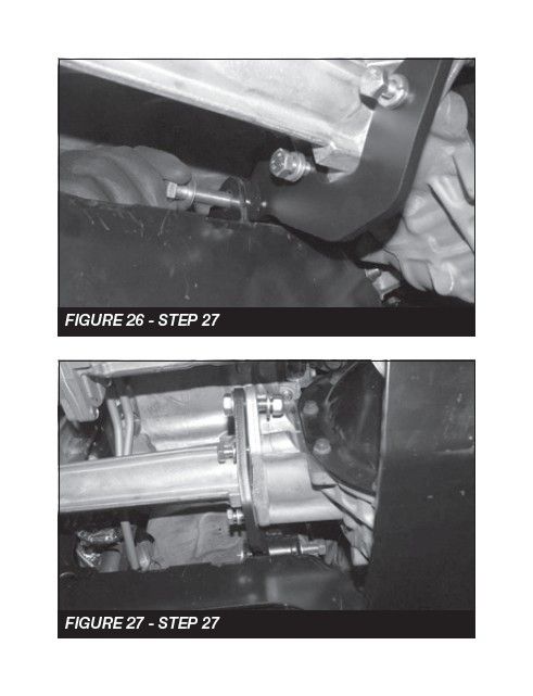
27. Install a ½ -13 x 4” bolt washers and nut through the tabs on the rear crossmember and the bushing on the center bracket. Leave loose at this time. SEE FIGURE 26-27
28. Torque the M10-1.5 x 45mm bolts to 35 ft-lbs. Torque the ½-13 x 2” bolt to 90 ft-lbs.
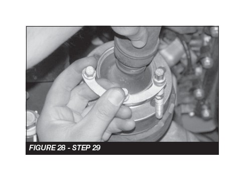
29. Reinstall the front drive shaft with the factory hardware and torque to 35 ft-lbs. SEE FIGURE 28
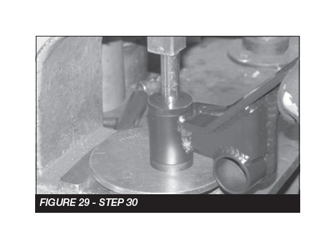
30. Locate the rear diff mount (FT30585BK). Install two of the Fabtech (FT1020) bushings and one sleeve (FT181) into the barrel on the differential bracket. SEE FIGURE 29
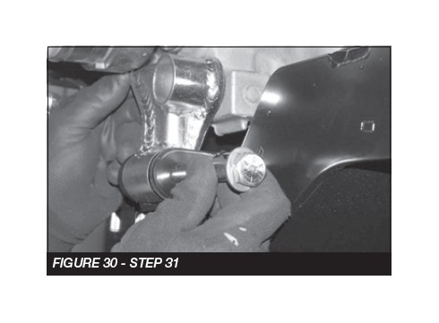
31. Install the rear diff bracket into the tabs on the rear crossmember using a ½-13x4” bolt, washers, and nut. SEE FIGURE 30
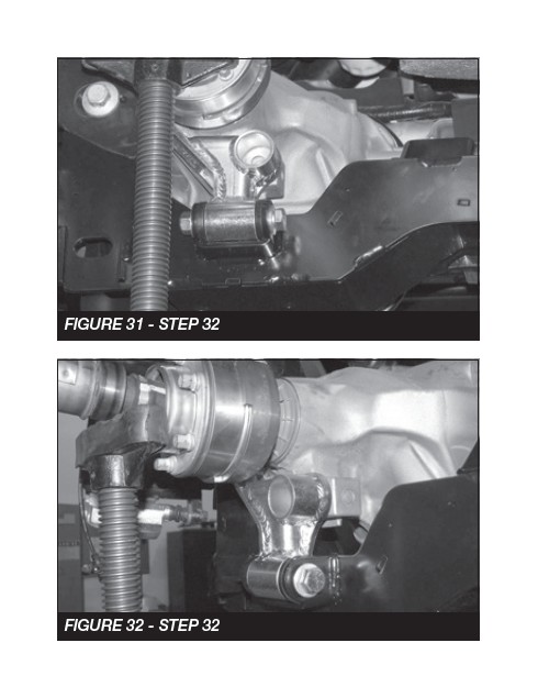
32. Support the diff to make sure the block on the diff is centered with the hole in the rear bracket. SEE FIGURE 31-32
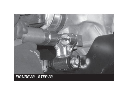
33. Use the rear bracket as a drill guide to drill a ½” hole through the block on the rear of the diff. SEE FIGURE 33
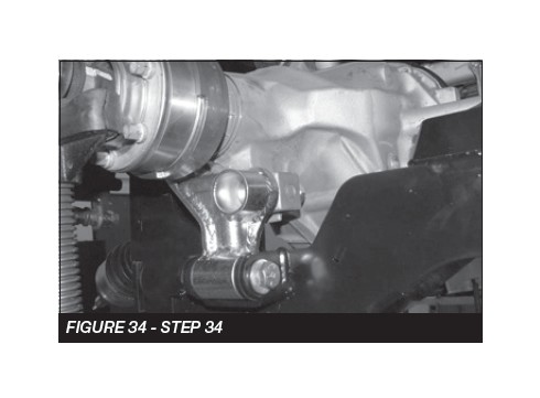
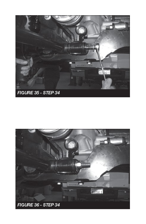
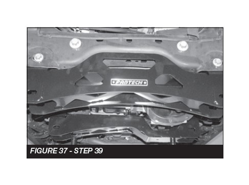
34. Install a ½-13x2 bolt, washers and nut through the bracket and diff. Torque the bolt in the diff to 90 ft-lbs and the bolt in the crossmember to 90 ft-lbs. SEE FIGURE 34-36
35. At this time locate upper differential brackets and torque the factory upper bolts to 90 ft-lbs and lower ½’’ bolts 127 ft-lbs. Locate the center diff mount on the cross member and torque the ½-13 x 4” bolt to 90 ft-lbs.
36. Reinstall the factory vent hose back on to the differential.
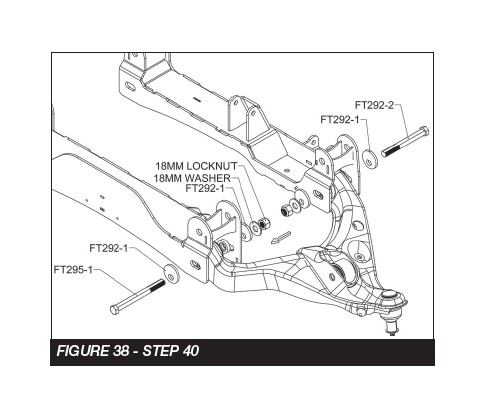
37. Locate the Fabtech front crossmember (FT30375BK). Install the front crossmember into the factory front control arm pockets using the factory hardware. Make sure the skid plate tab on the crossmember is facing the Fabtech rear crossmember. Leave the hardware loose at this time. SEE FIGURE 37
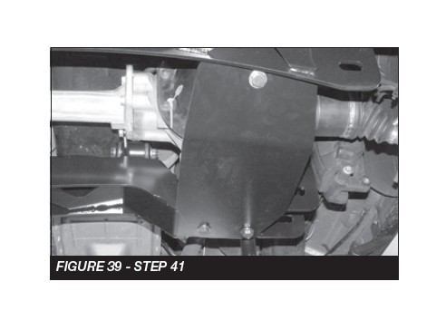
38. Locate the Alignment cam kit (FT295). Locate the factory control arms. Install the lower control arms into the Fabtech crossmembers using the hardware in the cam kit (FT295). Torque the cam bolts at 200 ft-lbs after alignment. SEE FIGURE 38
39. Locate the Fabtech skid plate (FT30377BK) the skid plate will span the distance between the front and rear crossmembers directly under the front differential. Attach the end of the skid plate with the single hole to the tab on the back side of the front crossmember using one ½’’- 13 x 1-1/4 bolt, washers and a C-lock nut. Lift up the back side of the skid plate and install it to the rear crossmember using two ½’’- 13 x 1-1/4 bolts, washers and a C-lock nut. Torque all hardware to 127 ft-lbs. Tourque crossmember bolts to 240 ft-lbs. SEE FIGURE 41
If installing Dirt Logic coilovers (FTS221341) do so at this time, using the instructions provided in the shock box. Once finished, you may skip to STEP 43.
If using the factory coilover continue to STEP 40.
40. Locate the FT30558BK DRVR and FT30559BK PASS shock spacers.
41. Locate the factory coilovers.
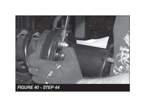
42. Install the Driver side spacer on the driver side coilover using the factory hardware and torque to 35 ft-lbs. Repeat on the passenger side. SEE FIGURE 40
43. Install the coil over into the frame bucket. Rotate lower mount inline with the control arm tabs, and the pivot at the control arm using the factory hardware. Torque the upper nuts to 35 ft-lbs and the lower pivot to 100 ft-lbs.
44. NOTE: Specifc IWE “Integrated Wheel End” installation procedures are necessary when servicing and/or IWE vacuum is released. When the IWE actuator is loosened at the knuckle and/or removed from CV shaft:
• Remove the two vacuum line, compress the IWE actuator and install a vacuum cap on the larger vacuum port (to keep it compressed).
• Install the IWE actuator onto the halfshaft outer end (if removed).
• Do not dislodge the IWE seal spring when installing an IWE on a CV halfshaft outboard end or component damage may occur.
• Allow the wheel knuckle to swing outward while keeping the halfshaft pushed inward.
• Once clearance is available, install the halfshaft outboard end into the wheel knuckle hub bearing.
• Connect the upper ball joint and install new nut; torque to 85 ft-lbs.
• Install the three IWE actuator to wheel knuckle retaining bolts; torque to 106 ft-lbs
• Remove the IWE vacuum cap and reconnect the vacuum tubes.
• Verify the spline engagement by checking for spline lash before installing the axle nut or component damage may occur.
• Install new axle nut; 30 ft-lbs
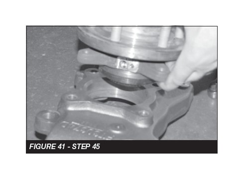
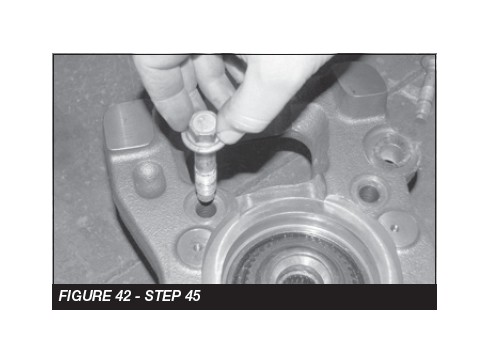
45. Locate the Fabtech driver side spindle (FTS30374D) and install the factory hub. Torque the four 14mm bolts to 160 ft- lbs. SEE FIGURES 41-42
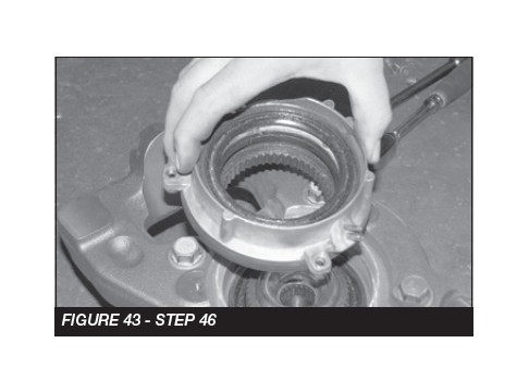
46. Locate the factory 4WD actuator and install into the Fabtech spindle. Torque the factory 8mm bolts to 17 ft-lbs. SEE FIGURE 43
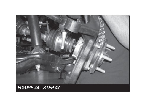
47. Install the Fabtech knuckle onto the upper and lower control arms. Torque the upper ball joint to 85 ft-lbs and the lower ball joint to 110 ft-lbs. SEE FIGURE 44
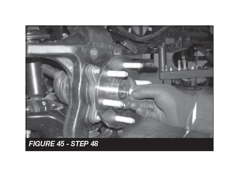
48. Install the dust shield and torque to 14 ft-lbs. Install CV shaft nut and torque to 35 ft-lbs. Install the factory dust cover. SEE FIGURE 45
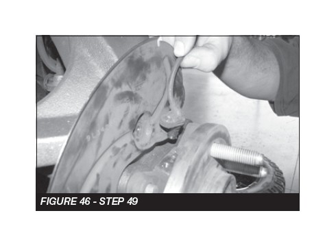
49. Install the ABS wheel speed sensor. Make sure the end of the sensor is clean. SEE FIGURE 46
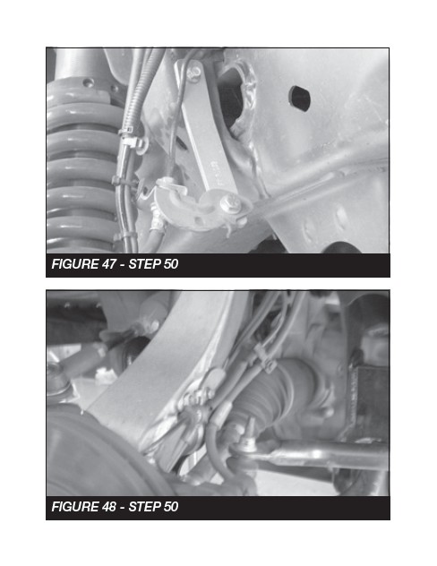
50. Carefully pull some slack from the frame side and reconnect the vacuum line to the hub assembly. Install the Fabtech frame brake line bracket (FT70032). Using the factory hardware, mount factory brake line bracket to the side of the Fabtech knuckle. After installing the factory brake line bracket, check to insure full movement by steering the knuckle back and forth, and make sure none of the ABS lines, brake lines, or vacuum lines are inhibited during full test movement of the knuckle. SEE FIGURES 47-48
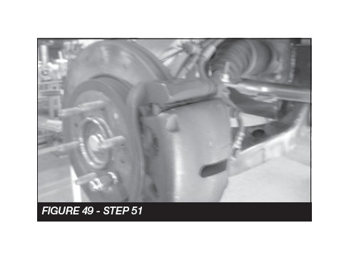
51. Reinstall the original brake rotor, followed by the brake caliper. Use a small amount of the supplied thread lock compound on the caliper bolts and torque to 145 ft-lbs. SEE FIGURE 49
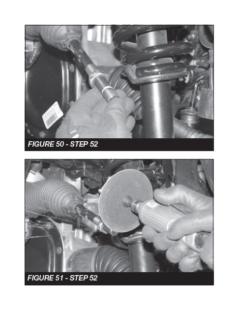
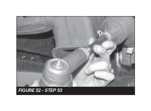
52. Locate the factory tie rod. Trim 1’’ off the end. SEE FIGURES 50-52
53. Locate the Fabtech tie rod end (FT20277). Install the tie rod end on the tie rod. Torque to 60 ft-lbs. SEE FIGURE 52
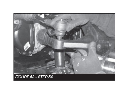
54. Reconnect the tie rod end to the steering knuckle and torque to 60 ft-lbs. SEE FIGURE 53
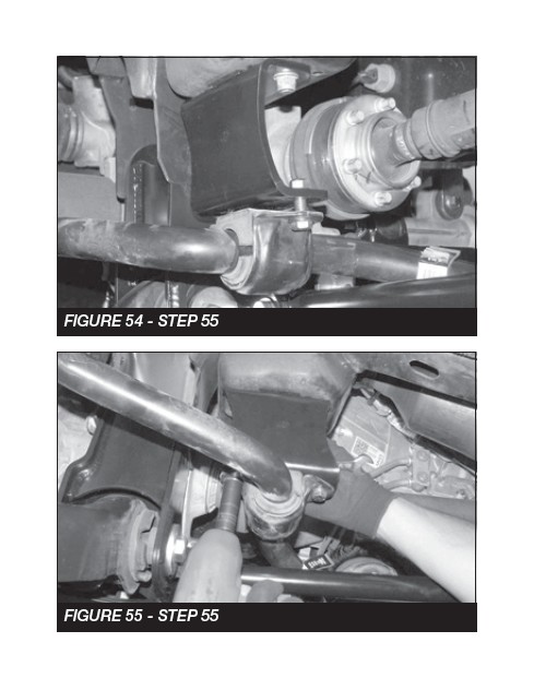
55. Install the factory sway bar to the frame using the FT30063BK driver side bracket and the FT30062BK passenger side bracket. SEE FIGURES 54-55
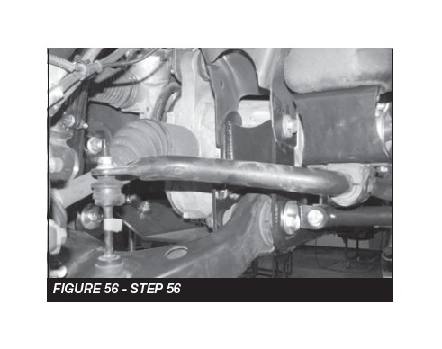
56. Install the sway bar end to the factory lower control arm using the factory end links. SEE FIGURE 56
REAR SUSPENSION
57. Jack up the rear end of the vehicle and support the frame rails with jack stands. Release the parking brake at this time. Supporting the rear differential, remove the rear shocks, u-bolts, blocks and lower axle down. Use care not to over extend the brake hose.
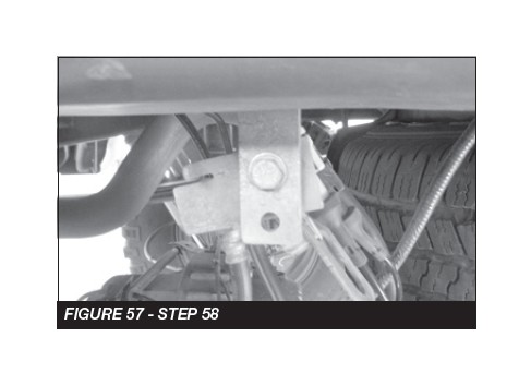
58. Locate the factory brake line mount on the driver side of the frame. Locate the supplied brake line bracket (FT70033) and attach the bracket between the factory fame mount and the factory brake line. SEE FIGURE 57
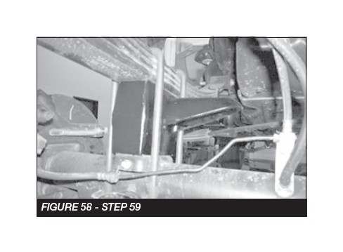
59. Locate and install the rear lift blocks FTBK52. The extended bump stop perch will be facing inboard of the truck. Using the provided u-bolts, nuts and washers, align the axle, lift blocks, and springs and torque u-bolts to 90 ft-lbs. SEE FIGURE 58
60. Locate FTS7266 rear shocks (not included with kit). Install the supplied shock sleeves from bag 143002 into each end of the shocks. Install the shocks using the factory hardware and torque upper and lower bolts to 45 ft-lbs.
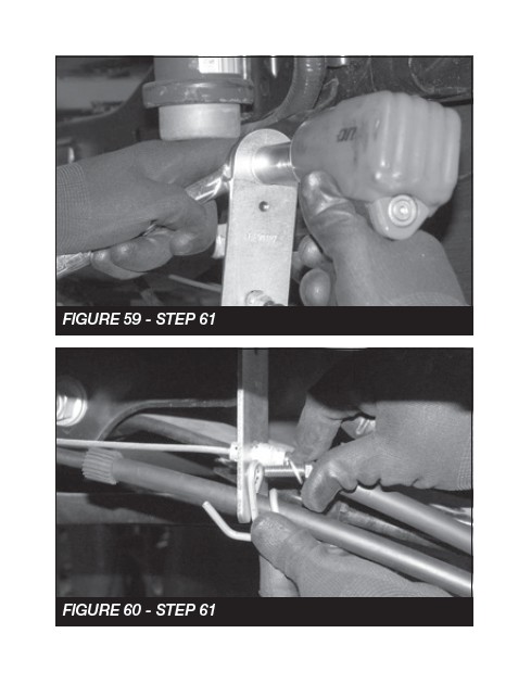
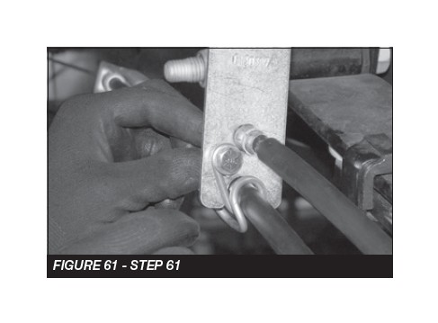
61. Locate E-brake bracket (FT30387) and mount to the factory E-brake cable mount and reinstall the E-brake cable into the Fabtech bracket. SEE FIGURES 59-61
62. Install tires and wheels and torque lug nuts to wheel manufacturer’s specifications. Turn front tires left to right and check for appropriate tire clearance. Note - Some oversized tires may require trimming of the front bumper & valance.
63. Check front end alignment and set to factory specifications. Readjust headlights.
64. Recheck all bolts for proper torque.
65. Recheck brake hoses, ABS wires and suspension parts for proper tire clearance while turning tires fully left to right.
66. Check the fluid in the front and rear differential and fill if needed with factory specification differential oil. Note - some differentials may expel fluid after filling and driving. This can be normal in resetting the fluid level with the new position of the differential/s.
67. Install Driver Warning Decal. Complete product registration card and mail to Fabtech in order to receive future safety and technical bulletins on this suspension.
Vehicles that will receive oversized tires should check ball joints and all steering components every 2500-5000 miles for wear and replace as required.
RETORQUE ALL NUTS, BOLTS AND LUGS AFTER 50 MILES AND PERIODICALLY THEREAFTER.
