FREE 1 to 3-Day Delivery on Orders $149+ Details
How to Install Edelbrock E-Force Stage 1 Street Supercharger w/ Tuner (09-10 2WD 5.4L) on your Ford F-150
Tools Required
- Jack and Jack Stands OR Service Lift
- Panel Puller
- Ratchet and Socket Set including Metric & SAE
- 12” Ratchet Extension Bar
- 1/2” Breaker Bar
- Flat Blade & Phillips Screwdrivers
- Torx T-20 and T-30 Driver
- 1/8” Allen Wrench
- 5/8” Fuel Line Removal Tool
- Torque Wrench
- Vice
- Vacuum Pump Kit
- Pliers OR Hose Clamp Removal Tool
- Hacksaw, Drill & File OR Grinding & Cut-Off Wheels
- Impact Wrench
- Terminal Removal & De-Pinning Tools OR Safety Pin
- Blue Loctite
- O-ring Lube
- Masking Tape
- Engine Oil & Filter
- Fan Clutch Nut Wrench
- Needle Nose Pliers

Shop Parts in this Guide
Test Flash Procedure
Use the supplied programmer to flash the ECU and verify its compatibility.
“Original Equipment Manufacturers often release updates to the computer programming for your vehicle. Edelbrock highly recommends that you verify, with your new car dealer, that your vehicle is equipped with the latest software version from your vehicle manufacturer, before attempting to load the Edelbrock tune.”
• Confirm that you have the latest calibration by checking the Edelbrock website (http://www.edelbrock.com/ automotive_new/mc/ superchargers/software-tech.shtml ) Once you have found the latest tune on the site, power on the programmer, press the left arrow and select the Device Info option. Scroll down to Tune Version and compare that number to the one on the site. If they are different, download the new calibration as instructed on the website.
• Connect the supplied PCM cable on the handheld programmer to the OBD-II connector located below the steering wheel in the passenger compartment.
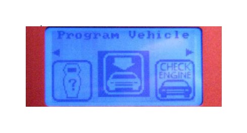
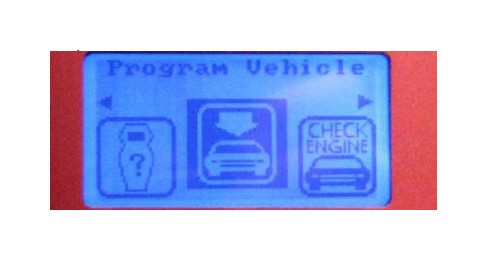
• Use directional pad to highlight Program Vehicle option and press Select button.
• Use directional pad to highlight Pre-programmed Tune option and press Select button.
• Read disclaimer then press Select to continue.
• Verify ignition is in the ‘Key On’ position but that the engine is not running then press Select.
• Use directional pad to highlight your vehicle and transmission combination then press Select.
• Use directional pad to highlight Begin Program then press Select.
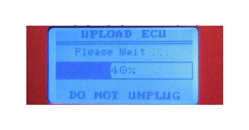
• Five separate operations will take place during this step. Completion of each operation will cause the progress bar to reset to zero.
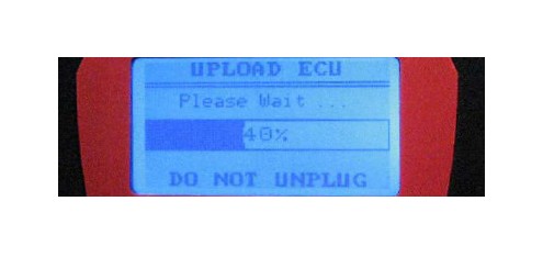
DO NOT unplug the programmer until prompted.
• Turn the vehicle off when prompted to do so by the handheld programmer.
• Read parting message from programmer then press Select to continue.
• Unplug the programmer cable from the OBD-II port.
In the rare occurrence that you encounter an error message during the test flash procedure, please refer to pg. 29.
Post Successful Test Flash
If you are ready to install the supercharger, proceed to Step 1 of the Supercharger Installation
OR
If you wish to return the ECU back to the factory calibration, such that the vehicle can still be driven until you are ready to begin the installation, then:
• Put the car into Acc mode, but don’t start the vehicle.
• Connect the supplied PCM cable to the OBD-II connector.
• Use directional pad to highlight Program Vehicle option and press Select button.
• Use directional pad to highlight Return To Stock option and press Select button.
• Follow the on screen instructions then turn the vehicle off when prompted to do so by the handheld programmer.
• Read parting message from programmer then press Select to continue.
• Unplug the programmer cable from the OBD-II port.
• When you are ready to Install the supercharger, proceed with Step 1 and you will be prompted to re-flash the ECU towards the end of the installation procedure.
Supercharger Installation
1. Use an 8mm socket to loosen the negative battery terminal clamp, remove the cable and tuck it to the side.
2. Use a 10mm socket to remove the nut on the positive battery terminal that retains the alternator power cable. Detach this wire from the terminal, then loosely reinstall the nut.
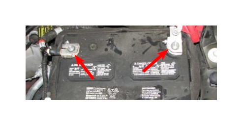
3. Use an 8mm socket to loosen and remove the positive battery terminal clamp, then tuck the wire aside.
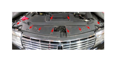
NOTE: Steps 4-10 is the front fascia removal process for the Expedition/Navigator installations only. Disregard otherwise.
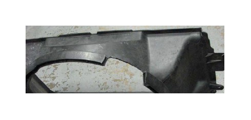
4. Using a panel removal tool, remove the upper air deflector by removing the 10 pin-type retainers.
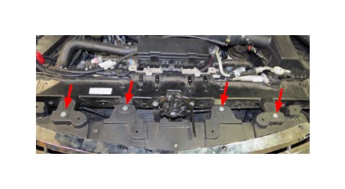
5. Remove four (4) grill-to-radiator support bolts using a Torx T-30 driver.
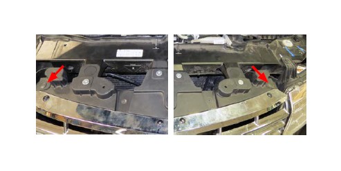
6. Using a panel removal tool, remove two (2) upper pin-type retainers for the lower air deflector.
7. Using a panel tool, remove three (3) lower air deflector pin-type retainers located underneath the vehicle.
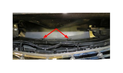
8. Remove two (2) lower air deflector pin-type retainers located behind the fascia cover.
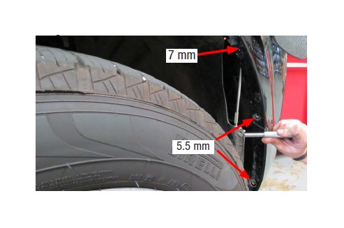
9. Remove four (4) passenger and driver side front fascia cover to fender bolts using a 7 mm socket. Remove four (4) passenger and driver side front fender splash shield bolts using a 5.5 mm socket.
10. Disconnect the fog lamp and parking aid sensors if equipped. Carefully remove the front fascia and set aside.
11. Loosen the two hose clamps retaining the air inlet tube and remove.
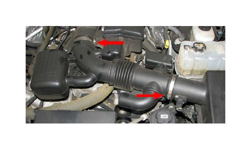
12. Disconnect the PCV tube running between the throttle body elbow and the passenger side valve cover.
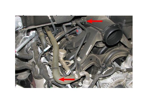
13. Use a 10mm socket to remove the inlet resonator bolt, then loosen the hose clamp and remove the resonator.
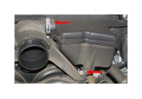
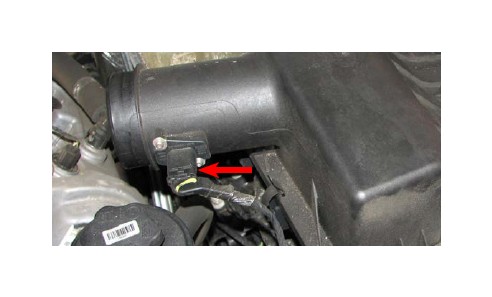
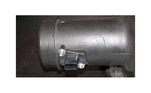
14. Detach the electrical connector from the MAF sensor on the air box cover.
15. Remove the air box cover and stock air filter.
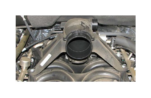
16. Use a 10mm socket to remove the three remaining bolts that hold the throttle body elbow to the intake manifold. Lift and remove the elbow.
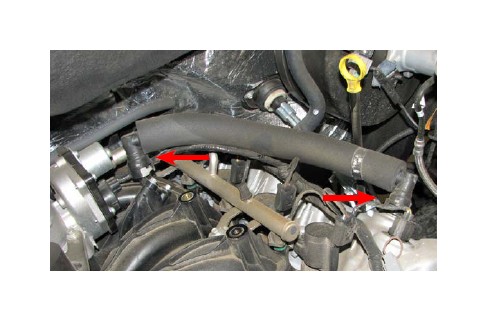
17. Detach and remove the driver side PCV tube from the intake manifold and valve cover.
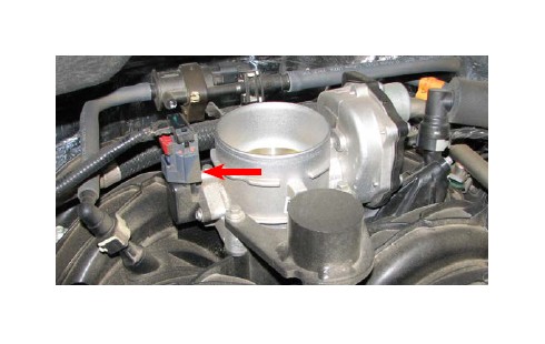
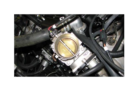
18. Detach the throttle position sensor (TPS) connector from the driver side of the throttle body.
19. Use an 8mm socket to remove the two front throttle body bolts then remove the throttle body weight.
20. Use an 8mm socket to remove the two remaining throttle body bolts.
21. Lift the throttle body slightly, then pull back the red tab on the electronic throttle control (ETC) connector and detach it. The throttle body can now be removed and set aside.
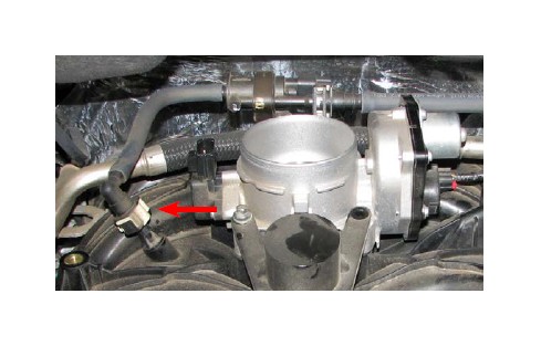
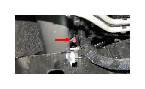
22. Disconnect the EVAP hose from the passenger side of the manifold. Disconnect the electrical connector from the purge solenoid, then slide the solenoid off its bracket and push the assembly to the driver side of the engine.
23. Disconnect the fuel inlet hose from the fuel rails by sliding off the lock clip and depressing the blue tab. Use a
24. Disconnect the electrical connector from each of the fuel injectors.
25. Pull the wiring harness off the two studs on the rear of the intake manifold.
Brochure #63-1583 Rev - 3/26/13 - QT/mc
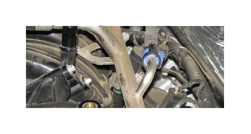
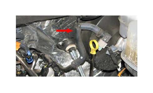
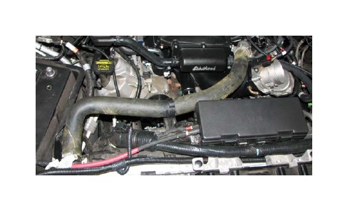
26. Disconnect the brake booster hose assembly from the brake booster fitting.
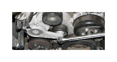
27. Insert a 1/2” drive breaker bar into the square hole of the belt tensioner. Push the breaker bar towards the driver side fender then remove the serpentine belt.
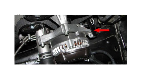
28. Separate the wire harness from the alternator strap.
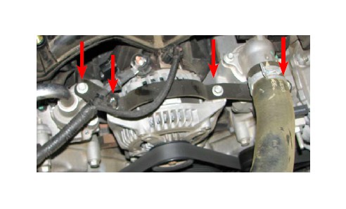
29. Use a 10mm socket to remove the four bolts that retain the upper alternator strap.
30. Remove the electrical connector from the alternator. Use a 10mm socket to remove the nut retaining the power wire. Remove the power wire and replace the nut.
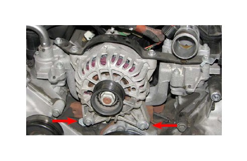
31. Support the alternator while using a 10mm socket to loosen the two bolts that support the alternator. Lift the alternator off these bolts and set it aside. The two long bolts can be removed, as they will not be reused.
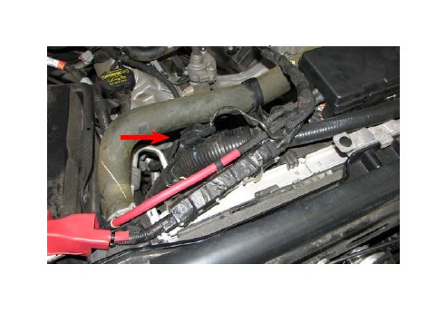
32. Trace the alternator power wire back to the harness connector, on the passenger side of the radiator, and disconnect it then remove the entire power wire harness.
33. Use a 10mm socket and a short extension bar to remove the ten intake manifold bolts then lift and remove the intake manifold.
34. Use a soft cloth to clean the deck surface of the cylinder heads. Use two strips of masking tape to cover the intake ports, to prevent any debris from entering the ports.
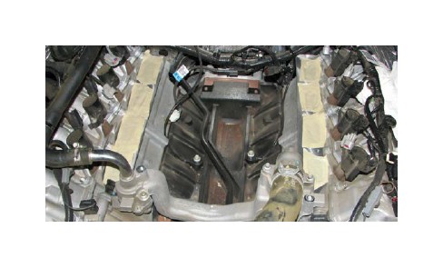
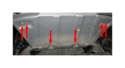
35. For trucks equipped with a skid plate, use a 15mm socket to remove the six bolts holding it in place then set it aside.
36. Locate the petcock at the bottom of the radiator and place a drip pan below it. Open the petcock to drain the cooling system. Close the petcock once the cooling system has been drained. (Attaching a small hose to the petcock nipple will make this procedure a lot less messy.)
37. Use a pair of pliers or a clamp removal tool to remove the upper radiator hose.
38. Use a screwdriver to remove the clamp that holds the heater hose to the water crossover then pull off the hose.
NOTE: The following fan removal procedure only applies to 2009 trucks equipped with a clutch fan. 2010 trucks equipped with an electric fan should skip ahead to step #48.
39. Pull the three wire harness retaining pins out of the fan shroud and push the harness back towards the firewall.
40. Un-clip the power steering hose from the top of the radiator. It is located on the drivers side.
41. Remove the bolt retaining the power steering reservoir and push the reservoir back towards the firewall.
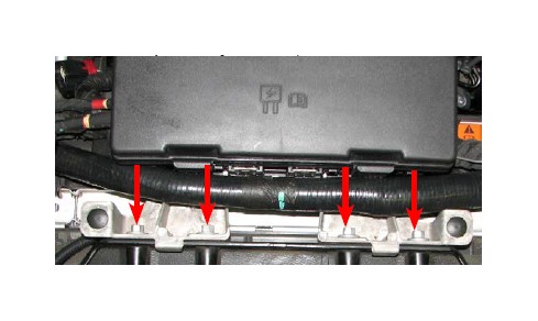
42. Remove the four bolts retaining the fuse box then push the fuse box back towards the firewall.
43. Remove the two bolts holding the fan shroud.
44. Reach up from below the vehicle and push the lock tab. It is located on the bottom of the shroud over the frame rail. Continue by flipping the lower portion of the shroud forward and up.
45. Disconnect the fan clutch control wire harness connector then slide the brown connector off its bracket.
46. Lift the fan shroud up and out of the engine bay; this will require a fair amount persuasion, so please be patient.
47. Use a fan clutch nut wrench and a fan pulley holding wrench to loosen and remove the radiator fan.
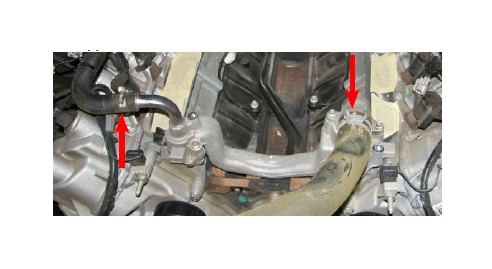
48. Use an 8mm socket to unbolt the thermostat housing and remove it. The housing, thermostat and O-ring will all be reused.
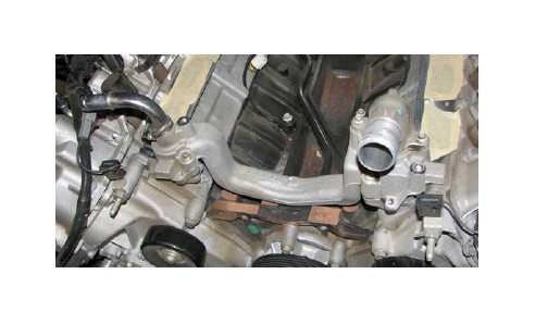
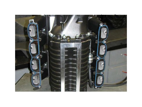
49. Use an 8mm socket to unbolt and remove the water crossover from the engine. Remove the gaskets on each end and retain them, as they will be reused. Then place making tape over each water passage.
50. Use a 15mm wrench to remove the nut from the stud located at the top of the engine cover, on the driver side. Use an 18mm wrench to then remove the stud and install the M8 x 65mm bolt supplied in Bag #3 in its place.
51. Carefully remove the intake gaskets from the intake manifold by pushing the clips out of each hole in the flange.
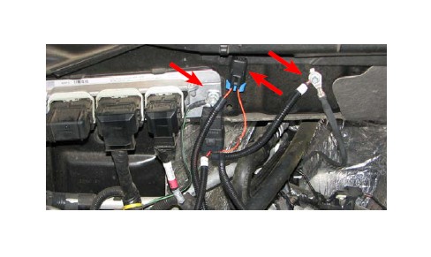
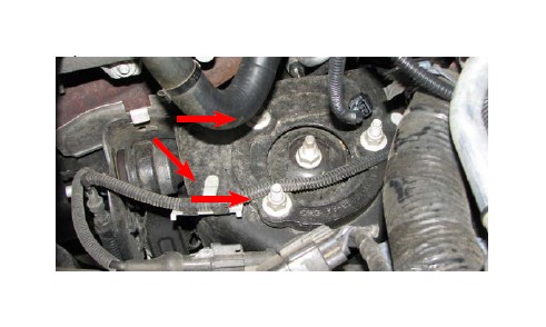
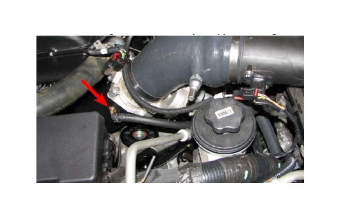
52a. (Customers installing the Supercharger on a F-150 only) Locate the engine ECU on the passenger side of the firewall and mount the water pump relay on the stud located to the right it. Mount the ground strap to the bolt to the right of the ECU.
52b. (Customers installing the Supercharger on an Expedition/Navigator only) Mount the water pump relay and ground strap to the stud on the left of the ECU, located on the passenger side of the firewall.
53a. (Customers installing the Supercharger on a F-150 only) Mount the water pump fuse holder on the small bolt directly above the relay mounting location.
53b. (Customers installing the Supercharger on an Expedition/Navigator only) The water pump fuse holder may need to be mounted to the left side of ECU.
54. Route the positibe ( ) battery wire from the fuse holder to the positive battery terminal.
55. Route the water pump connector from the supplied water pump harness to the front of the radiator, on the passenger side.
56. Attach the corresponding end of the supplied TPS Extension harness to the TPS connector on the stock harness, then set the harness aside.
57. Locate the EVAP solenoid connector, which extends from the main wire harness at the rear of the engine bay, and connect it to the EVAP Purge Solenoid Extension harness. Route the extension harness over to the EVAP purge solenoid and plug it in.
58. Route the water pump Key-on Power Wire around the back of the engine and plug it into the matching connector coming off of the EVAP extension harness.
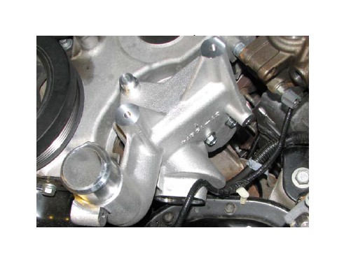
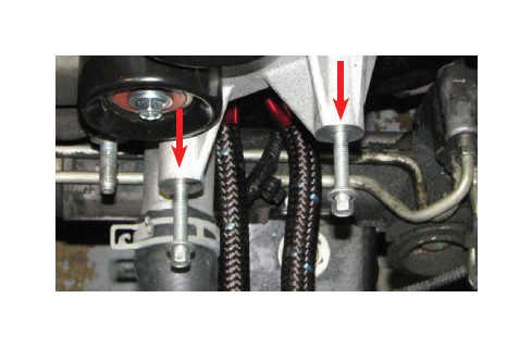
59. Unbolt and remove the idler pulleys on the driver side.
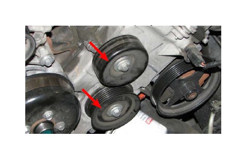
60. Use the stock bolts, in their original locations, to install the supplied idler pulleys on the two, front cover, bosses; the 90mm grooved pulley goes on the top boss, the 76mm smooth pulley goes on the lower boss.
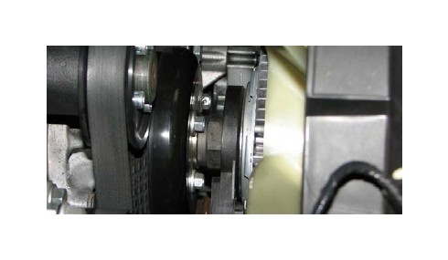
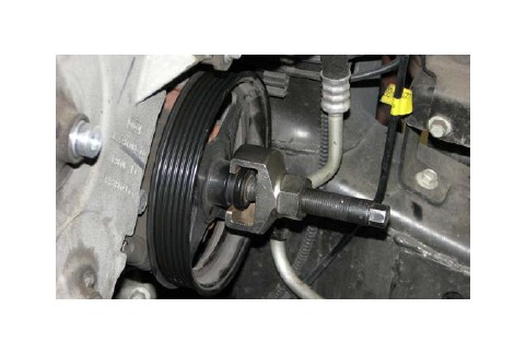
61. Use a pulley removal tool to remove the power steering pump pulley.
62. Use a turkey baster, hand pump or siphon to drain the power steering fluid reservoir.
NOTE: Several of the following steps are more easily accomplished by working from below the truck. A service lift is the preferred method of accessing the undercarriage, but an appropriately load-rated jack and jack stands will work, as well.
63. Position a drain pan below the radiator then disconnect the lower radiator hose from the engine.
64. Use needle nose pliers or a flat blade screwdriver to remove the e-clip from the plastic hose fitting that holds the lower radiator hose to the radiator, Then remove the hose.
65. Position a drain pan below the oil filter and power steering pump.
66. Remove the oil filter and allow engine oil to drain. It is not necessary to fully drain the oil pan.
67. Use a 10mm socket to unbolt and remove the oil splash shield.
68. Remove the plastic elbow fitting from the lower radiator hose by cutting the plastic retaining ring with a hacksaw or cut-off wheel. CAUTION: Avoid damaging the fitting itself, as it will be reused.
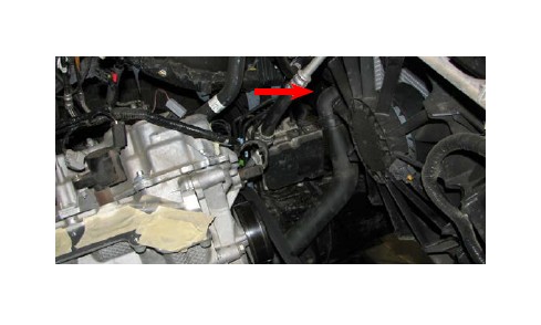
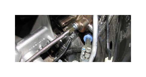
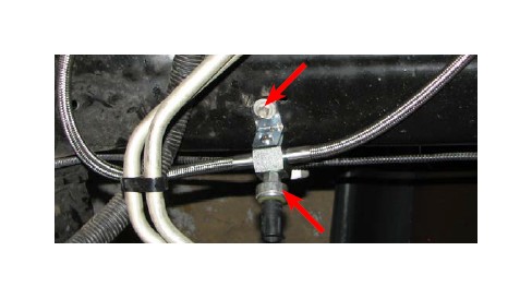
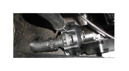
69. Use a 15mm deep socket to remove the nut securing the power steering hard line to the front cover stud.
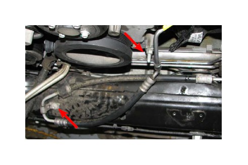
70. Use a 10mm socket to remove the bolt securing the power steering pressure line to the crossmember.
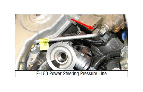
71a. (Customers installing the Supercharger on a F-150 only) Use an 18mm wrench to remove the power steering pressure line from the under side of the pump. If the power steering line has a sensor in it, pry up the lock tab and remove the connector.
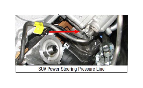
71b. (Customers installing the Supercharger on an Expedition/Navigator only) Remove the bolt that holds the power steering pressure line retention-bracket onto the under side of the pump.
72. Use a 10mm socket to remove the bolt that holds the power steering line retention bracket onto the rack & pinion. Save this bolt, as it will be re-used.
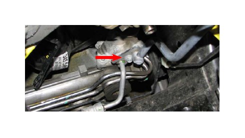
73. The power steering pressure line can now be pulled out of the steering box and removed from the vehicle.
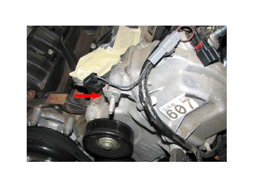
74. Depress the locking tab and pull the electrical connector off the oil pressure sensor that is located on the oil filter bracket.
75. Use a 10mm universal socket and an extension bar to remove the four bolts that retain the oil filter bracket to the side of the engine block. Remove and save the gasket for later use
76. Use a 12mm wrench to remove the front cover bolt adjacent to the oil filter bracket.
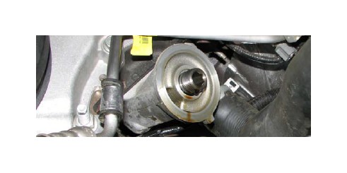
77. Use a 21mm wrench to remove the oil pressure sensor from the filter bracket.
NOTE: 4wd trucks will need to use the bracket supplied with the Edelbrock kit#15834 for the following steps. 2wd trucks should use the bracket supplied in #1583 supercharger box.
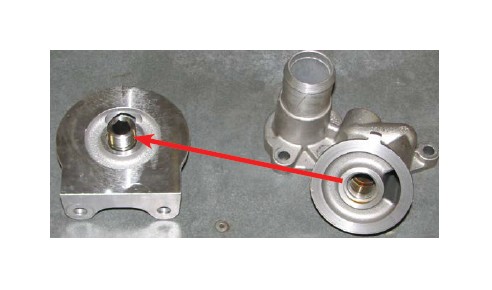
78. Apply thread sealant to the threads of the supplied plug and the stock oil pressure sensor then install them in the supplied oil filter bracket.
79. Place the oil filter bracket gasket on the flange of the supplied bracket. Once the bracket is close enough, attach the electrical connector to the oil pressure sensor.
80. Use the (2) M8 x 75mm long bolts from Bag #3 to hold the gasket in place while aligning the flange of the supplied oil filter bracket to the block. Finger tighten these bolts until the bracket is flush to the block
81. Install the short M8 x 35mm bolt from Bag #3 onto the bracket. NOTE: A swivel 10mm socket and extension bar are strongly recommended to facilitate installation of the bottom bolt.
82. Loosely install the supplied 67mm idler pulley to the front boss of the oil filter bracket; utilize the M8 x 90mm bolt and washer that are supplied in Bag #3.
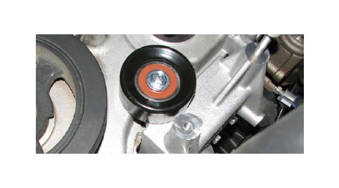
83. Tighten down the four mounting bolts, then tighten the pulley bolt. Verify that the pulley can spin freely once all the filter bracket bolts have been tightened.
84a. (Customers installing the Supercharger on a F-150 only) Install the fitting on the straight side of the supplied power steering hose onto the pump. The fitting going into the pump should be tightened to 48 ft lb.
84b. (Customers installing the Supercharger on an Expedition/Navigator only) Remove the fitting installed on the straight side of the supplied power steering pressure hose, as it will not be utilized. Utilize the O-ring & backup ring from the OE fitting onto the supplied fitting found in bag #7.
NOTE: Pay attention to the order of each ring before removing. Connect the P.S. hose to the fitting and tighten. Insert the fitting into P.S. pump then secure the supplied spacer and hold down plate with the supplied bolt. Ensure that the spacer is on the bolt, in-between the P.S. pump and the hold down plate.
85. Route the power steering hose along the crossmember and back to the power steering rack. Secure it to the crossmember with the stock bolt. Use the supplied wire ties to isolate the hose away from any moving parts.
86a. For vehicles that utilize a power steering pressure sensor: Remove the sensor from the stock power steering line and install it in the new power steering hose then attach the wire harness connector.
86b. For vehicles w/o a power steering pressure sensor: Install the O-ring pipe plug, supplied in Bag #6, into the tapped hole of the new hose .
87. Tighten the fitting supplied on the 90° end of the power steering pressure line then insert it into the power steering rack. Use the stock bolt and bracket to secure the fitting to the rack.
88. Use a 1/2” allen wrench to remove the oil filter fitting from the stock oil filter bracket. 2wd trucks will install it in the supplied oil filter bracket while 4wd trucks will install it in the remote filter bracket supplied with the #15834 4wd Kit.
89. 2wd trucks should now install the oil filter on the new bracket, while 4wd trucks should refer to the instructions supplied with the #15834 kit
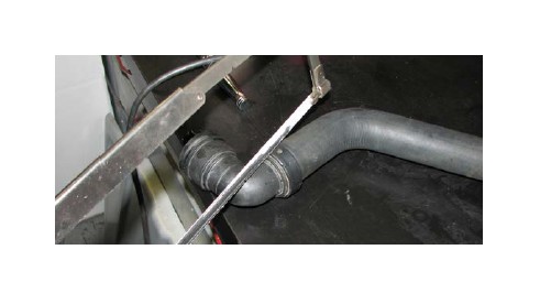
90. Cut the supplied lower radiator hose on the dotted line, as shown below.
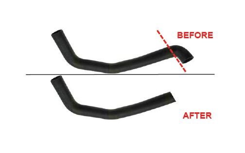
91. Continue, by Inserting the OE plastic elbow fitting into the hose and secure it with the supplied hose clamp.
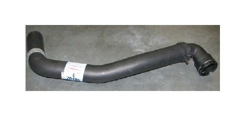
89. Install the lower radiator hose between the oil filter bracket and the radiator. Secure the hose to the bracket with the stock hose clamp then secure the elbow fitting to the radiator by reinserting the stock wire clip.
93. Use a pulley installation tool to reinstall the power steering pump pulley.
94. Install the M8 x 45mm alternator bolts supplied in Bag #3 into the new oil filter bracket.
95. Slide the stock protective boot onto the ring terminal end of the supplied Alternator Power Harness then install the ring terminal on to the power stud of the positive battery terminal and secure it with the stock nut.
96. Attach the supplied Alternator Power Harness to the connector at the top of the radiator. The connector is located on the passenger side.
97. Loosen the four fuse box mounting bolts. (If they haven’t been previously removed).
98. Route the alternator wire harness along the top of the radiator, working it below the fuse box support brackets, then plug it into the alternator.
99. Remove the nut on the alternator power stud and install the supplied power wire so that the harness extends in the opposite direction of the alternator mounting ears. Re-use the stock plastic wire boot. Tighten the nut once the power wire is installed then slide the boot over the nut.
100. Loop the supplied serpentine belt around the alternator pulley with the ribbed side facing the pulley and the belt going around the upper bolt boss of the bracket. Lift the alternator into place and snug the mounting bolts but do not fully tighten them at this time.
101. Position the alternator support straps so that they align with the bolt provisions on the alternator and the oil filter bracket. Snug the supplied strap bolts, then hold the alternator firmly against the bracket while torquing the bracket bolts to 18 ft-lbs, then torque the strap bolts to 8 ft-lbs. Make sure the belt stays between the strap and the upper bolt boss.
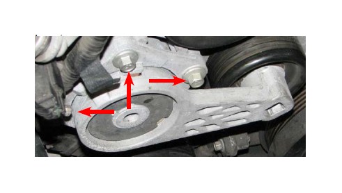
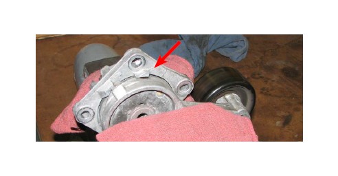
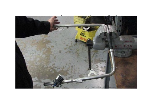
102. Remove the three bolts holding the belt tensioner in place, and remove the tensioner.
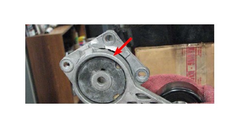
103. Place the tensioner in a cloth wrapped vice and use a grinding wheel or hacksaw to remove the stop.
104. Use a grinding wheel or file to ensure that the area that was ground down is smooth and free of burrs.
105. Align the two pieces of the tensioner brace so that the bolt holes line up and the script is facing out then install the three M6 x 25mm bolts supplied with the brace.
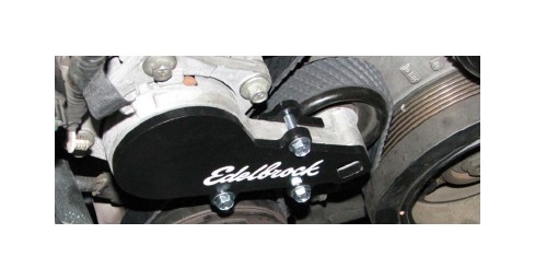
106. Use the stock bolts to reinstall the tensioner.
107. Remove the tape covering the water passages in the cylinder heads. Apply the stock gaskets to the new water crossover, then lower the crossover onto the heads. Install the M6 x 45mm bolts supplied in Bag #4 and torque them to 8 ft-lbs.
108. Remove the tape covering the intake ports of the cylinder heads and supercharger runner flanges.
109. Install the stock intake gaskets onto the runner flanges of the supercharger assembly.
NOTE: Not every lock tab will have a corresponding hole.
110. Lift the supercharger assembly, with the flange gaskets in place, over the water crossover and onto the engine. Insert the M6 x 30mm manifold bolts supplied in Bag #1 into their provisions to determine when the manifold is properly aligned.
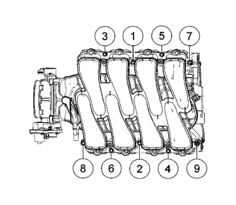
111. Torque the manifold bolts to 89 in-lbs. in the sequence shown below.
112. Attach the stock heater hose to the passenger side fitting on the supplied water crossover then secure it with the stock hose clamp.
NOTE: Steps 113-116 pertains to 2007-08 Expedition/ Navigator vehicles only. Disregard otherwise and proceed to Step 117.
113. Remove the factory fuel rail from the manifold assembly, if not already done so. Remove the factory injectors and anti-rotation clips.
114. Place the fuel rails in a non-serrated vice and gently push the rails apart, test fitting frequently, until the fuel rail tabs line up with hold down bolt holes on the supercharger manifold. The rails only need to be spread slightly.
115. Snap the stock lock clips onto the supplied fuel injectors. Note that the grooves in the injectors are designed to accept the lock clips so that the injectors are properly oriented when installed on the rails.
116. Apply a small amount of O-ring lube to each of the supplied injectors then push them into the rails until the clips snap into place.
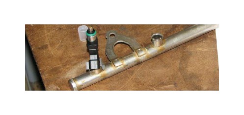
NOTE: Steps 117-119 pertains to 2007-08 Expedition/ Navigator vehicles only. Disregard otherwise and proceed to Step 117.
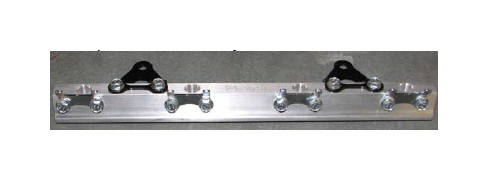
117. Install the supplied anti-rotation and mounting brackets on the supplied fuel rails using the M6 x 12mm bolts supplied in Bag #6. Note that the mounting brackets should be oriented so that the fuel rails will be installed lower than the bolt holes and the anti-rotation brackets should point down and away from the manifold.
118. Apply a small amount of lube to the O-ring of each fuel rail fitting. Install the supplied 180° swivel inlet fitting on the front provision of the driver side fuel rail and the supplied plug on the front provision of the passenger side rail. Install the two straight crossover fittings on to the rear
119. Apply a small amount of lube to each injector and insert them into the injector provisions in the fuel rails. Install the fuel crossover line on the two straight fittings and the fuel inlet line on the black inlet fitting.
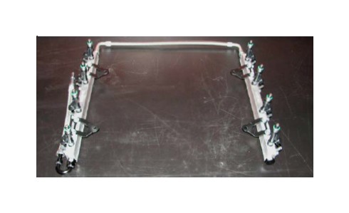
120. Install the fuel rail assembly onto the supercharger with the crossover line at the back. Line up the fuel injectors with their respective provisions then push down on the rails until all the injectors are fully seated. Use the allen bolts supplied in Bag #2 to secure the mounting brackets to the supercharger.
121. Attach the eight fuel injector electrical connectors to their respective injectors.
NOTE: 2007-08 Expeditions/Navigator need to disregard Step 122 as the use of the supplied fuel supply hose is not required. These applications simply need to reconnect the factory fuel supply hose onto the factory fuel rail.
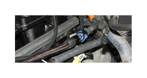
122. Push the fuel supply hose onto the fitting on the supplied fuel inlet line until it clicks into place then depress the blue lock clip to secure it.
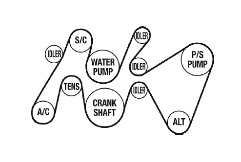
123. Route the serpentine belt according to the diagram below. Insert a breaker bar into the tensioner and apply pressure to slide the belt onto the final pulley.
124. Remove the two rear strut tower nuts on the passenger side. Lift the clip holding the nearby cable housing until it separates from the fender.
125. Mount the intercooler reservoir to its mounting bracket using the M6 x 16mm bolts supplied in Bag #5. Attach the molded Reservoir to Pump hose to the lower fitting of the reservoir; it must be routed down and around the radiator on the passenger side .Secure the hose with the supplied hose clamp.
126. Install the intercooler reservoir so that the bracket is on the strut tower studs. Reinstall the strut tower nuts and torque them to 30 ft-lbs.
127. Install the Supercharger to Reservoir hose between the intercooler reservoir and the passenger side of the supercharger and secure both ends with the hose clamps
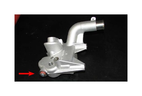
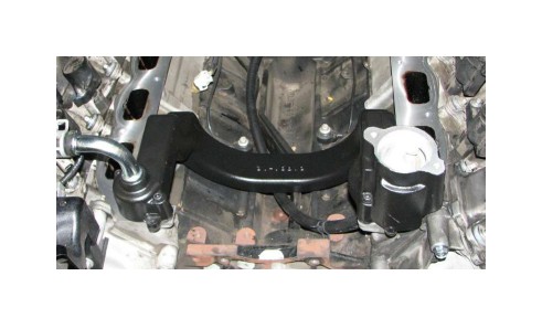
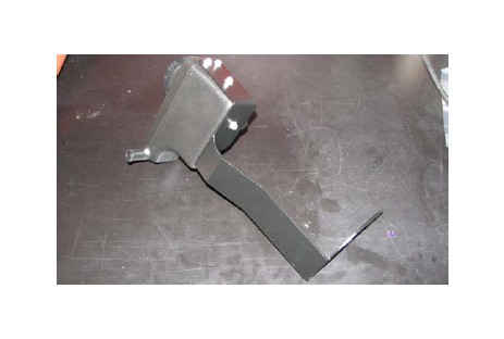
128. Install the water pump into the water pump bracket so that the pump outlet will point up when installed and the pump inlet points toward the passenger side fender. Secure the water pump to the bracket using the strap and the M8 x 30mm bolt supplied in Bag #5.
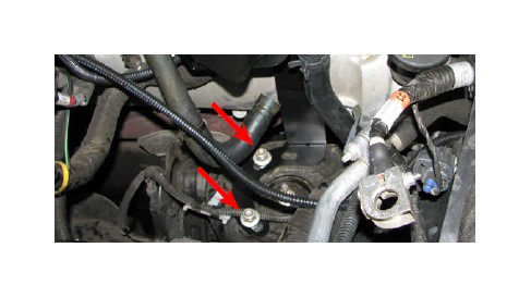
129. Identify the mounting holes on the water pump bracket then hold the bracket in place behind the bumper, on the passenger side, to identify the inner frame horn nut and bumper beam bolt.
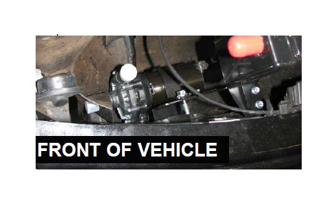
130. Remove the fasteners previously identified, install the water pump bracket then reinstall the nut and bolt.
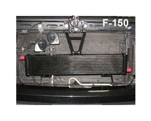
(Customers installing the Supercharger on a F-150, follow steps 131 - 135 only)
131. Loosely install the passenger side heat exchanger bracket (the one with 4 holes) to the top of the water pump bracket with the M6 x 16mm bolts supplied in Bag #5.
132. Remove the bolt behind the bumper on the driver side. Loosely install the driver side heat exchanger bracket (the one with 3 holes) using the stock bolt.
133. Mark the location of the hood latch then remove the two bolts that retain the hood latch. Using the stock bolts, loosely install the upper heat exchanger bracket over the hood latch.
134. Install the heat exchanger by lining up the mounting holes with the provisions on the mounting brackets and loosely installing the M6 x 16mm bolts supplied in Bag #5.
135. Once the heat exchanger has been lined up, tighten all of the bracket and mounting bolts.
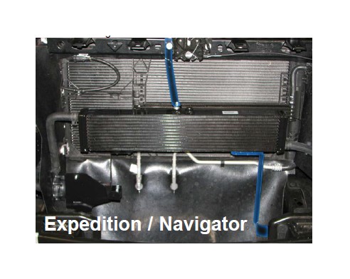
(Customers installing the Supercharger on an Expedition / Navigator, follow steps 136 - 140 only)
136. Loosely install the passenger side heat exchanger bracket (the one with 4 holes) to the top of the water pump bracket with the M6 x 16mm bolts supplied in Bag #5.
137. Remove the bolt behind the bumper on the driver side. Loosely install the driver side heat exchanger bracket using the stock nut.
138. Mark the location of the hood latch, loosen the passenger side bolt. Using the stock bolt loosely installing the upper heat exchanger bracket over the passenger side hole of the hood latch.
139. Install the heat exchanger by lining up the mounting holes with the provisions on the mounting brackets and loosely installing the M6 x 16mm bolts supplied in Bag #5 of kit #1583
140. Once the heat exchanger has been lined up, tighten all of the mounting bolts.
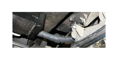
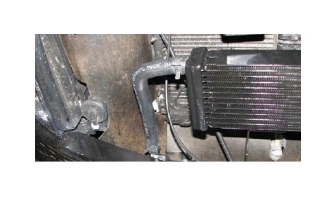
141. Route the Heat Exchanger to Supercharger hose: from the top of the engine bay, down towards the driver side headlight, around the front of the radiator, and attach it to the heat exchanger outlet fitting. Secure the fitting with a hose clamp supplied in Bag #5.
142. Route the molded hose from the bottom of the intercooler reservoir to the water pump inlet. Note the location where it intersects with the passenger side radiator shroud and make a small incision in the shroud. Feed the hose through the incision and attach it to the water pump inlet, securing the fitting with a hose clamp supplied in Bag #5.
143. Mount the Water Pump to Heat Exchanger hose on the water pump outlet and heat exchanger inlet and secure the fittings with hose clamps supplied in Bag #5.
144. Attach water pump harness connector to the pump.
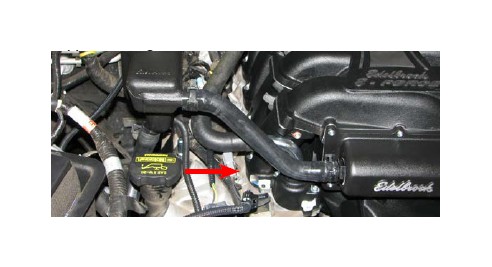
145. Connect the purge solenoid hose to the lower straight fitting, behind the throttle body flange, on the air inlet, next to the thermostat housing.
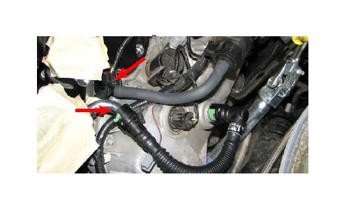
146. Connect the 90° end of the driver side PCV hose to the valve cover fitting. Connect the straight end to: the upper, 90° fitting, behind the throttle body flange, on the air inlet, next to the thermostat housing.
147. Install the Heat Exchanger to Supercharger hose to the fitting on the front of the supercharger then secure it with a hose clamp supplied in Bag #5.
148. Install the stock thermostat, O-ring and housing on the new water crossover and install the stock bolts.
NOTE: The following fan installation procedure only applies to 2009 trucks equipped with a clutch fan. 2010 trucks equipped with an electric fan should skip ahead to Step #161.
149. Reinstall clutch fan.
150. Use a cut-off wheel to trim the bottom, driver side of the radiator fan shroud as shown to clear the alternator.
151. Reinstall the fan shroud using stock hardware.
152. Clip the power steering hose on the driver side to the top of the radiator.
153. Reinstall the stock bolt that retains the power steering reservoir.
154. Reconnect the clutch fan control plug and slide the connector back on to its bracket.
155. Install the four stock bolts that hold the fuse box in place.
156. Reinstall the stock upper radiator hose between the thermostat housing and radiator and secure it with the stock hose clamps.
157. Remove the plastic sheet from the supercharger air inlet and install the throttle body O-ring supplied in Bag #1, on to the air inlet flange.
158. Install the stock throttle body onto the inlet flange with the stock bolts so that the TIPS is on top.
159. Attach the ETC Extension and TIPS connectors to the throttle body and connect the other end of the ETC Extension to the stock ETC harness connector.
160. Install the supplied air filter into the stock airbox.
161. Use a T20 Torx driver to remove the stock MAF sensor from the air box cover and install the supplied MAF sensor in its place.
162. Fully seat the supplied air filter in the air box then reinstall the air box cover. Do not latch the air box cover at this time.
163. Insert the silicone elbow between the throttle body and the MAFS housing and secure it with the supplied worm clamps. The best way to do this is to put the elbow on the throttle body first, then tilt the air box cover back and work the elbow on to the cover outlet as you tilt it back down. Latch the cover closed when you’re done.
164. Attach the ACT / MAF Jumper to the new MAF sensor and the O.E. MAFS connector, then connect it to the ACT sensor at the top of the supercharger. NOTE: 2012 & 2013 Navigator use harness 37-6622 included in kit.
165. Install passenger side PCV hose between the passenger side valve cover and the fitting at the side of the silicone elbow.
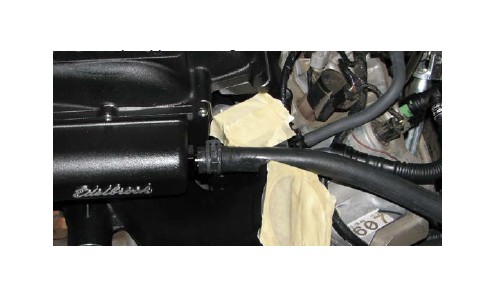
166. Install the supplied hose onto the brake booster barb and route it to the fitting at the front of the air inlet and secure the fittings with hose clamps supplied in Bag #1.
167. Verify that the coolant petcock is closed, then refill the coolant system.
168. Fill the intercooler system with a 50/50 blend of water and coolant poured into the recovery tank. Fill the tank until the water level is roughly 1” from the top of the threaded neck.
169. Reinstall the battery terminal. Turn the ignition key to the ‘ON’ position but do not start the engine.
170. Verify that water is flowing briskly through the recovery tank, then install the cap. If water is not flowing, turn the key off and on again to bleed the system. Turn key off when finished.
CAUTION: The power steering system must be filled and bled prior to starting the vehicle. Failure to do so may cause premature power steering pump failure. For additional information on power steering system bleeding, please refer to your service manual or contact your dealer.
It is highly recommended to use a vacuum source to purge the air out of your power steering system. If a vacuum source is not available during the time of installation, Steps 171-174 can be used as the minimum requirements for bleeding the power steering system. The assistance from another person is required to successfully perform Steps 171-174.
171. Raise the front wheels off the ground with a service lift, or equivalent, and fill the power steering reservoir with power steering fluid to the “full cold” level.
172. Turn the Key to the “Acc” or “On” position (DO NOT START ENGINE). Turn the steering wheel slightly to the left, approximately to the 11 o’clock position, (do not turn until lock) and have an assistant top off the fluid as soon as the fluid level drops.
173. Leaving the reservoir cap off, slowly and smoothly turn the steering wheel back and forth from the 11 o’clock and 1 o’clock position (do not go lock to lock) until the fluid level drops in the reservoir. Have the assistant fill the reservoir as soon as the fluid level drops. This may take a few minuets to completely purge the air in the system.
NOTE: If signs of bubbles are present, recheck all connections and repeat Step 173.
174. Reinstall the reservoir cap when all air has been purged from the system.
NOTE: Once the vehicle is able to start, it is recommended to remove the reservoir cap and let the engine idle while turning the steering wheel back and forth per directions in Step 173. This will help purge any air that may be trapped in the power steering system. Refill fluid as need and replace cap once finished.
If Steps 171-174 were used to bleed the power steering system, it is highly recommended to use a vacuum source to finalize the bleeding process.
If you have yet to flash your ECU, then proceed with Steps 175-187, otherwise disregard them.
175. Confirm that you have the latest calibration by checking the Edelbrock website (http://www.edelbrock. com/automotive_new/mc/superchargers/software-tech. shtml ) and entering your serial number in the search field. Once you have found the latest tune on the site, power on the programmer, press the left arrow and select the Device Info option. Scroll down to Tune Version and compare that number to the one on the site. If they are different, download the new calibration as instructed on the website.
176. Connect the supplied PCM cable on the handheld programmer to the OBD-II connector located below the steering wheel in the passenger compartment.
177. Use directional pad to highlight Program Vehicle option and press Select button.
178. Use directional pad to highlight Preprogrammed Tune option and press Select button.
179. Read disclaimer then press Select to continue. 180. Verify ignition is in the ‘Key On’ position but that the engine is not running then press Select.
181. Use directional pad to highlight your vehicle and transmission combination then press Select.
182. Use directional pad to highlight Begin Program then press Select.
183. Five separate operations will take place during this step. Completion of each operation will cause the progress bar to reset to zero.
DO NOT unplug the programmer until prompted.
184. Turn the vehicle off when prompted to do so by the handheld programmer.
185. Read parting message from programmer then press Select to continue.
186. Unplug the programmer cable from the OBD-II port.
187. If you have access to a diagnostic scan tool, run a ‘Key On, Engine Off’ test to verify that all connectors are properly installed, otherwise move on to the next step.
188. Start the vehicle and verify a smooth idle. If you are using a diagnostic scan tool, run a ‘Key On, Engine Run’ test.
189. Carefully inspect the fuel rail and fuel hose fittings for any leaks. Shut off the engine immediately and make repairs as necessary before continuing if any leaks are detected.
190. Verify that the power steering system is fully bled using the NOTE in Step 173. NOTE: If Steps 171-174 were used to bleed the power steering system, it is highly recommended to use a vacuum source to finalize the bleeding process.
191. Check all fluid levels including engine oil before operating vehicle.
Congratulations on the installation of your new Edelbrock E-Force Supercharger System. If you have any questions, please call our Technical Support hotline and one of our technicians will be happy to assist you.