FREE 1 to 3-Day Delivery on Orders $149+ Details
How to Install Daystar 2 in. Comfort Ride Front Leveling Kit (10-14 Raptor) on your Ford F-150
Tools Required
- Pry Bar
- Small Sledge Hammer
- 30mm wrench or deep socket
- 26mm wrench or deep socket
- 21mm wrench or deep socket
- 8mm wrench
- 10mm wrench
- Heavy Duty Jack
- Jack Stands

Shop Parts in this Guide
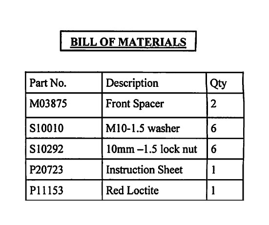
Ford SVT Raptor 1.5" Leveling Kit Instructions
Your new Daystar Leveling kit will allow the installation of 37" tires. After completion make sure to have your vehicle aligned to factory specs.
The tools needed for installation are on the last page. A list of parts in the kit are under the BOM, verify that you have all parts prior to installing your new leveling kit. Make sure you have all of the proper tools and understand these directions before pro-ceeding. Place Vehicle on level ground. Be sure that the wheels are blocked and the vehicle is in park.
Measuring Vehicle
You will want to measure your vehicle before and after installa-tion in the same area. We recommend taking your measurements from the center of your wheel to the bottom of your fender well, and from the ground to the bottom of your bumper. Once you have pre-measured your vehicle proceed to raising the truck.
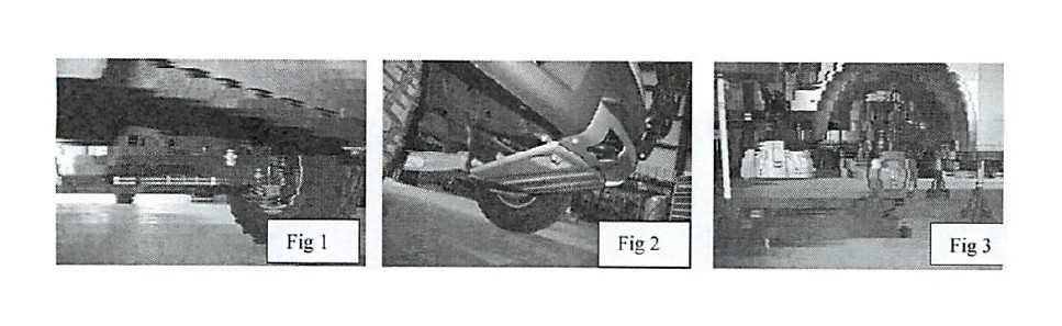
Raising your Vehicle-Fig 1-3
Your Svt Raptor is fitted with two front skid plates, if you are using a jack and jack stand's we recommend that you remove these two skid plates and raise the vehicle from the front cross member. Place your Jack stands' underneath the frame rails just behind the front tires.
Disassembly
1 . Begin by removing your tires and wheels. Once they are re-moved, place a jack under the lower control arm for support.
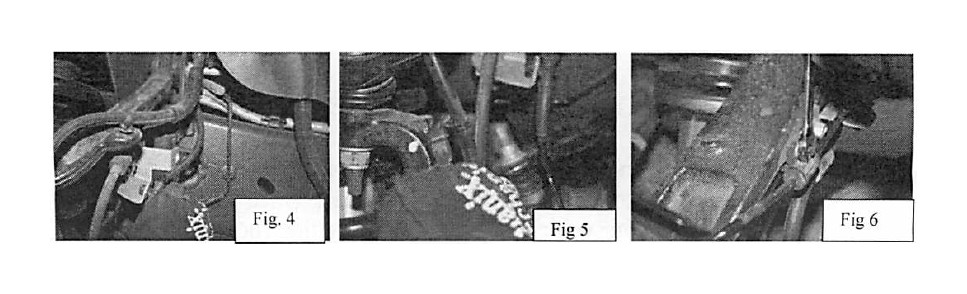
2. Loosen and remove the brake line clamp that is located at the strut bucket and the two clamps that hold the ABS line and Hub vent that are on the spindle. Also carefully remove the two Christ-mas tree push-in clips that are located on the upper control arm, and the spindle (using a pair of side cutters, apply light pressure and slowly pry them out, failure to be careful will result in these snapping off) Fig 4-6
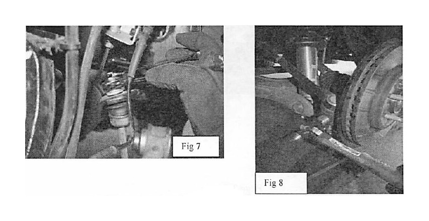
3. Loosen and remove the sway bar nut that is attaching the end link to the sway bar. Loosen and remove the outer tie rod; you will want to leave the nut on by a couple of threads, strike the side of the tie rod mount to free it, then remove the nut the rest of the way. Fig 7-8
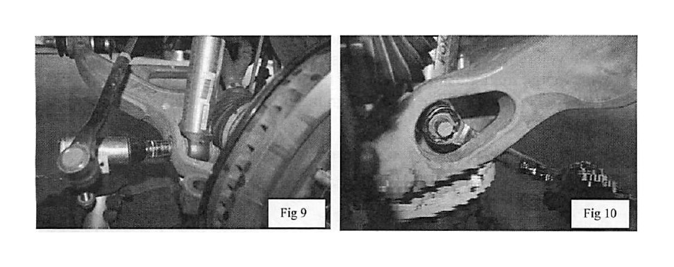
4. Loosen and remove the lower strut bolt. Fig 9-10
5. Loosen the upper ball joint nut but leave the nut in place by a couple of threads. Place pressure to the lower control arm using your jack. With the upper ball joint nut loose, strike the knuckle where the ball joint sits to loosen it from its mount. You will know when the ball joint is loose when it pops. Remove the ball joint nut and swing the upper control arm away from the knuckle.
6. Once the upper control arm and the knuckle are free from each other, support the knuckle and keep it from flopping around using a ratchet strap. This will help to keep the CV shaft in place. It is im-portant to not spin the rotor or the CV shaft while the CV shaft is at this angle, use caution to not rotate it!
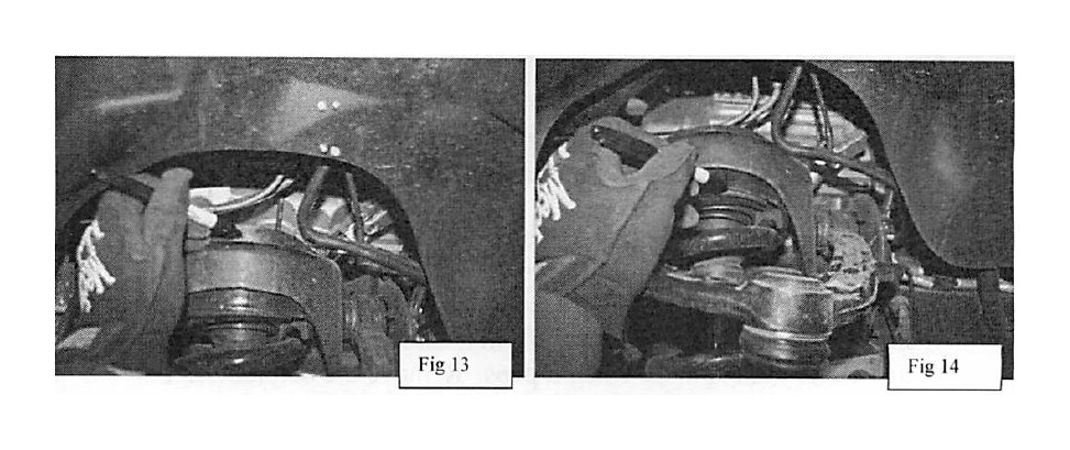
Strut Removal-Fig 13-14
7. Prior to removing the upper strut bolts you will want to make a reference line on the top cast plate and the strut plate (note that when you remove the strut there is a second cast plate and you will want to mark this in reference to the line made on the strut plate.) These lines will help to realign the strut plates when you re-assemble your Strut and Spacer.
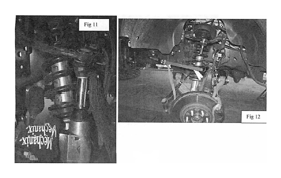
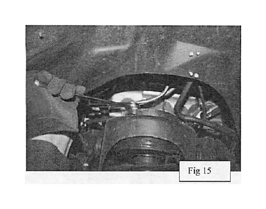
8. With the plates marked remove the three nuts that are holding the strut in place. With these removed you will now be able to remove the strut. -Fig 15
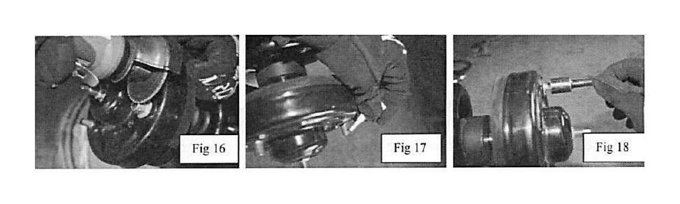
Trimming the Studs and Installing Stud Extenders-fig 16-18 9. The factory studs on the strut will need to be trimmed down. Start by re-installing the factory nuts on the studs and then run them all the way down until they bottom out against the strut plate. Next, cut the factory studs (using a cut off wheel or hack saw) just above the top of the factory nuts (do not cut into the nut). With the cutting complete, remove the nuts and clean up the threads if necessary. Next, apply red loctite to the factory studs and install the supplied stud extenders and tighten to 25 lb-ft.
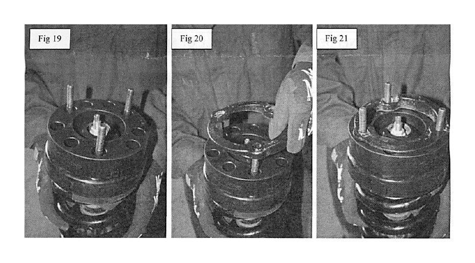
Spacer Installation-Fig 19-21
10. With the stud extenders installed and torqued, you are now ready to install the spacer. Place the supplied Daystar spacer on the strut. Next, the stock cast plate will go on top of the Daystar spacer; make sure to line up the marks you had previously made. With the spacers and plates installed and aligned, place the upper end of the strut back in the frame bucket. Position the factory top strut plate over the studs (aligning it with the other lines made) and secure the strut in the bucket using the factory nuts. Do not tighten the nuts at this time.
11. Once the Strut is back in the strut bucket you will repeat the steps above in reverse to install the strut back into the vehicle. Be sure to tighten the upper strut nuts once the lower end of the strut and control arm are reconnected.
12. When the strut assembly, upper control arm, outer tie rod end, and sway bar are back into place tighten them to factory torque specs. Repeat these steps for the opposite side of the vehicle.
13. Reinstall the tire and wheels, remove the jack stands and place the vehicle back on the ground. Note that the vehicle will need to settle, you will want to drive the truck for a short distance to let it settle.
14. After driving the truck place it back to where you originally took your measurements and measure the truck. Recheck that all bolts are tight and that there is no interference with other suspen-sion components.
15. Have a professional wheel alignment performed. The vehicle should be aligned to factory specifications.
16. Double-check all fasteners for proper torque after 500 miles and periodically thereafter.