FREE 1 to 3-Day Delivery on Orders $149+ Details
How to Install Fabtech 3.5 in. Spindle Lift Kit w/ Shocks on your Silverado
Installation Time
3 hours
Tools Required
- FLOOR JACK
- JACK STANDS
- ASSORTED METRIC AND S.A.E SOCKETS, & ALLEN WRENCHES
READ ALL INSTRUCTIONS THOROUGHLY FROM START TO FINISH BEFORE BEGINNING INSTALLATION! IF THESE INSTRUCTIONS ARE NOT PROPERLY FOLLOWED, SEVERE FRAME OR UPPER CONTROL ARM DAMAGE MAY RESULT TO THE VEHICLE.
CHECK ALL PARTS INCLUDED IN THIS KIT TO THE PARTS LIST ABOVE BEFORE BEGINNING INSTALLATION OF THE KIT. IF ANY PIECES ARE MISSING, CONTACT FABTECH AT 909-597-7800.
OEM WHEELS AND TIRES CAN NOT BE USED AFTER THE INSTALLATION OF THIS KIT. A LARGER TIRE CANNOT BE INSTALLED ON THE OEM WHEELS. WE RECOMMEND AFTER MARKET WHEELS - 17 X 8 WITH A 5.0 BACK SPACE. TIRE – 33 X 12.5 X 17.
VEHICLES THAT WILL RECEIVE OVERSIZED TIRES SHOULD CHECK BALL JOINTS, TIE RODS ENDS AND IDLER ARM EVERY 2500-5000 MILES FOR WEAR AND REPLACE AS NEEDED
SUSPENSION SYSTEM WILL NOT WORK ON VEHICLES EQUIPPED WITH FACTORY AUTO RIDE SUSPENSION
INSTRUCTIONS:
1. Disconnect the negative terminal on the battery. Jack up the front end of the truck and support the frame rails with jack stands. NEVER WORK UNDER AN UNSUPPORTED VEHICLE! Remove the front tires.
2. Starting on the driver side of the truck, remove the bolt attaching the brake line tab to the spindle. Remove the two bolts securing the brake caliper bracket to the spindle, separate the brake caliper from the spindle and tie it up out of the way. DO NOT LET THE CALIPER HANG BY THE BRAKE LINE!
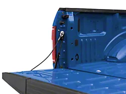
3. Follow the wheel speed sensor wire from the hub to the frame rail. Separate the wire from the upper control arm and separate the connector at the spindle. SEE PHOTO BELOW
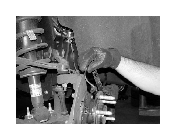
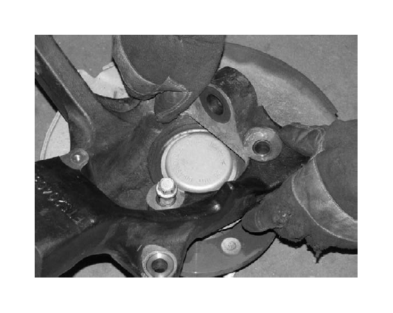
4. Remove the nuts securing the tie rod, upper and lower ball joints to the spindle. Separate all three joints from the spindle and remove the spindle from the control arms. Remove the three bolts securing the wheel bearing assembly to the spindle, noting the position of the hub and dust shield in the spindle for reassembly. SEE PHOTOS BELOW
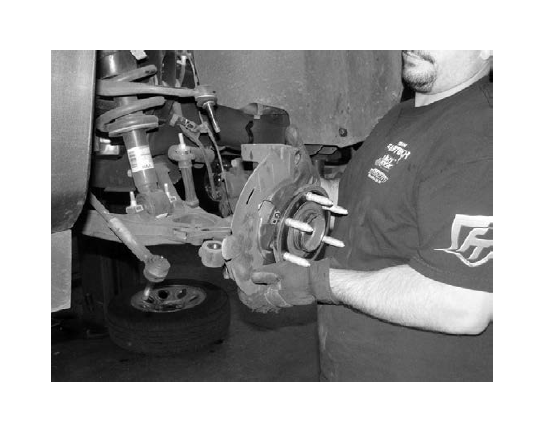
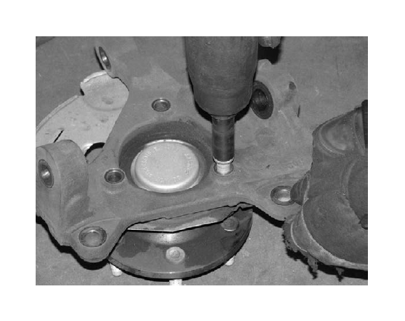
5. Locate the spindle marked FTS20463D. Install the Factory dust shield and hub assembly into the new Fabtech spindle. Apply several drops of the supplied thread locking compound to the three original spindle hub bolts and torque to 160 ft-lbs. SEE PHOTO BELOW
6. Locate the steering knuckle FTS20463D and attach the lower control arm to the spindle using the stock hardware and torque to 70 ft-lbs. Attach the upper control arm to the new knuckle using the factory hardware and torque to 30 ft- lbs.
7. Reinstall the brake rotor, caliper and wheel speed sensor. Torque caliper bolts to 100 ft-lbs.
8. Locate FT20277 outer tie rods. Loosen the jam nut and remove the factory outer tie rods and discard, leaving the factory jam nut on the inner tie rod. Install the new outer tie rod onto the inner tie rod until it makes contact with the jam nut. Attach new tie rod end to the knuckle with the supplied nut and torque to 60 ft-lbs. (This is just a starting point. A final alignment must be performed upon completion of suspension system).
SEE PHOTOBELOW
9. Repeat steps 2-8 on the passenger side of the vehicle.
10. Install the front tires and torque the wheel lugs to factory specifications. Set the truck back on the ground. WHILE TURNING THE STEERING WHEEL FULLY IN EACH DIRECTION, MAKE SURE THERE IS AMPLE CLEARANCE BETWEEN THE WHEELS, TIRES, CONTROL ARMS, BRAKE LINES AND ABS WIRES.
If installing FTS21088, perform the following steps:
11. Disconnect the negative terminal on the battery. With the u-bolts removed and the rear axle clear of the leaf spring, make sure the block will fully seat onto the leaf spring and the spring pad of the rear axle housing with the wide end of the block to the rear of the vehicle. On the leaf spring make sure the center pin head will seat fully into the hole in the block, allowing the top surface of the block to rest against the leaf spring. If the hole in the block is not large or deep enough, drill it out to fit the center pin. Add 1/16” or 0.063” to the center pin diameter, and enlarge the hole to this size. Do not enlarge the hole more then that measurement.
12. If the pin in the lift block cannot fully seat into the rear axle spring pad, you will need to shorten the block center pin. To shorten the block center pin, use a hand grinder or sander to remove only as much material as is necessary.
13. Test fit the block after all modifications and complete the installation. Please notify Fabtech Motorsports on any modifications that were made during the installation of this block kit.
14. Check the wheel alignment and set to the factory specifications. Readjust head lights.