 FREE 1 to 3-Day Delivery on Orders $149+ Details
How to Install Brembo GT 6-Piston Front Brake Kit - 15 in. Cross Drilled - Black (2017 Raptor) on your Ford F-150
Tools Required
- Wrenches
- Torque Wrench
- Pliers
- Screwdriver
- Spacer
- Piston retractor
- Dial Indicator with magnetic base
- Brake Fluid Collection tank
- Jack and Jack Stands
- Clean cloth
- Solvent for Cleaning
- Brake Fluid
- Vehicle service manual

Shop Parts in this Guide
- Brembo GT Series 6-Piston Front Big Brake Kit with 15-Inch Cross Drilled Rotors; Black Calipers (17-20 F-150 Raptor)
- Brembo GT Series 6-Piston Front Big Brake Kit with 15-Inch Cross Drilled Rotors; Red Calipers (17-20 F-150 Raptor)
- Brembo GT Series 6-Piston Front Big Brake Kit with 15-Inch Cross Drilled Rotors; Silver Calipers (17-20 F-150 Raptor)
- Brembo GT Series 6-Piston Front Big Brake Kit with 15-Inch Type 1 Slotted Rotors; Black Calipers (17-20 F-150 Raptor)
- Brembo GT Series 6-Piston Front Big Brake Kit with 15-Inch Type 1 Slotted Rotors; Red Calipers (17-20 F-150 Raptor)
- Brembo GT Series 6-Piston Front Big Brake Kit with 15-Inch Type 1 Slotted Rotors; Silver Calipers (17-20 F-150 Raptor)
- Brembo GT Series 6-Piston Front Big Brake Kit with 15-Inch Type 3 Slotted Rotors; Black Calipers (17-20 F-150 Raptor)
- Brembo GT Series 6-Piston Front Big Brake Kit with 15-Inch Type 3 Slotted Rotors; Red Calipers (17-20 F-150 Raptor)
- Brembo GT Series 6-Piston Front Big Brake Kit with 15-Inch Type 3 Slotted Rotors; Silver Calipers (17-20 F-150 Raptor)
- Brembo GT Series 8-Piston Front Big Brake Kit with 16.20-Inch Cross Drilled Rotors; Black Calipers (17-20 F-150 Raptor)
- Brembo GT Series 8-Piston Front Big Brake Kit with 16.20-Inch Cross Drilled Rotors; Red Calipers (17-20 F-150 Raptor)
- Brembo GT Series 8-Piston Front Big Brake Kit with 16.20-Inch Cross Drilled Rotors; Yellow Calipers (17-20 F-150 Raptor)
- Brembo GT Series 8-Piston Front Big Brake Kit with 16.20-Inch Cross Drilled Rotors; White Calipers (17-20 F-150 Raptor)
- Brembo GT Series 8-Piston Front Big Brake Kit with 16.20-Inch Cross Drilled Rotors; Fluorescent Yellow Calipers (17-20 F-150 Raptor)
- Brembo GT Series 8-Piston Front Big Brake Kit with 16.20-Inch Type 1 Slotted Rotors; Black Calipers (17-20 F-150 Raptor)
- Brembo GT Series 8-Piston Front Big Brake Kit with 16.20-Inch Type 1 Slotted Rotors; Red Calipers (17-20 F-150 Raptor)
- Brembo GT Series 8-Piston Front Big Brake Kit with 16.20-Inch Type 1 Slotted Rotors; Yellow Calipers (17-20 F-150 Raptor)
- Brembo GT Series 8-Piston Front Big Brake Kit with 16.20-Inch Type 1 Slotted Rotors; White Calipers (17-20 F-150 Raptor)
- Brembo GT Series 8-Piston Front Big Brake Kit with 16.20-Inch Type 1 Slotted Rotors; Fluorescent Yellow Calipers (17-20 F-150 Raptor)
- Brembo GT Series 4-Piston Rear Big Brake Kit with 15-Inch Cross Drilled Rotors; Black Calipers (2017 F-150 Raptor)
- Brembo GT Series 4-Piston Rear Big Brake Kit with 15-Inch Cross Drilled Rotors; Red Calipers (2017 F-150 Raptor)
- Brembo GT Series 4-Piston Rear Big Brake Kit with 15-Inch Cross Drilled Rotors; Silver Calipers (2017 F-150 Raptor)
- Brembo GT Series 4-Piston Rear Big Brake Kit with 15-Inch Type 1 Slotted Rotors; Black Calipers (2017 F-150 Raptor)
- Brembo GT Series 4-Piston Rear Big Brake Kit with 15-Inch Type 1 Slotted Rotors; Red Calipers (2017 F-150 Raptor)
- Brembo GT Series 4-Piston Rear Big Brake Kit with 15-Inch Type 1 Slotted Rotors; Silver Calipers (2017 F-150 Raptor)
- Brembo GT Series 4-Piston Rear Big Brake Kit with 15-Inch Type 3 Slotted Rotors; Black Calipers (2017 F-150 Raptor)
- Brembo GT Series 4-Piston Rear Big Brake Kit with 15-Inch Type 3 Slotted Rotors; Red Calipers (2017 F-150 Raptor)
- Brembo GT Series 4-Piston Rear Big Brake Kit with 15-Inch Type 3 Slotted Rotors; Silver Calipers (2017 F-150 Raptor)
Safety and Liability Information
Warning:
Installation of any component or system should only be performed by persons experienced in the installation and proper operation of disc brake systems. These are high performance components which will not function as intended if misused or if not installed properly to the correct specifications. It is the responsibility of the individual installing any brake component or system to determine the suitability of the component or system for that particular application.
The brake system is a safety device;
Personnel performing any replacement or maintenance operations must be competent and certified
Wheel fitment
Brembo recommends:
> The tires external diameter must equal that defined by the vehicles manufacturer
> If bigger tires are used, make sure that their rotation is not hampered under all conditions of use of the vehicle
> Install the Gran Turismo Brake System on both sides
Lack of compliance with these preliminary recommendations can result in an incorrect reading of the vehicles speed, or, in the worst case, it can seriously damage the tires structure and affect vehicle safely.
Due to the increased disc diameter and caliper width of the Brembo Gran Turismo Brake Systems, it may be necessary to use different wheels or wheel spacers.
Before starting the replacement procedure, make sure that the spare parts used for replacement are suitable to the make and model of the vehicle.
Detailed brake cross sections are available by contacting Brembo or by visiting our website.
Disc Rotation Direction
It is a popular misconception that the slots or drillings in a disc determine the direction of rotation. In truth, for an internally vented disc, the geometry of the vanes dictates the direction of rotation. There are three vane types in use:
1.Straight
2.Pillar vane (comprised of many small posts)
3.Curved vaneThe first two vane types are non-directional, and can be used on either side of the vehicle. The curved vane disc, however, is directional. A curved vane disc must be installed with the vanes running back from the inside to outside diameters in the direction of rotation. Please see figure.
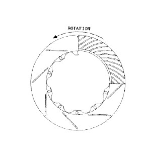
Orienting the disc in the manner creates a centrifugal pump. The rotation of the disc causes air to be pumped from the center of the disc, through the vanes, and out through the outside diameter of the disc. This greatly enhances the disc's ability to dissipate heat.
Additionally, all of Brembo's slotted discs are directional as well, regardless of the vane geometry. The discs should be installed such that the end of the slot nearest the outer edge of the disc contacts the pad first.
Caliper Orientation
Brembo calipers are directional, due to the use of differential piston sizes. The leading pistons are smaller in diameter in order to combat uneven wear of the brake pads. Upon close inspection of the caliper, you will find a small arrow cast in place that denotes the direction of the disc rotation. Additionally, when mounted on the vehicle, the bleed screws must be at the top of the caliper.
Floating Disc
Brembo two-piece disc assemblies utilize a floating disc. The mounting system of the disc is designed to allow a specific amount of float in both the radial and axial directions. Brembo has engineered special springs that are used on every other fastener in order to slightly preload the assemble.
This had been done to prevent excessive noise from the system during street use, while still maintaining the benefits of a floating disc. These springs can be seen when looking at the backside of the disc. Those fasteners which do not have springs installed will not firmly clamp the bell and disc together, this is as it should be. The small screws on the backside of the disc are properly torques during assembly and utilize thread lock compound to prevent loosening. They must NOT be tightened further.
Brake Pads
The brake pads that are provided with Brembo brake systems are high performance pads that offer a very board temperature and performance range. The pads are effective at cold temperature as well as the higher temperatures seen during performance driving. These pads are suited to high performance street driving. If interested in using alternative friction materials, please contact Brembo for recommendations. Please notes that the that the brake pads supplied with the Gran Turismo Kits do not have Noise generators to alert when the pad needs to be replaced. Pads must be inspected periodically to ensure that disc damage does not result due to overly worn pads. Pads are considered fully worn when the friction material reaches 2mm in thickness.
Do Not Remove Disc from Bell
Contact Brembo for instructions on the proper procedures for disc replacement
Do Not Disassemble Calipers
Di not attempt to loosen or tighten the bolt securing the caliper halves together
Do Not Remove Caliper Studs
Do not attempt to remove the caliper studs from the brackets
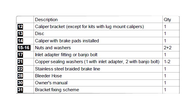
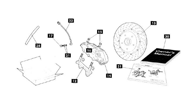
Gran Turismo Brake System Components List
The following is a list of components which are included in each Gran Turismo System box, and includes all components for each corner of the vehicle.
Lifting and Supporting Vehicle
> Slightly loosen wheel nits or bolts before lifting the vehicle
> Carefully lift the vehicle using the lift points indicated in the vehicles manufacturer's owner or service manual
> Support the vehicle using jack stands, once again following the vehicle manufacturer's recommendations
> Remove the wheel
Caution
Do not rely on the jack to support the vehicle while performing the following operations.
Failure to comply with the vehicle manufacturer's guidelines in lifting and supporting the vehicle can lead to injury, death, and / or property damage.
Bypassing Brake Pad Wear Sensor
This procedure is only applicable to the vehicles equipped with an electronic pad wear indicator. If your vehicle is not so equipped, skip to original component removal.
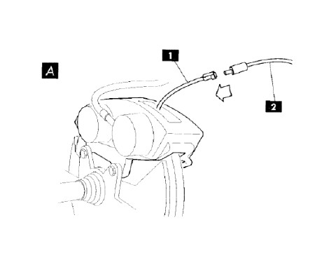
• (A) Disconnect the wear indicator cable (1) from the vehicle harness(2).
• Insert the key into the ignition and turn to the engine on position without starting the engine
> If the pad wear indicator lamp illuminates on the instrument cluster, perform the following steps; otherwise turn the ignition key to the engine off position and secure the vehicle harness so that it is out of the way, and wont become stretched or entangled during suspension and steering movement
> This is best accomplished using "zip" ties.
• Cut the wear indicator cable (1) 3-4 cm from the connector (3)
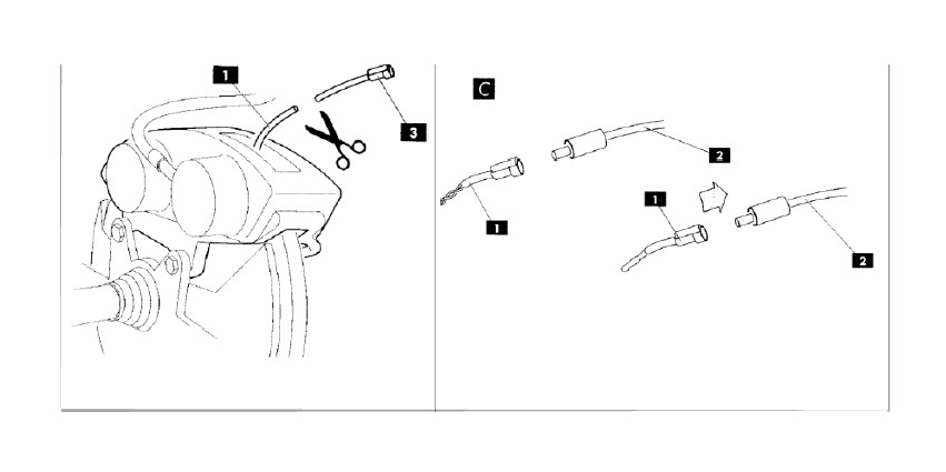
• Connect the two ends of the cable(1)and insulate using electrical tape or heat shrink tubing.
• Reconnect the cable(1)to the vehicle harness(2)
• Turn the ignition key to the engine on position without starting the engine
• Ensure that the pad wear indicator lamp on the instrument cluster remains off. If it is still illuminated, re-check the electrical connections from the previous steps
> Secure the harness (2)so that it is out of the way, and wont become stretched or entangled during suspension and steering movement
> This is best accomplished using "zip" ties.
Original Component Removal
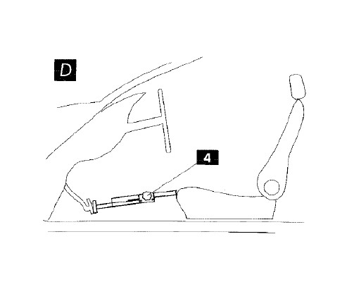
Caution:Use caution to ensure that brake fluid does not come in contact with any painted surfaces. If brake fluid should contact these surfaces, wash them immediately or damage could result.
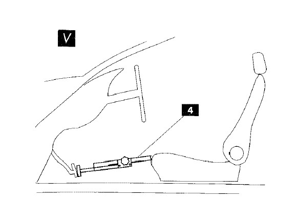
(D)If the vehicles master cylinder is not equipped with an anti-drain back valve, the brake pedal can be slightly depressed to prevent excessive brake fluid leakage. This will move the Master cylinder piston past the orifice which allows brake fluid to drain from the reservoir. To accomplish this, either obtain assistance from another person, or place a spacer (4) between the pedal and the seat to depress the pedal 1 1/2 to 2 inches only.
Do not depress the brake pedal further.
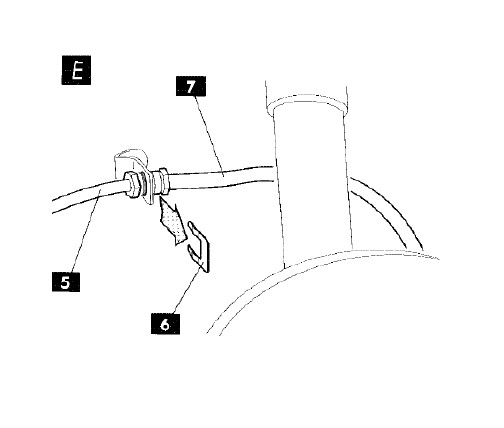
(E)Loosen the brake line fitting at the chassis end (5).
Use caution to prevent rounding the corners of the hard line hex fittings. It is strongly recommended that a line-wrench be used when tightening or loosening these connections. Have a cloth and drain pan available to catch any brake fluid which leaks out.
(E)If present, remove all retaining clips (6)from the flexible brake line (7)
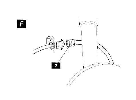
(F)Remove the brake line (7)from the chassis bracket, and any other in-line connections that it may have. The line may remain connected to the brake caliper.
(F)Use a plug to close the flexible brake line connected to the caliper(7)so that dirt is not inadvertently introduced.
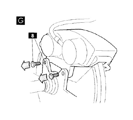
(G)Remove the caliper mounting bolts(8)fastening the caliper to the knuckle.
Remove the caliper
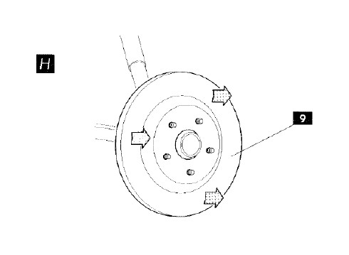
(H)Locate and remove any screws or bolts holding the original brake disc to the hub.
Remove the original disc(9)from the hub. If the disc is difficult to remove, there may be a threaded hole in the hub face of the brake disc to aid in its removal. In these cases, thread a bolt with the correct size and pitch into this hole until it pushed the disc off the hub face. In the absence of a hole of this type, or a suitable bolt, use a rubber mallet to tap the back side of the disc at several points around its circumference until it is freed from the hub face. The disc may then be removed.
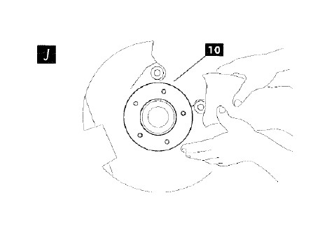
(J)Clean spece the caliper mounting surfaces(10)using a cloth moistened with solvent to remove any contaminants. If corrosion is present on these surfaces, remove with an abrasive pad or wire brush.
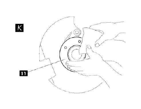
(K)Clean the disc mounting area of the hub face (11)using a cloth moistened with solvent to remove any contaminants.
If corrosion is present on these surfaces, remove with an abrasive pad or wire brush.
In many cases, the original dust / splash shield will have to be removed in order to fit the larger Gran Turismo brake disc. Test fit the Gran Turismo brake disc. If the Gran Turismo Disc cannot sit flat on the hub face and rotate freely with a minimum of 3 mm of clearance, the shield must be removed. Refer to the vehicle manufacturer's service manual for the removal procedure.
Gran Turismo Component Installation
Gran Turismo Brake Systems are supplied in two separate packages which constitute left hand and right hand brake elements, and are labeled as such. Ensure that the correct components set is used on each side of the vehicle, and do not mix components from the two separate packages.
Brembo recommends that the disc run out measurement be performed upon installation of the new disc. This is to ensure that the vehicle hub / upright / bearing is in perfect working order. If a vibration problem should be present, and this procedure has not followed due to lack of availability of the proper tools and equipment, take the vehicle to a facility capable of performing these measurements.
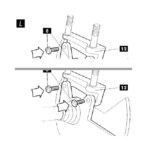
(L)If your system uses lug mount calipers, skip to step(O). Refer to the diagram included with the system for proper bracket orientation.
Install the bracket on the(12)knuckle using the bolts (8)that mounted the original caliper. If the original bolts are damaged in any way, purchase replacements from your vehicle manufacturer's parts department. In some cases, bolts are supplied with the Gran Turismo systems, and must be used for proper caliper bracket mounting. Ensure that the mounting surface of the bracket is in full contact with the mating surface on the knuckle. There must not be any interference between the bracket and the knuckle. Regardless of which bolts are used, torque to the vehicle manufacturer's specification for brake caliper mounting.
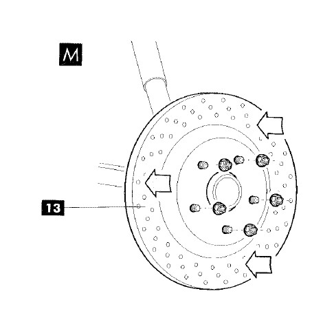
( M)Place the disc(13)onto the hub. In most cases, if there were bolts or screws holding the original disc to the hub, these features have to be duplicated in the Gran Turismo Systems. If performing the following disc runout measurement, temporarily install all of the wheel nuts or bolts. Use several washers on each bolt or stud to prevent damage to the disc bell and to prevent the nuts or bolts from bottoming before securely clamping the disc to the hub. Torque to 14 Nm (10 ft Lbs)
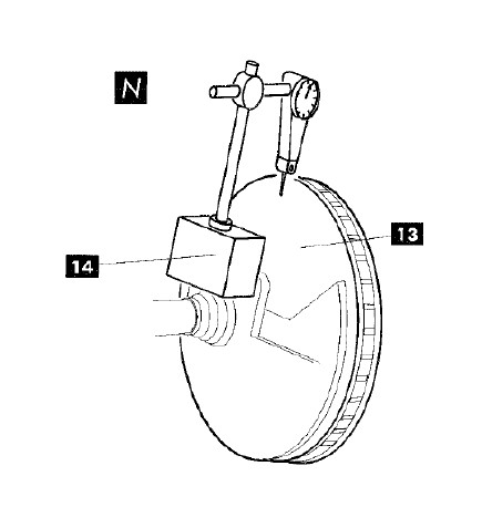
(N)Place the magnetic base for the dial indicator (14)solidly on the vehicle ensuring that it will not move during the measurement taking procedure. Place the dial indicator needle on the inboard braking surface of the disc (13)approximately 3-5mm from the outer edge of the disc. Ensure that the needle will not contact a hole or slot in the disc when rotated.
Turn the disc a full revolution. The total oscillation of the indicator should not exceed 0.07mm (0.003 inch)
If the disc run out exceeds the value, it may be possible to reduce it by indexing the disc on the hub face. However, if your vehicle utilizes bolts or screws to secure the disc to the hub, this will not be possible. In those cases where indexing is possible, repeat the above measurement for each index increment.
If the run out still exceeds the above value, the vehicle hub / upright / bearing is most likely out of specification. Consult the vehicles manufacturer's service manual for the steps needed to correct this condition.
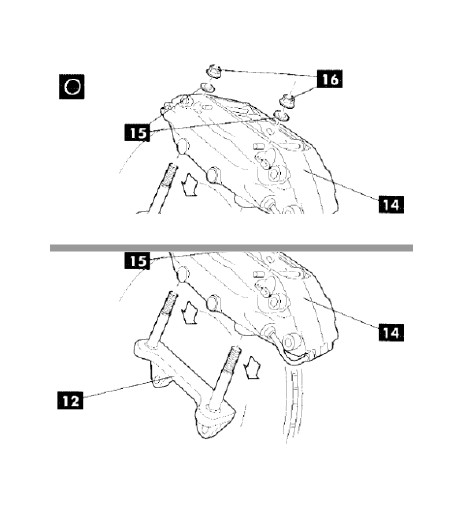
(O)Slide the new caliper(14)over the disc and the studs on the bracket (12). Install one washer (15)and one nut (16)onto each stud. These nuts are self locking and have an oval cross section, they do not require thread lock compound. Torque each nut to 115 Nm (80 ft lbs). If your system uses lug mount calipers, secure them to the knuckle using the bolts that mounted the original caliper. If the original bolts are damaged in any way, purchase replacements from your vehicle manufacturer's parts department. Torque the vehicles manufacturer's specification for brake caliper mounting.
Note:Do Not apply sealant or thread lock to any brake line connections.
Remove the threaded plastic plug from the fluid inlet on the side of the caliper.
(P)For systems supplied with an inlet adapter fitting (17), insert the short end of this fitting through the supplied copper sealing washer (21), and thread into the fluid inlet on the caliper(18). Torque fitting to 2 Nm (15 ft lbs)

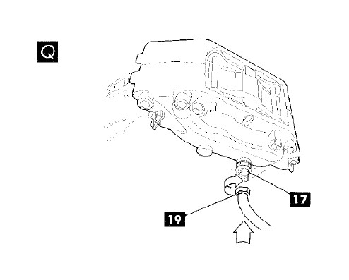
(Q)Thread the caliper end of the steel braided brake line (19)onto the inlet adapter fitting (17), leaving loose so the fitting can rotate during the following steps.
Skip to step(S)
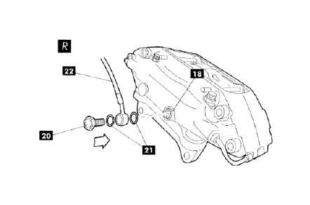
(R) For systems supplied with a banjo bolt fitting, insert the banjo bolt (20), through a copper sealing washer (21)the banjo fitting(22), and the second copper sealing washer(21). Thread the banjo bolt into the fluid inlet of the caliper (18),leaving loose, so that the fitting can rotate during the following steps.
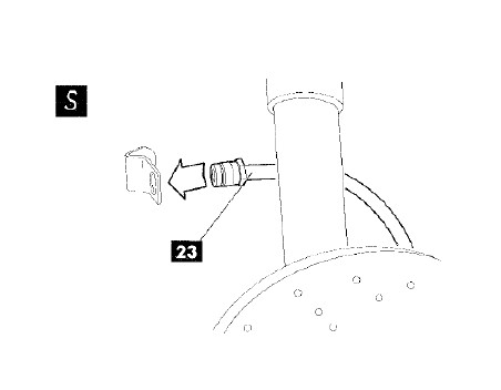
(S)Connect the brake line to any in-line connections that it may have. Insert the brake line end-fitting (23)into the frame bracket, ensuring that the lines does not become twisted.
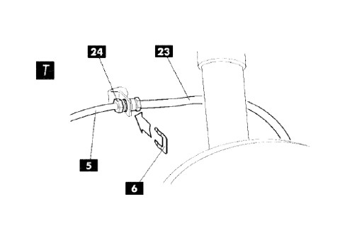
(T)reconnect the brake line(23)to the chassis hard-line(5).
Install any brake line retaining clips(6).
Tighten the fittings (24)to the vehicle manufacturer's specifications.
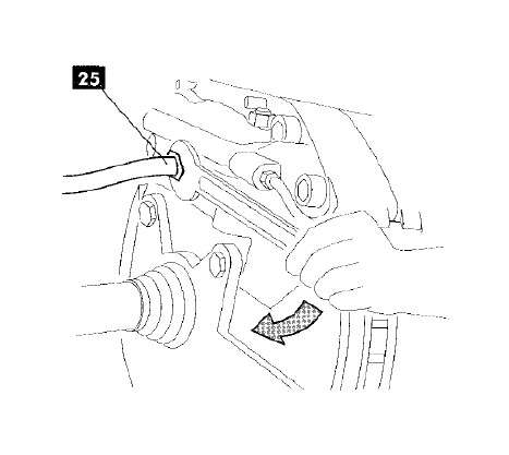
(T)Tighten the caliper end of the brake line (25)or the banjo bolt (20), depending on which your system is equipped with.
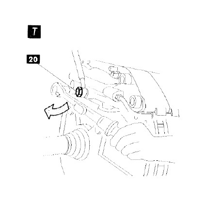
Torque to 20 Nm (15 Ft lbs) ensuring that the line does not become twisted
Temporarily install the wheel and move the steering through its full range of motion; and inspect the brake line installation to ensure that it does not kink, stretch, or unnecessarily come in contact with suspension chassis components. The brake line may be "indexed" in order to achieve the best fitment under all conditions.
Repeat these operations for the other side of the vehicle.
Bleeding the Brake System
Caution:
> Air trapped in the brake circuit severely hampers its function. The bleeding procedure must be carefully performed.
> Use caution to ensure that brake fluid does not come in contact with any painted surfaces. If brake fluid should contact these surfaces, wash them immediately, or damage could result.
> Use brake fluid type specified by vehicle manufacturer to avoid possible fluid incompatibilities. Only use new fluid directly out of the bottle.
> There are several acceptable methods of brake bleeding. Detailed below is merely one option.
> There are either 1 or 2 bleed screws on each caliper. The bleeding procedure must be performed on all bleed screws that are in the system.
> During the bleeding procedure, ensure that the brake fluid reservoir on the master cylinder does not fall below the minimum level marked on the reservoir.
Brembo instructions from the red install book.
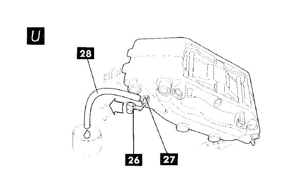
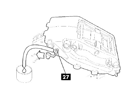
(U)Remove protective cap(26)from the inboard bleed screw (27)
(U)Slide the supplied bleeder hose (28) over the bleed screw (27)
(U)Place the free end of the hose into a collection tank to collect the expelled fluid
Repeatedly press the brake pedal
(V)Keep the brake pedal pressed either by obtaining the assistance of another person, or by placing a spacer(4)between the brake pedal and the seat
(W)Loosen the bleed screw (27)½ to ¾ of a turn, allowing fluid and air to escape
(W)While the pedal is still depressed, tighten the bleed screw so that it is seated, but do not over tighten
• Allow the brake pedal to return to the relaxed position, wait several seconds, and repeat the preceding operations until clean fluid, free of air bubbles emerges.
• Repeat these operations for the outboard bleed screw
• Repeat entire procedure for opposite side of vehicle
Notes
Despite the proper execution of the bleeding procedure, there may be small air bubbles trapped in the small gap between the pistons and the piston bores in the calipers. The following steps describe the best method of ensuring that this air is removed. If a piston retractor such as that used in the following steps is unavailable, it is possible to use a pair of pliers with protected jaws to perform the same function. Use caution to ensure that no damage is caused to the caliper or pads if performing the procedure in this manner.
(X)Remove protective cap(26)from the inboard bleed screw (27)
(X)Slide the supplied bleeder hose (28) over the bleed screw (27)
(X)Place the free end of the hose (28) into a collection tank to collect the expelled fluid
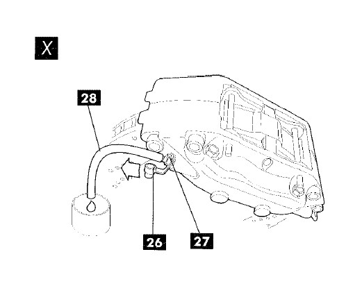
Press the brake pedal several times to ensure the brake pads are in contact with the disc.
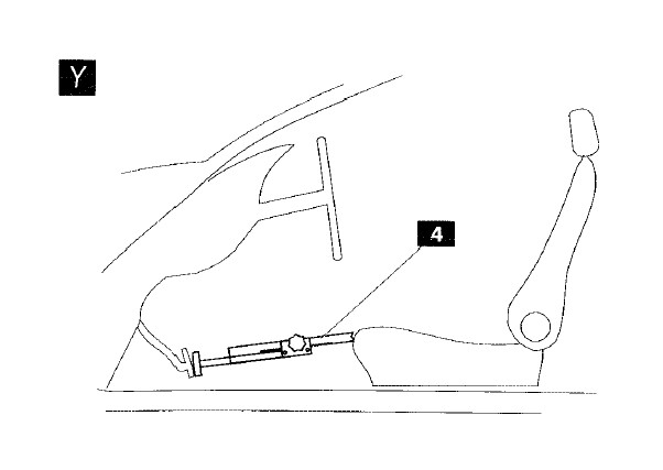
(Y)Keep the brake pedal pressed either by obtaining the assistance of another person, or by placing a spacer(4)between the brake pedal and the seat
(Z)Loosen the bleed screw (27)½ to ¾ of a turn, allowing fluid and air to escape
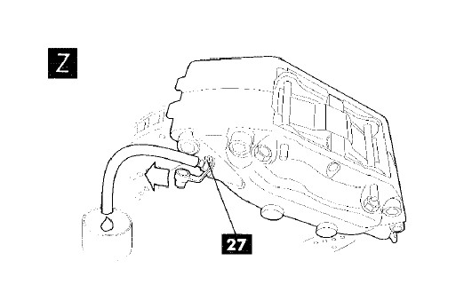
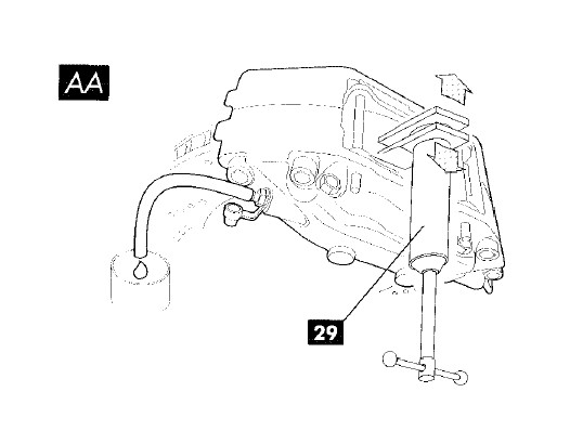
(AA)Use the retractor (29)to push the pistons back into the caliper. This will force fluid and any air which was trapped out through the open bleed screw.
Notes
During the bleeding procedure, ensure that the brake fluid reservoir on the master cylinder does not fall below the minimum level marked on the reservoir.
NOTE: (after install)
After installation or bleeding of the brake system, flush any brake fluid from around the bleed screws, etc, using soapy water. Over time, brake fluid trapped in these areas may cause paint damage. Additionally, do not use acidic wheel cleaners when washing your vehicle, as they can cause damage to the caliper finish and aluminum disc mounting bells, as well as to the wheels themselves. Use only soap and water when cleaning wheels or braking components.
• Press the brake pedal to it's final travel and hold
• Tighten bleed screw
• Allow the brake pedal to return to the relaxed position. Repeatedly press the brake pedal until it becomes firm.
• Repeat process once, beginning from step (U)
• If so equipped, repeat these operations for the outboard bleed screw.
• Repeat entire procedure for opposite side of vehicle.
• Torque all bleed screws to 14 Nm (10 ft lbs)
• Inspect for the any fluid leaks while system is under pressure.
• Check the fluid level in the brake fluid reservoir. Fill to the maximum level indicated on the reservoir.
• Reinstall the wheels and torque the wheel nits to the vehicle manufacturer's specification.
• Carefully lower the vehicle in compliance with safety standards.
Bedding New Pads and Disc
Caution: proceed with caution. Do not use brake system heavily until the following procedure has been completed.
• While the vehicle is stationary, pump brakes to ensure a firm pedal.
• Drive the vehicle cautiously to test fit and function
• Brakes should be smooth, with no vibrations, judder, etc.
• Drive the vehicle to a remote area and perform at least 30 brake applications of 3 second duration.
• Use light / medium deceleration with varying starting speeds. Leave at least 1/2 mile between each brake application.
• The purpose of this procedure is to gradually increase the temperature in the components without thermal shock, and to mate the brake pad and disc friction surfaces.
• After the repeated stops, drive the vehicle for several miles with little or no braking in order to adequately cool the components.
• The system is now ready for normal use.

