FREE 1 to 3-Day Delivery on Orders $149+ Details
How to Install Belltech Street Performance Shock Set for +2 in. to - 2 in. Front / 2 in. to 3 in. Rear Drop (09-13 4WD, Excluding Raptor) on your Ford F-150
Installation Time
3 hours
Tools Required
- Blocks and Wheel chocks
- Ratcheting Socket Wrench
- Safety Glasses
- Floor jack and Jack Stands
- Torque Wrench 10-75 lb ft. range
- Properly rated floor jacks and support stands
- Combination Wrench
- Torque wrench: 0-75 lb ft. range
- Open Wrench

Shop Parts in this Guide
- Belltech Street Performance Front and Rear Shocks for +2 to -2-Inch Front / 2 to 3-Inch Rear Drop (09-13 4WD F-150, Excluding Raptor)
- Belltech Street Performance Front Strut for +2 to -2-Inch Drop (04-13 4WD F-150, Excluding Raptor)
- Belltech Stage 3 Lowering Kit with Street Performance Shocks; +2 to -2-Inch Front / 2-Inch Rear (09-13 4WD F-150, Excluding Raptor)
THIS KIT GIVES YOU THE OPTION OF A 1” TO 2” DROP AS WELL AS A 1” TO 2” LIFT IN ½” INCREMENTS FOR YOUR 4WD 04-UP FORD F150.
Note: Confirm that all of the hardware listed in the parts list is in the kit. DO NOT begin this installation if any part is missing. Read the instructions thoroughly before beginning this installation.
Warning: DO NOT work under a vehicle supported by only a jack. Place support stands securely under the vehicle in the manufacturer’s specified locations unless otherwise instructed.
Warning: DO NOT drive the vehicle until all work has been completed and checked. Torque all hard ware to values specified.
Reminder: Proper use of safety equipment and eye/face/hand protection is absolutely necessary when using these tools to perform procedures!
Note: It is very helpful to have an assistant available during the installation process.
Note: We DO NOT RECOMMEND using wheel ramps while performing this installation.
1 KIT INSTALLATION
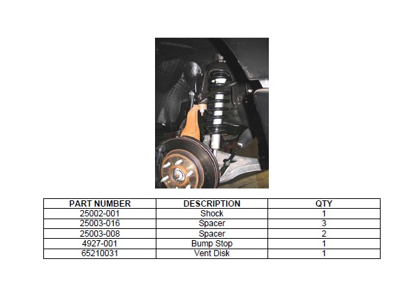
1a. Open the hardware kit and remove all of the contents. Refer to the parts list (Page 6) to verify that all parts are present. Do not begin work if parts are missing.
1b. Park the vehicle on a smooth, level concrete or seasoned asphalt surface and activate the parking brake. Block the REAR wheels of the vehicle with appropriate wheel chocks; making sure the vehicle’s transmission is in 1st gear (manual) or “Park” (automatic).
1c. Using a properly rated floor jack, lift the FRONT wheels of the vehicle off the ground. Place support stands, rated for the vehicle’s weight and in the factory specified locations. Refer to the vehicle Owner’s Manual. Prior to lowering the vehicle onto the stands, make sure the supports will securely contact the chassis.
1d. It is very important that the vehicle is properly supported during this installation to prevent personal injury and chassis damage. Make sure that the support stands are properly placed prior to performing the following procedures. We DO NOT RECOMMEND using wheel ramps while performing this installation.
REMOVING THE O.E.M. FRONT STRUT
2a. Locate the top three mount bolts of the front spring/strut assembly.
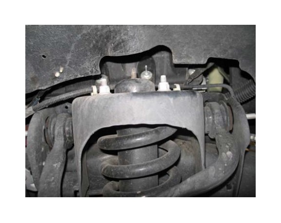
2b. Remove all three mounting nuts that attaches the top of the spring/strut assembly to the chassis.
2c. As you did for the top mounts, remove the bottom mounting bolt of the spring/strut assembly.
3. END LINK &STEERING ARM REMOVAL
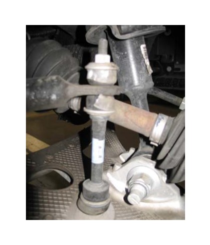
3a. Locate the end link mounts. Un-bolt the mount nuts to the end links. Remove the end links completely.
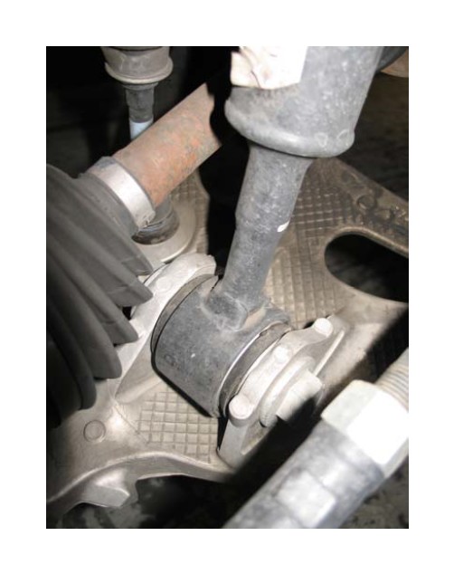
3b. Locate Steering arm link at spindle. Unbolt the steering arm bolt and disconnect stud from spindle.
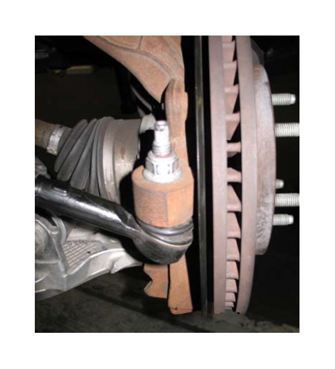
4. REMOVE THE SPRING/STRUT COMPLETELY
4a. Once all mounts have been un-bolted, hold the spindle assembly and slightly pushing down dislodging the bottom spring/strut assembly from its bottom mounts dislodging the entire spring/strut assembly from its perch.
! Coil springs may be under tension. Springs under tension store a great amount of energy. Use caution during the following steps to avoid personal injury and/or damage to vehicle. Be careful not to damage the brake hoses.
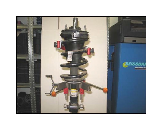
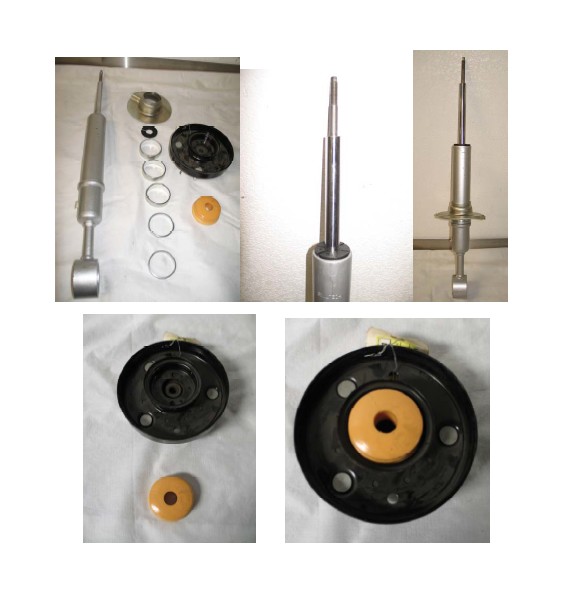
PRE-ASSEMBLY OF THE STRUT
The installation shown has been done at a professional installation shop.
5a. Mount the entire spring/strut assembly in the fixture. To ease the installation of the new strut, mark a white line down the center of the assembly for alignment purposes only showing the front of the top mount
5b. Using an open wrench, remove the top mount.
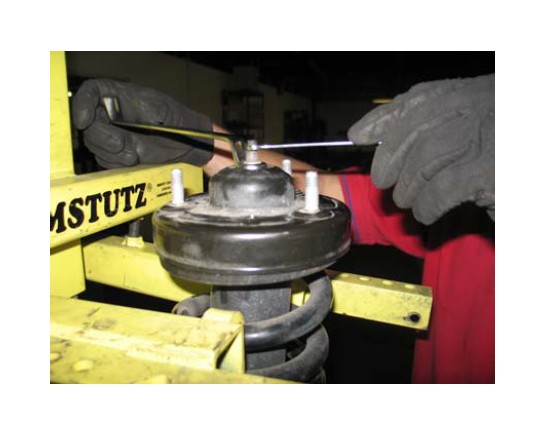
5d. Install your required spacers for the desired height.
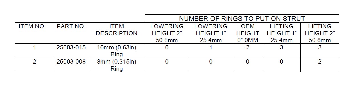
NOTE: If a half inch increment height, between -3 and 1 inches, is desired, please add one 25003-008 ring to the shock from the next lowest increment from the table above. For example, if a 2.5 inch drop is desired, place one 25003-008 ring on the shock (one more ring than on -3 inch drop).
5e. Assemble the new BELLTECH height adjustable strut using the Belltech spring perch, OEM spring, Belltech bump stop and the OEM top mount.
6. RE-ASSEMBLY OF THE FRONT SHOCK/SPRING
6a. Re-install on the new assembly, the shock/spring the same way the O.E.M. shock/spring was removed.
6b. In reverse order, follow Steps 2c thru 2a.
6c. Reattached swaybar end links to 18ft-lbs.
7. FINALIZING THE INSTALLATION
All hardware being fastened to the vehicle’s original fastening points should be torqued to the proper specifications. To prevent chassis damage, never over-torque the hardware.
7a. Check that all components and fasteners have been properly installed, tightened and torqued
7b. Check brake hoses and other components for any possible interference.
7c. Lift the vehicle and remove the support stands. Carefully lower the vehicle to the ground.
7d. Immediately test-drive the vehicle in a remote location so that you can become accustomed to the revised driving characteristics and handling. Be aware that the vehicle will handle substantially different now that it has been modified.
7e. Installation is complete. Check all of the hardware and re-torque at intervals for the first 10, 100, 1000 miles.