FREE 1 to 3-Day Delivery on Orders $149+ Details
How to Install Belltech Stage 1 2 in. or 3 in. Front / 2 in. Rear Lowering Kit (09-13 2WD Regular Cab w/ 6.5 ft. Bed) on your Ford F-150
Installation Time
4 hours
Tools Required
- Properly rated floor jack and six & support stands
- Wheel chocks
- Metric socket set
- Metric box wrench set
- Pneumatic die grinder with carbide metal cutting bit
- Pneumatic ½” drive impact wrench
- Scribe
- Safety Glasses

Shop Parts in this Guide
Congratulations! You were selective enough to choose a BELLTECH PRODUCT. We have spent many hours developing our line of products so that you will receive maximum performance with minimum difficulty during installation.
Warning: Do not work under a vehicle supported by only a jack. Place support stands securely under the vehicle in the manufacturer’s specified locations unless otherwise instructed.
Warning: Do not drive vehicle until all work has been completed and checked. Torque all hardware to values specified.
Reminder: Proper use of safety equipment and eye/face/hand protection is absolutely necessary when using these tools to perform procedures!
Note: It is very helpful to have an assistant available during installation.
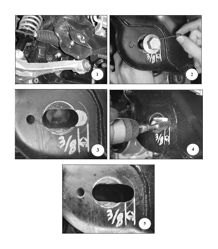
IMPORTANT NOTE: ! This process is not normally needed for the Belltech 2” coils but is recommended for use with the Belltech 3” drop coil springs allowing for additional adjustment to obtain proper alignment.
LENGTHENING THE ALIGNMENT SLOT
1. Remove the bolts from the lower control arm using a 21mm & 27mm wrench and or socket.
2. Pull the lower control arms down and out of the way to allow for a working area within the slotted holes (photo 1).
3. Insert a stock bolt in the slot locations on the lower control arm mount, position the bolt against inner slot side then scribe a line along the bolt flange (Photo 2). It is helpful to outline the profile so it can be easily fallowed while cutting (Photo 3). Perform this marking technique on all eight slots.
4. Using a die grinder and carbide metal cutting bit remove the material outlined as preformed in step 3 (Photo 4). Photo 5 shows proper material removal.
5. Once all the holes have been slotted remove any burrs then reattach the lower control arms.