 FREE 1 to 3-Day Delivery on Orders $149+ Details
How to Install Barricade Extreme HD Rear Bumper on your Ford F-150

Shop Parts in this Guide
PROCEDURE:
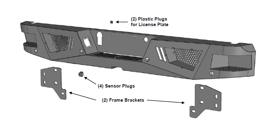
REMOVE CONTENTS FROM BOX. VERIFY ALL PARTS ARE PRESENT. READ INSTRUCTIONS CAREFULLY BEFORE STARTING INSTALLATION. BUMPER IS HEAVY, ASSISTANCE IS RECOMMENDED TO AVOID POSSIBLE INJURY OR DAMAGE TO THE VEHICLE.
IMPORTANT: OEM “HD” RECEIVER HITCH INTEGRATED INTO FACTORY REAR BUMPER CANNOT BE REINSTALLED. INSTALLATION IS COMPATIBLE WITH OEM “MAX DUTY” HITCH AND MOST AFTERMARKET RECEIVER HITCHES.
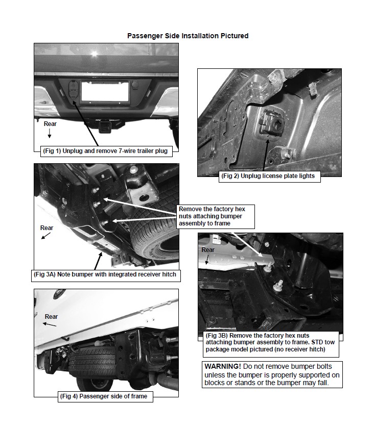
1. Remove the license plate from the bumper, (Figure 1). Next, unplug the license plate lights, trailer plug and sensors, (if equipped). Release the wiring harness from the clips attached to the back of the bumper. Move all wiring harnesses away from bumper. NOTE: Bumper is designed to be compatible with larger 7-wire universal trailer harness plug.
2. Next, release the clips holding the license plate lights in place and remove the lights, (Figure 2). Release the clips securing the trailer plug and remove the plug.
3. Place blocks or jack stands under the bumper to support it during mounting bolt removal. Once the bumper has been safely supported, remove the factory hardware attaching the bumper to the end of the frame and remove the bumper, (Figures 3A, 3B & 4). WARNING! Assistance is required to hold the bumper in place during hardware removal to prevent bumper from falling.
IMPORTANT: On models with FORD “HD” tow package, the factory bumper features an integrated receiver hitch and it cannot be reinstalled with the replacement Bumper, (Figure 3A). Bumper is compatible with models without receiver hitch, (standard tow package-Figure 3B), and with the FORD “MAX DUTY” tow package, (separate receiver hitch). Bumper is also compatible with most replacement receiver hitches.
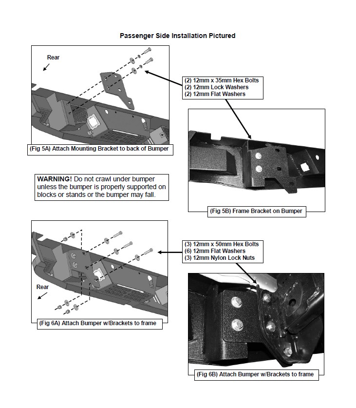
4. Select (1) Mounting Bracket, (Figure 5A). Attach the Bracket to the passenger side mounting plate on the back of the bumper with the included (2) 12mm x 35mm Hex Bolts, (2) 12mm Lock Washers and (2) 12mm Flat Washers, (Figures 5A & 5B). Snug but do not fully tighten at this time. Repeat this Step to attach the Mounting Bracket on the driver side.
5. With assistance, position the Bumper Assembly up to the mounting flanges on the end of the frame. Temporarily support the weight of the Bumper. WARNING: To avoid possible injury or damage to the vehicle, do not proceed until the bumper is fully and safely supported.
6. Attach the Bumper Brackets to the ends of the frame with the included (6) 12mm x 50mm Hex Bolts, (12) 12mm Flat Washers and (6) 12mm Nylon Lock Nuts, (Figures 6A & 6B). Do not tighten hardware.
7. Level and adjust the bumper and fully tighten all hardware including the Mounting Bracket to Bumper hardware.
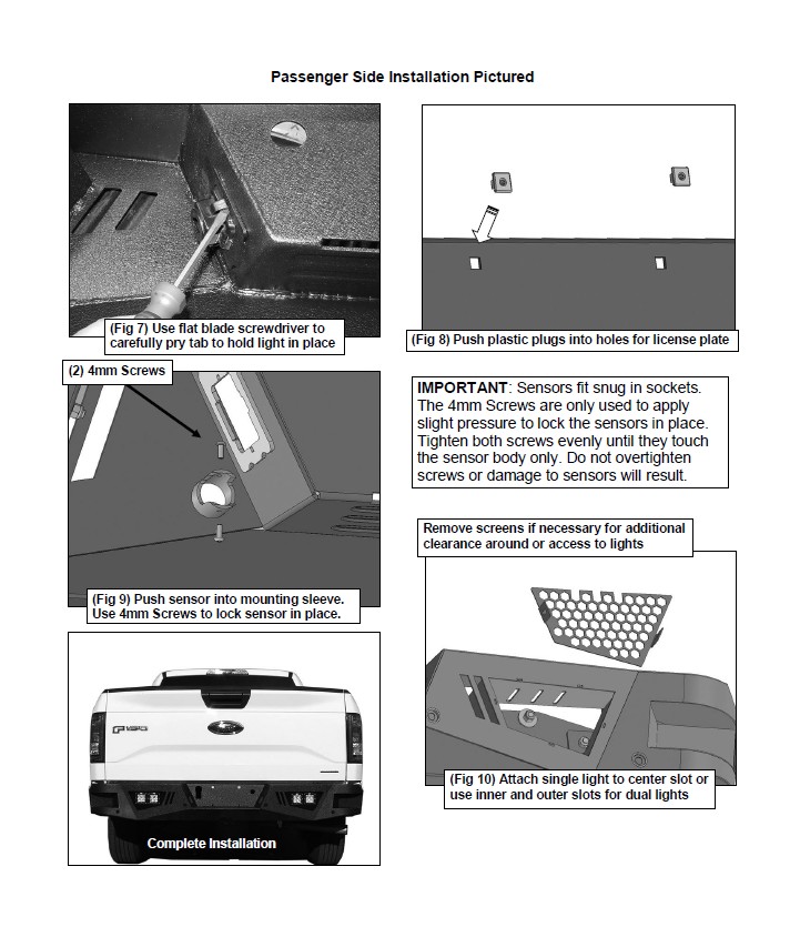
8. Reinstall the license plate lights and trailer plug, (Figure 7). NOTE: Use a flat blade screwdriver to carefully pry the metal clip on the plug out to grab the edge of the opening.
9. Use the included (2) push-in plugs to attach the license plate to the Bumper, (Figure 8).
10. Models with bumper mounted sensors:
a. Remove the rubber plugs from the sockets in the bumper assembly. Push the sensor in from the back of the bumper. Secure each sensor to the socket with (2) 4mm x 10mm Button Head Screws, (Figure 9). IMPORTANT: Sensors fit snug in sockets. The 4mm Screws are used to apply slight pressure to lock the sensors in place. Tighten both screws evenly until they touch the sensor body only. Do not overtighten screws or damage to sensors will result.
b. Reattach the factory wiring harness to sensors.
11. Attach the wiring harness to the lights and trailer plug.
12. Do periodic inspections to the installation to make sure that all hardware is secure and tight.
13. LED light installation at ends of bumper as supplied with bumper or sold separately.
a. Insert light into opening and up to mounting slots. Check for clearance between front and back of light. If necessary, remove the screen from the back of the opening for additional clearance or access to light, (Figure 10).
b. Follow the light manufacturer’s instructions to attach (1) light to the center slot or (2) lights to the inner and outer slots in the top of the light opening.
c. Repeat the above steps for passenger side light installation.
d. Follow light manufacturer’s instructions to properly wire the light.
14. Use the included Wire Ties to secure the wiring harness to the bumper and frame as necessary.
15. Do periodic inspections to the installation to make sure that all hardware is secure and tight.
To protect your investment, wax this product after installing. Regular waxing is recommended to add a protective layer over the finish. Do not use any type of polish or wax that may contain abrasives that could damage the finish. Mild soap may be used to clean the Bumper assembly.
PROCEDURE:
1. REMOVE CONTENTS FROM BOX. VERIFY ALL PARTS ARE PRESENT. READ INSTRUCTIONS CAREFULLY. DRILLING IS REQUIRED. ELECTRICAL KNOWLEDGE IS HIGHLY RECOMMENDED.
2. Install Light into product as instructed. Open hood and disconnect battery.
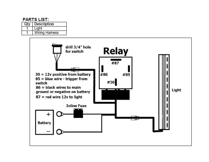
3. Unwrap preassembled wiring harness. Disconnect the plug in the harness leading to the lighted switch. Locate suitable mounting location for switch. Drill 3/4” hole in panel to mount switch. IMPORTANT: Do not drill any holes in panel until back of location is properly checked for clearance. Use of safety goggles is required.
4. Run switch harness through firewall on vehicle. Drill hole through firewall as required for harness plug. Highly recommend use of rubber grommet (not included) to protect harness. Feed switch harness plug through hole in firewall. Seal firewall with silicone as necessary.
5. Attach Relay and main harness to suitable location near battery (firewall or inner fender for example). Do not connect to battery at this time.
6. Attach switch plug to switch harness and tie harness away from anything that could damage harness.
7. Run the prewired light harness down to the light. Plug harness into prewired plug on light. Tie wiring harness away from anything that could damage harness.
8. Attach the fused red positive and black negative wires on the main harness to the battery. NOTE: Attach black negative wire to negative terminal on battery or suitable chassis ground.
9. Reattach battery cables to battery. Installation is complete.
10. Do periodic inspections to the installation to make sure that all hardware is secure and tight and all wiring harnesses are properly secured and free from excessive movement.
