FREE 1 to 3-Day Delivery on Orders $149+ Details
How to Install Husky Custom Molded Rear Mud Guards on your Ram
Installation Time
30 minutes
Tools Required
- Short Phillips screwdriver
- Center punch
- Drill / 1/8” drill bit

Shop Parts in this Guide
Package Contents
• Driver & passenger side rear mud guard
• #10 SEM Screws (qty. 4)
• Small U-Clips (qty. 2)
• Paint Protection Film (1 set)
• Instruction sheet
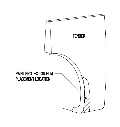
PAINT PROTECTION FILM - INSTALLATION
NOTE: The Paint Protection Film is a precut template of film used to protect the mud guard mounting surfaces of your fenders against wear. The templates (left and right side) can be removed from the backing liner by folding the liner at the center cut of the template, separating the film sides and peeling the film templates from the backing liner.
1. Position mud guard on fender to indicate placement location of paint protection film.
2. Clean the placement area of fender with a clean cotton cloth and a petroleum distillate based cleaner such as DuPont Prep-Sol Brand Solvent Cleaner or 3M Brand Adhesive Cleaner and dry.
3. Mix a wetting solution of 1 pint of water with 4 drops of liquid dishwashing detergent.
4. Mark correct position of film by placing mud guard against fender.
5. Remove protection film from liner and flood adhesive side of film with wetting solution (use a spray bottle or sponge).
6. Thoroughly wet film placement location of fender with wetting solution.
7. Position the adhesive side of film on fender and flood with wetting solution.
8. Check location of film with mud guard and reposition as necessary.
9. Using a sponge, squeegee any air bubbles and wrinkles from film.
10. Allow film to dry before installing mud guard.
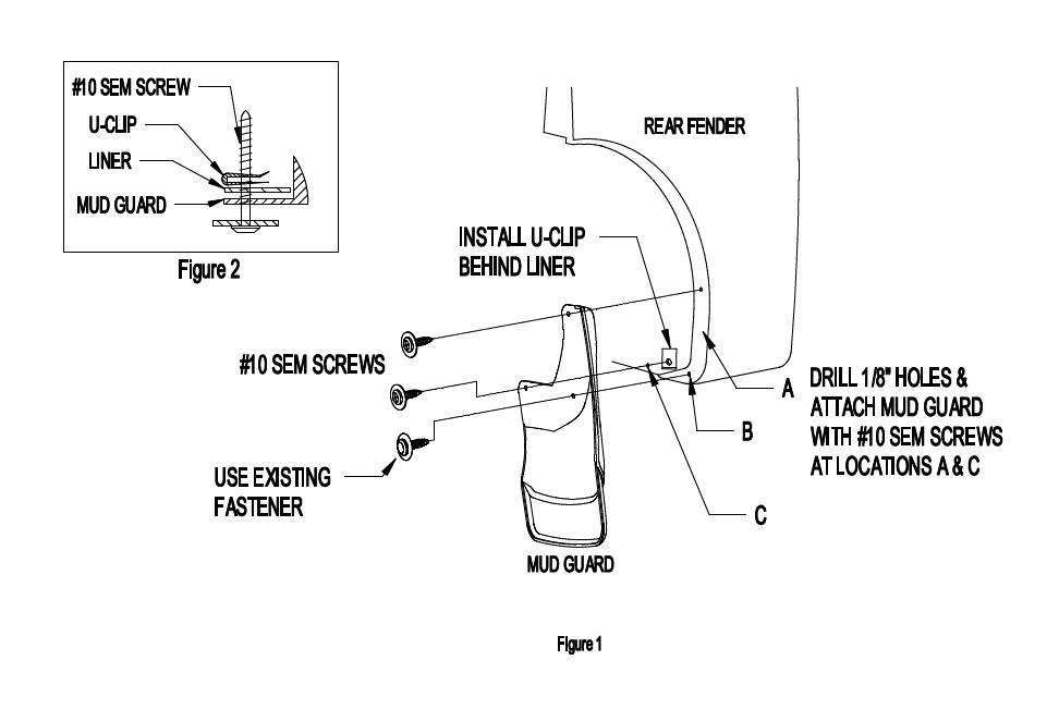
MUD GUARD INSTALLATION
NOTE: It may be necessary to turn the wheels all the way left or right depending on the tools being used for installation.
1. Remove the existing fastener from location B (Figure 1).
2. Attach the Mud Guard at location B with the existing fastener, check the Mud Guard fit and appearance before tightening.
3. Using the mud guard as a template, mark and drill 1/8” holes at locations A and C.
4. Install a #10 SEM Screw at location A (Figure 1).
5. Install a #10 SEM Screw thru the mud guard and into the U-Clip placed on the backside of the fender liner at location C. NOTE: DO NOT clip the u-clip over the fender liner (Figure 2).
PAINTING INSTRUCTIONS
1. Clean mud guard with a soap and water to remove dirt and other contaminates.
2. Sand painting surface with 320 grit sand paper.
3. Apply a coating of flexible primer-adhesion promoter.
4. Apply a flexible paint as directed by the paint manufacturer.