FREE 1 to 3-Day Delivery on Orders $149+ Details
How to Install Air Lift Load Lifter 5000 (04-14 4WD) on your Ford F-150
Tools Required
- Hoist or Floor Jacks
- Safety Stands
- Safety Glasses
- Torque Wrench
- Standard Open-end Combo Wrenches
- Ratchet
- Metric and Standard Sockets
- #6 Metric Allen Wrench (socket if available)
- 7/32 Allen Wrench (socket if available)
- Flat Head Screw Driver
- Hack Saw or Grinder
- 5/16 Drill Bit (very sharp)
- Heavy Duty Drill
- Hose Cutter, Razor Blade or Sharp Knife
- Air Compressor or Compressed Air Source
- Spray Bottle with Dish Soap/Water Solution

Shop Parts in this Guide
Installation Diagram

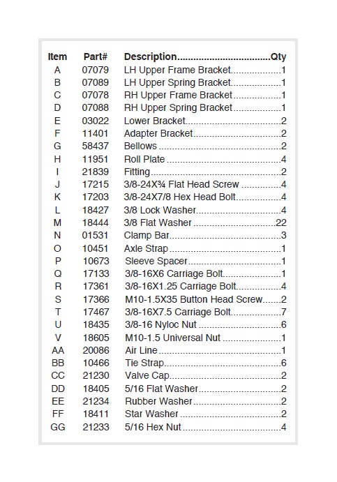
HARDWARE LIST
Installing the LoadLifter 5000 Ultimate System
GETTING STARTED
COMPRESSED AIR CAN CAUSE INJURY AND DAMAGE TO THE VEHICLE AND PARTS IF IT IS NOT HANDLED PROPERLY. FOR YOUR SAFETY, DO NOT TRY TO INFLATE THE AIR SPRINGS UNTIL THEY HAVE BEEN PROPERLY SECURED TO THE VEHICLE.
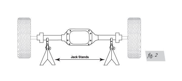
1. Raise the vehicle and support the axle with jack stands, setting the jack stands as wide as possible on the axle (fig. 2).
2. Drop the axle or raise the frame up to make room for the assemblies to be put into position between the frame and axle.
3. Remove both jounce bumpers between the frame and axle (figs. 3a or 3b) and for early 04-08 models remove the stock Universal Nut that held the jounce bumpers in place (fig. 4).
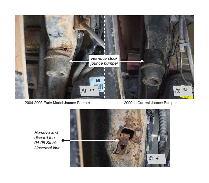
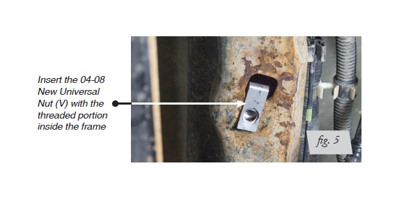
4. For the early 04-08 models, install a new Universal Nut (V) into the large hole so that the threaded portion is up inside the frame (fig. 5).
NOTE: No modifications are needed for the 2009 to current models.
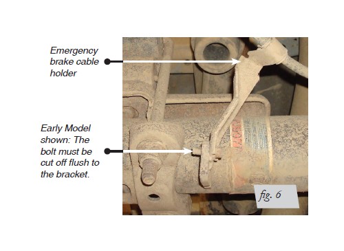
5. All years: On the right side (passenger side) there is an emergency brake cable holder that is bolted on to a bracket welded to the axle, with a self-taping bolt. In order to make clearance for the axle strap, it will be necessary to cut this off and/or grind this bolt flush to the bracket (fig. 6).
BELLOWS AND BRACKET ASSEMBLY
1. Set a roll plate (H) over the top of the bellows (G) (fig. 1).
NOTE: The radiused (rounded) edge of the roll plate (G) will be towards the bellows so that the bellows is seated inside both roll plates.
2. Install the straight fitting (I) into the top of the bellows finger tight. Tighten the fitting one and a half turns.
3. Install the upper spring bracket (B & D) onto the bellows (G) using four (J) flat head screws (fig. 1). Torque the upper spring bracket to no more than 20ft. lbs.
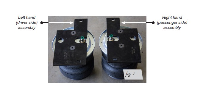
4. These are right and left hand specific. The left assembly goes on the driver side; the right assembly goes on the passenger side (fig. 7). Set aside for later use.
ATTACHING THE ASSEMBLIES TO THE FRAME
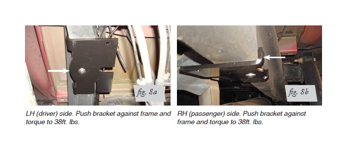
1. With the new universal nut in the frame on the early model and no modification needed for the late model truck, attach the left frame mount bracket (A) onto the frame using a flat washer (M) and button head screw (S). Mount on the frame with the flange pointing up and as tight to the frame as you can get it while tightening the hardware (figs. 8a & 8b). Torque to 38ft. lbs. Repeat for the right side frame mount bracket (C).
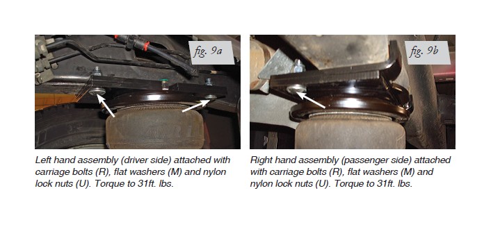
2. Attach the left and right hand assemblies to the frame brackets using carriage bolts (R), flat washers (M) and nylon lock nuts (U) (figs. 9a & 9b). Torque to 31ft. lbs.
LOWER BRACKET INSTALLATION (2004-2008 MODELS)
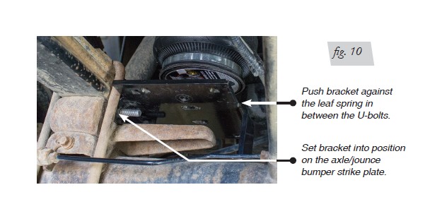
1. Set one of the lower brackets on the axle and axle spacer/jounce bumper strike plate.
NOTE: The bracket must nest in between the stock U-bolts that hold the leaf spring to the axle (fig. 10). Repeat for the other side.
2. Left side (driver) installation: insert the long carriage bolts (T) into the bottom bracket.
NOTE: The inside square holes must be used for the carriage bolts (fig. 11).
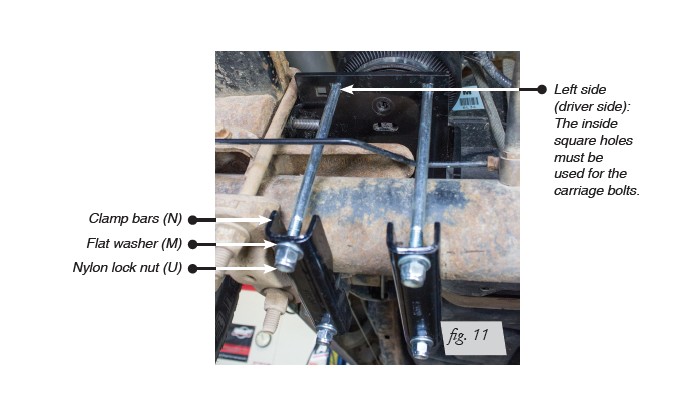
3. Install the lower clamp bars (N) over the carriage bolts installed previously and cap with flat washers (M) and nylon lock nuts (U) (fig. 11). Torque the lower nuts evenly to 10ft. lbs.
NOTE: Make sure the lower bracket stays against the leaf spring and in between the stock U-bolts (fig. 10).
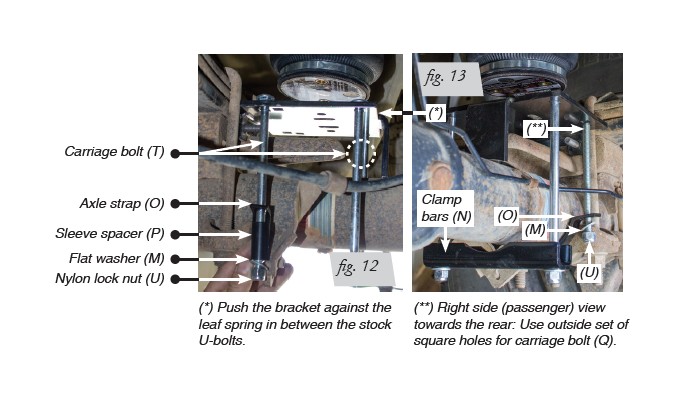
4. Right side (passenger) installation: insert two long carriage bolts (T) into the square holes on the furthest inside set of holes (fig. 12). Set the axle strap (O) under the axle in between the emergency brake cable bracket and leaf spring retainer.
NOTE: The flange must be above the stock spring retainer, forward of the axle.
Insert the last long carriage bolt (T) on the outside square holes, into the axle strap previously set into position. Cap with sleeve spacer (P), flat washer (M) and nylon lock nut (U).
5. On the backside of the axle, cap the axle strap previously installed with a flat washer (M) and nylon lock nut (U) (fig. 13). Install the last lower clamp bar (N) over the two remaining carriage bolts and cap with flat washers (M) and nylon lock nuts (U). Torque the lower nuts evenly to 10ft. lbs.
NOTE: It may be necessary to pry the carriage bolt over slightly with a screwdriver to gain access to the nylon nuts on the axle strap carriage bolts. Make sure the lower bracket stays against the leaf spring and in between the stock U-bolts during the tightening sequence.
LOWER BRACKET INSTALLATION (2009 & UP MODELS)
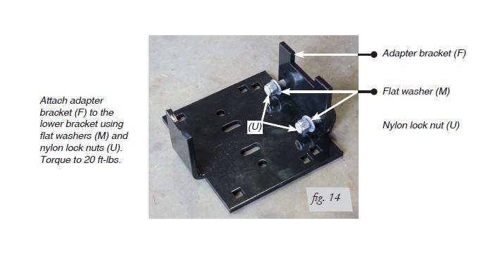
1. For the late model vehicles, there is no jounce bumper strike plate for the lower bracket to sit on. Therefore an adapter bracket has to be used to extend the lower bracket far enough to sit on the axle. Set the adapter bracket (F) over the existing studs in the lower bracket and cap with flat washers (M) and nylon nuts (U) (fig. 14). Torque to 20 ft-lbs.
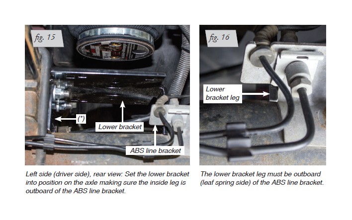
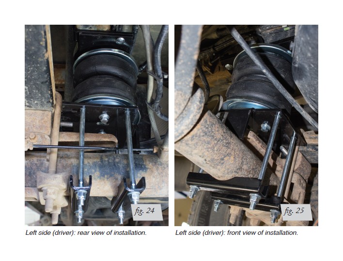
2. Left side (driver): set one of the lower brackets on the axle making sure the inside leg is outboard (leaf spring side) of the ABS line bracket on the axle (figs. 15 & 16). It may be necessary to angle the lower bracket into position. Make sure the lower bracket is pushed against the leaf spring and in between the stock U-bolts.
(*) Push the bracket against the leaf spring in between the stock U-bolts.
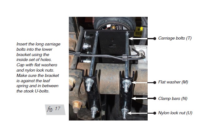
3. Insert the long carriage bolts (T) into the bottom bracket.
NOTE: The inside square holes must be used for the carriage bolts (fig. 17). Install the lower clamp bars (N) over the carriage bolts installed previously and cap with flat washers (M) and nylon lock nuts (U). Torque the lower nuts evenly to 10ft. lbs.
NOTE: Make sure the lower bracket stays against the leaf spring and in between the stock U-bolts.
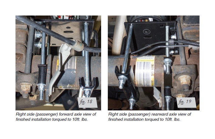
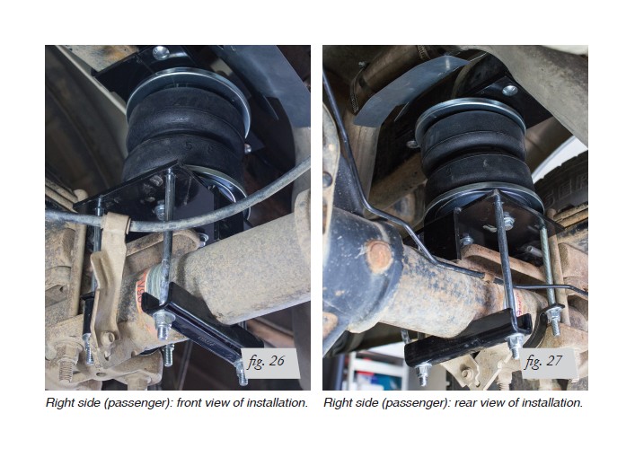
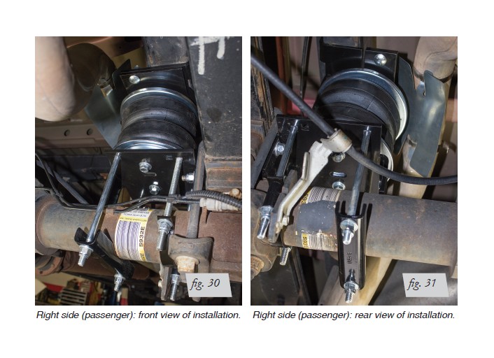
4. Right side (passenger): set the other lower bracket onto the axle making sure the bracket is pushed against the leaf spring and is in between the stock U-bolts. Attach the lower bracket as stated in the figure 12 and 13 instructions noted previously. Torque hardware evenly to 10ft. lbs. (figs. 18 & 19).
LOWER BRACKET TO BELLOWS INSTALLATION
All model years will attach in the same way. The late model is being used for the illustrations.
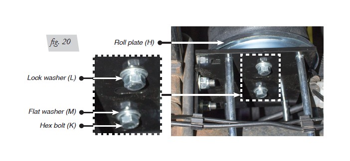
1. Set a roll plate on top of the lower bracket making sure it is positioned correctly to nest over the bottom of the bellows. Try to align the holes in the roll plate with the holes of the lower bracket as close as you can, then raise the axle up so that the roll plate just touches the bellows.
2. Looking below, line up the hole in the roll plate with the bellows and attach using the 3/8 Hex Head bolt (K) lock washer (L) and flat washer (M) (fig. 20). Repeat for the other mounting hole in the bracket. Since it will be hard to torque this bolt, unless using a crows foot wrench adapter, just tighten the hardware securely (no more than 20ft. lbs.). Repeat for the other side.
FINISHING THE INSTALLATION
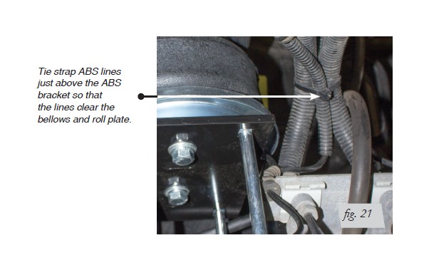
1. For the late model installations the ABS line has to be tied together using a tie strap above the bracket so that is does not rub against the bellows (fig. 21).
2. Drop the axle or raise the frame and remove the jack stands.
INSTALLING THE HEAT SHIELD
Exhaust Clearance Modification
1. Check the exhaust clearance and ensure that it is 2-3 inches from the air cylinder.
2. If necessary, loosen the clamps and move or rotate the cylinder to obtain additional clearance.
Positioning the Heat Shield
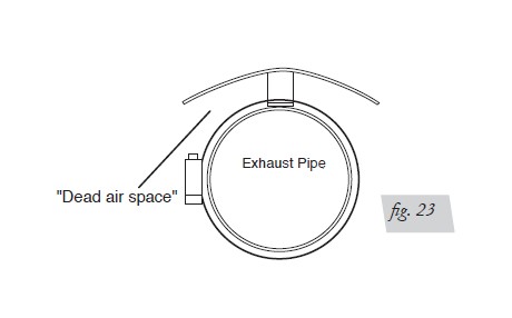
NOTE: The heat shield is installed on the exhaust pipe at the closest point to the air spring to protect the unit from the radiant heat of the exhaust system.
3. Attach radiator clamps loosely around the exhaust pipe nearest to the spring.
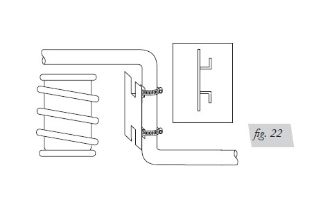
4. Bend the heat shield tab out at a 90˚ angle and again half the distance up at a 90˚ angle to form an “L” shape. Repeat on the other tab (Fig. 22). Position heat shield and insert the heat shield tabs beneath the two radiator clamps. Tighten the clamps (Fig. 22).
5. Bend the heat shield to form it around the tail pipe. Be sure to maintain a “dead air” space of 1/2” to 1” between the tail pipe and the heat shield (Fig. 23).
NOTE: Make sure the installation does not interfere with moving parts, gas lines, etc.
FINISHED INSTALLATION (FOR 2004-2008 MODELS)
FINISHED INSTALLATION (FOR 2009 & UP MODELS)
INSTALLING THE AIR LINES
1. Choose a convenient location for mounting the inflation valves. Popular locations for the inflation valve are:
a. The wheel well flanges
b. The license plate recess in bumper
c. Under the gas cap access door
d. Through the license plate
NOTE: Whatever the chosen location, make sure there is enough clearance around the inflation valves for an air chuck.
2. Drill two 5/16” holes to install the inflation valves.
3. Cut the air line assembly in two equal lengths.
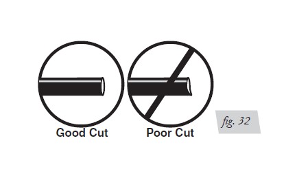
WHEN CUTTING OR TRIMMING THE AIR LINE, USE A HOSE CUTTER, A RAZOR BLADE, OR A SHARP KNIFE. A CLEAN, SQUARE CUT WILL ENSURE AGAINST LEAKS. DO NOT USE WIRE CUTTERS OR SCISSORS TO CUT THE AIR LINE. THESE TOOLS MAY FLATTEN OR CRIMP THE AIR LINE CAUSING IT TO LEAK AROUND THE O-RING SEAL INSIDE THE ELBOW FITTING (FIG. 32).
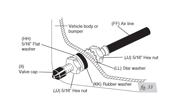
4. Place a 5/16” nut and star washer on the air valve. Leave enough of the inflation valve in front of the nut to extend through the hole and have room for the rubber washer, flat washer, and 5/16” nut and cap. There should be enough valve exposed after installation— approximately 1/2”— to easily apply a pressure gauge or an air chuck (fig. 33).
5. Push the inflation valve through the hole and use the rubber washer, flat washer, and another 5/16” nut to secure it in place. Tighten the nuts to secure the assembly.
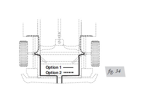
6. Route the air line along the frame to the air fitting on the air spring (fig. 34). Keep AT LEAST 6” of clearance between the air line and heat sources, such as the exhaust pipes, muffler, or catalytic converter. Avoid sharp bends and edges. Use the plastic tie straps to secure the air line to fixed, non-moving points along the chassis. Be sure that the tie straps are tight, but do not pinch the air line. Leave at least 2” of slack to allow for any movement that might pull on the air line.
7. Cut off the air line, leaving approximately 12” of extra air line. A clean square cut will ensure against leaks. Insert the air line into the air fitting. This is a push-to-connect fitting. Simply push the air line into the 90° swivel fitting until it bottoms out (9/16” of air line should be in the fitting).
CHECKING FOR LEAKS
1. Inflate the air spring to 30 PSI.
2. Spray all connections and the inflation valves with a solution of 1/5 liquid dish soap and 4/5 water. Spot leaks easily by looking for bubbles in the soapy water.
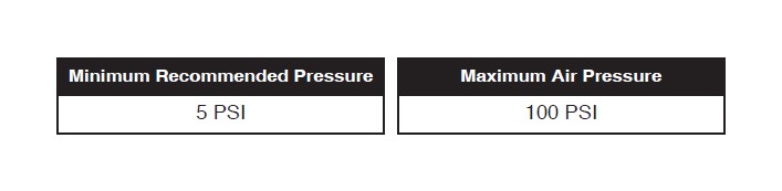
3. After the test, deflate the springs to the minimum pressure required to restore the system to normal ride height. Do not deflate to lower than 5 PSI.
4. Check the air pressure again after 24 hours. A 2-4 PSI loss after initial installation is normal. Retest for leaks if the loss is more than 5 lbs.
FIXING LEAKS
1. If there is a problem with the swivel fitting:
a. Check the air line connection by deflating the spring and removing the line by pulling the collar against the fitting and pulling firmly on the air line. Trim 1” off the end of the air line. Be sure the cut is clean and square (see fig. 12). Reinsert the air line into the push-to-connect fitting.
b. Check the threaded connection by tightening the swivel fitting another ½ turn. If it still leaks, deflate the air spring, remove the fitting, and re-coat the threads with thread sealant. Reinstall by hand tightening as much as possible and then use a wrench for an additional two turns.
2. If there is a problem with the inflation valve:
a. Check the valve core by tightening it with a valve core tool.
b. Check the air line by removing the air line from the barbed type fitting. Cut the air line off a few inches in front of the fitting and use a pair of pliers or vice grips to pull/ twist the air line off of the fitting.
DO NOT CUT OFF THE AIR LINE COMPLETELY AS THIS WILL USUALLY NICK THE BARB AND RENDER THE FITTING USELESS.
3. If the preceding steps have not resolved the problem, call Air Lift customer service at (800) 248-0892.
Before Operating
INSTALLATION CHECKLIST (To be completed by installer)
> Clearance test — Inflate the air springs to 60 PSI and ensure there is at least 1/2” clearance around each bellow, away from anything that might rub against them. Be sure to check the tire, brake drum, frame, shock absorbers and brake cables.
> Leak test before road test — Inflate the air springs to 60 PSI, check all connections for leaks with a soapy water solution. See the Checking for Leaks section for tips on how to spot leaks. All leaks must be eliminated before the vehicle is road tested.
> Heat test — Be sure there is sufficient clearance from any heat sources — at least 6” for air springs and air lines. If a heat shield was included in the kit, install it. If there is no heat shield, but one is required, call (800) 248-0892.
> Fastener test — Recheck all bolts for proper torque. Retorque after 100 miles.
> Road test — The vehicle should be road tested after the preceding tests. Inflate the air springs to 25 PSI (50 PSI if the vehicle is loaded). Drive the vehicle 10 miles and recheck for clearance, loose fasteners and air leaks.
> Operating instructions — If professionally installed, the installer should review the Product Use, Maintenance and Servicing section with the owner. Be sure to provide the owner with all of the paperwork which came with the kit.
POST-INSTALLATION CHECKLIST
> Overnight leak down test — Recheck air pressure after the vehicle has been used for
24 hours. If the pressure has dropped more than 5 PSI, then there is a leak that must
be fixed. Either fix the leak yourself or return to the installer for service.
> Air pressure requirements — Regardless of load, the air pressure should always be
adjusted to maintain ride height at all times.
> Thirty day or 500 mile test —Recheck the air spring system after 30 days or 500 miles, whichever comes first. If any part shows signs of rubbing or abrasion, the source should be identified and moved, if possible. If it is not possible to relocate the cause of the abrasion, the air spring may need to be remounted. If professionally installed, the installer should be consulted. Check all fasteners for tightness.
Product Use, Maintenance and Servicing
MAINTENANCE GUIDELINES
NOTE: By following the steps below, vehicle owners will obtain the longest life and best results from their air springs.
1. Check the air pressure weekly.
2. Always maintain normal ride height. Never inflate beyond 100 PSI.
3. If you develop an air leak in the system, use a soapy water solution (1/5 liquid dish soap and 4/5 water) to check all air line connections and the inflation valve core before deflating and removing the air spring.
FOR YOUR SAFETY AND TO PREVENT POSSIBLE DAMAGE TO YOUR VEHICLE, DO NOT EXCEED MAXIMUM GROSS VEHICLE WEIGHT RATING (GVWR), AS INDICATED BY THE VEHICLE MANUFACTURER. ALTHOUGH YOUR AIR SPRINGS ARE RATED AT A MAXIMUM INFLATION PRESSURE OF 100 PSI, THE AIR PRESSURE ACTUALLY NEEDED IS DEPENDANT ON YOUR LOAD AND GVWR.
4. Loaded vehicles require at least 25 PSI or more. A “loaded vehicle” refers to a vehicle with a heavy bed load, a trailer, or both. As discussed above, never exceed GVWR, regardless of air spring, air pressure, or other load assist. The springs in this kit will support approximately 40 lbs. of load (combined on both springs) for each 1 PSI of pressure. The required air pressure will vary depending on the state of the original suspension. Operating the vehicle below the minimum air spring pressure will void the Air Lift warranty.
5. When increasing load, always adjust the air pressure to maintain the normal ride height. Increase or decrease pressure from the system as necessary to attain normal ride height for optimal ride and handling. Remember that loads carried behind the axle (including tongue loads) require more leveling force (pressure) than those carried directly over the axle.
6. Always add air to springs in small quantities, checking the pressure frequently.
7. Should it become necessary to raise the vehicle by the frame, make sure the system is at minimum pressure (5 PSI) to reduce the tension on the suspension/brake components. Use of on board leveling systems do not require deflation or disconnection.
8. Periodically check the air spring system fasteners for tightness. Also, check the air springs for any signs of rubbing. Realign if necessary.
9. On occasion, give the air springs a hard spray with a garden hose in order to remove mud, sand, gravel or other abrasive debris.
TROUBLESHOOTING GUIDE
1. Leak test the air line connections, the threaded connection into the air spring, and all fittings in the control system.
2. Inspect the air lines to be sure none are pinched. Tie straps may be too tight. Loosen or replace the strap and replace leaking components.
3. Inspect the air line for holes and cracks. Replace as needed.
4. Look for a kink or fold in the air line. Reroute as needed.
If the preceding steps do not solve the problem, it is possibly caused by a failed air spring — either a factory defect or an operating problem. Please call Air Lift at (800) 248-0892 for assistance.
FREQUENTLY ASKED QUESTIONS
Q. Will installing air springs increase the weight ratings of a vehicle?
No. Adding air springs will not change the weight ratings (GAWR, GCWR and/or GVWR) of a vehicle. Exceeding the GVWR is dangerous and voids the Air Lift warranty.
Q. Is it necessary to keep air in the air springs at all times and how much pressure will they need?
For LoadLifter 5000 Ultimate, the recommended minimum air pressure is 5 PSI, but it can safely be run at zero air pressure.
Q. Is it necessary to add a compressor system to the air springs?
No. Air pressure can be adjusted with any type of compressor as long as it can produce sufficient pressure to service the springs. Even a bicycle tire pump can be used, but it’s a lot of work.
Q. How long should air springs last?
If the air springs are properly installed and maintained they can last indefinitely.
Q. Will raising the vehicle on a hoist for service work damage the air springs?
No. The vehicle can be lifted on a hoist for short-term service work such as tire rotation or oil changes. However, if the vehicle will be on the hoist for a prolonged period of time, support the axle with jack stands in order to take the tension off of the air springs.
TUNING THE AIR PRESSURE
Pressure determination comes down to three things — level vehicle, ride comfort, and stability.
1. Level vehicle
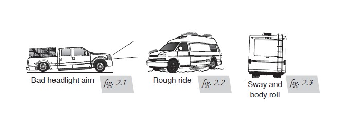
If the vehicle’s headlights are shining into the trees or the vehicle is leaning to one side, then it is not level (fig. 2.1). Raise the air pressure to correct either of these problems and level the vehicle.
2. Ride comfort
If the vehicle has a rough or harsh ride it may be due to either too much pressure or not enough (fig. 2.2). Try different pressures to determine the best ride comfort.
3. Stability
Stability translates into safety and should be the priority, meaning the driver may need to sacrifice a perfectly level and comfortable ride. Stability issues include roll control, bounce, dive during braking and sponginess (fig. 2.3). Tuning out these problems usually requires an increase in pressure.
GUIDELINES FOR ADDING AIR
1. Start with the vehicle level or slightly above.
2. When in doubt, always add air.
3. If the front of the vehicle dives while braking, increase the pressure in the front air bags, if equipped.
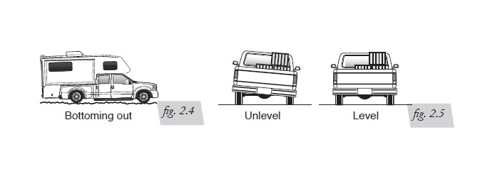
4. If it is ever suspected that the air bags have bottomed out, increase the pressure (fig. 2.4).
5. Adjust the pressure up and down to find the best ride.
6. If the vehicle rocks and rolls, adjust the air pressure to reduce movement.
7. It may be necessary to maintain different pressures on each side of the vehicle. Loads such as water, fuel, and appliances will cause the vehicle to be heavier on one side (fig. 2.5). As much as a 50 PSI difference is not uncommon.
Choosing the Right On-Board Air Compressor System
Add an on-board air compressor sytem to inflate and deflate your air springs with the touch of a button — from inside or outside of the vehicle.
• For convenient, on-the-go control of your air springs, add an Air Lift on-board air compressor system.
• Air Lift on-board air compressor systems eliminate the search for gas stations that have a working compressor, saving you time, energy and money.
• All systems include a compressor, controller and all parts needed for easy installation.
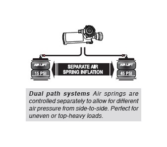
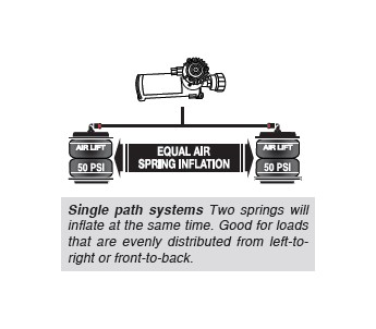
1. Choose single or dual path inflation (see illustrations at right)
2. Choose wireless or analog control
• Wireless: Control your air springs from inside or outside the vehicle. Easiest installation - no wires to the cab.
• Analog: In-cab control of your air springs. Economically priced.
3. Choose heavy or standard duty compressor
• Standard duty: A standard duty compressor will work well for most customers who use their system on an intermittent basis.
• Heavy duty: For daily use, consider the heavy duty compressor - it inflates faster and more quietly than the standard compressor.
Visit www.airliftcompany.com for more detailed info on compressor systems.