 FREE 1 to 3-Day Delivery on Orders $149+ Details
How to Install an Airaid Cold Air Dam Intake - Black - SynthaMax Dry Filter on your Ford F-150
1. Disconnect the negative battery cable.
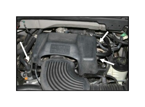
Using a 10mm socket, remove the three bolts that secure the beauty cover over the throttlebody. Remove the cov-er and save these parts for reinstallation in step #16.
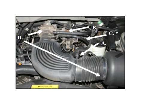
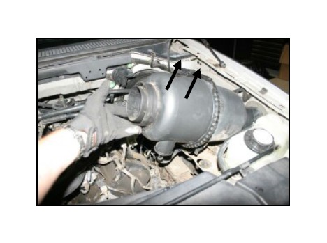
2. A) Very carefully, using a pulling circular motion, remove the air intake temperature sensor from the air intake tube. B) Disconnect the upper hard plastic tube from the air intake tube. C) Disconnect the crankcase breather at the intake tube and the valve cover, and re-move it from the vehicle. D) Loosen two hose clamps and remove the air intake tube from the vehicle.
3. Lift straight up on the outlet side of the air filter canis-ter to remove it from it’s locating grommets. Next, pull it towards the engine to dislodge it from the inner fender well.
4.Unlatch the clamp on the canister to separate the two halves. Once separated, remove the factory air filter.
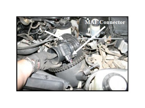
A) Next, slide the large round plastic Mass Air Flow (MAF) sensor adapter plate from the canister. To do this, slide the wires thru the rubber grommet to gain access to the MAF sensor wiring connector. Now dis-connect the MAF sensor wiring harness, and remove the MAF sensor housing and adapter plate. Remove the remaining half of the canister from the vehicle.
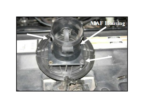
5. Remove the bolts that secure the MAF sensor housing to the adapter. Separate the adapter plate from the MAF sensor housing and save the sensor and housing for rein-stallation in step #7.
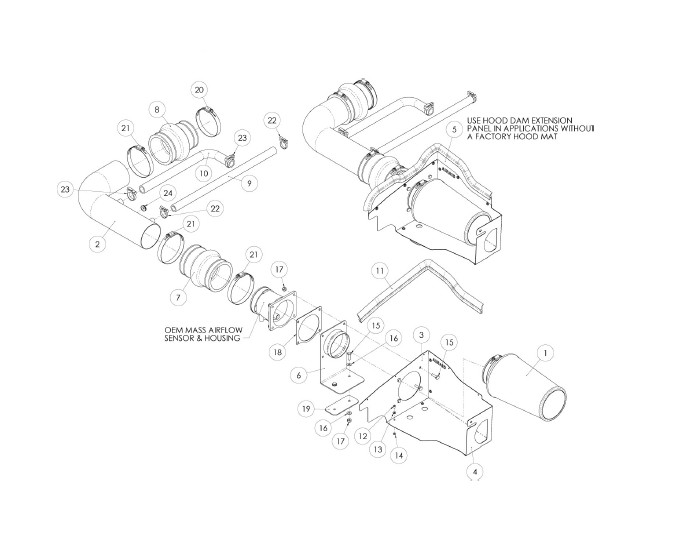
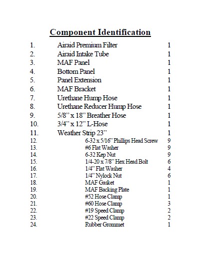
6. Assemble the MAF panel (#3), and bottom panel (#4) as shown using four 6-32 screws (#12), four flat washers (#13), and four Kep nuts (#14) as shown.
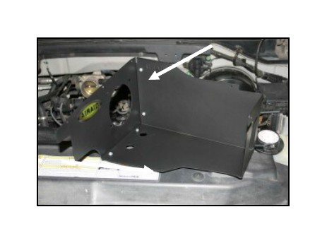
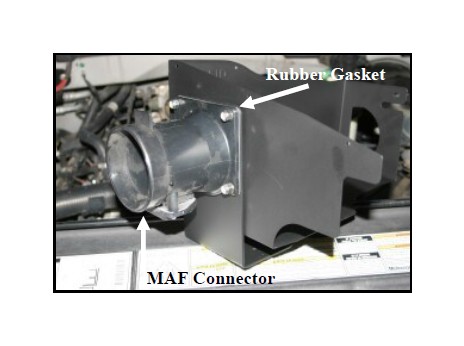
7. Attach the MAF bracket (#6), rubber gasket (#18), and factory MAF sensor housing to the Cold Air Dam (CAD) using four 1/4-20x7/8” hex bolts (#15), and 1/4” Nylock nuts (#17), as shown. Make sure that the MAF sensor connector is on the bottom when assembly is complete. Refer to the line drawing above for reference.
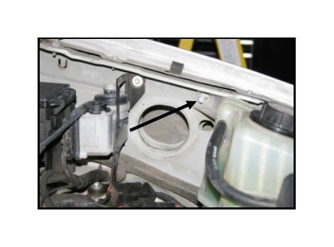
8. Using a 10mm socket, remove and save the bolt that secures the radiator overflow tank to the driver side inner fender well.
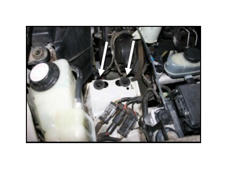
9. Remove the two grommets that held the air filter can-ister in place. They will not be reused.
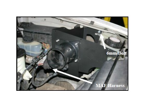
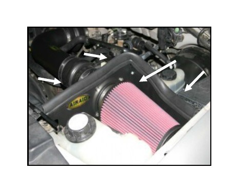
10. Install the CAD assembly into the vehicle using two 1/4-20x7/8” bolts (#15), four 1/4” flat washers (#16), one MAF backing plate (#19), and two 1/4” nylock nuts (#17). Leave the two bolts slightly loose for now for final adjustment. Refer to the line drawing on page 1 for reference. Next, reinstall the 6mm bolt thru the CAD, radiator overflow tank, and into the fender well. Recon-nect the MAF sensor wiring harness.
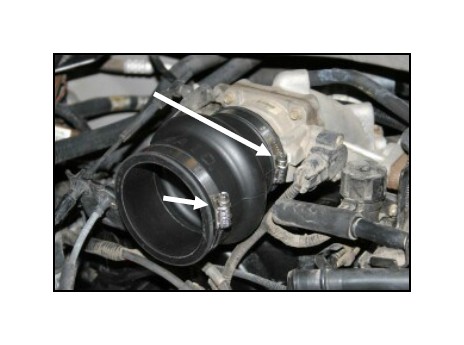
11. Install the hump hose (#7) onto the MAF sensor housing as shown using two #60 hose clamps (#21). Tighten only the clamp on the MAF sensor housing at this time.
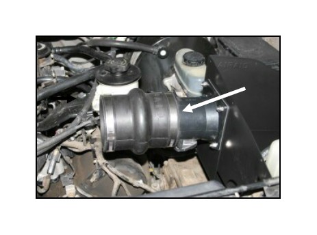
12. Install the small end of the reducing hump hose (#8)onto the throttlebody and tighten the #52 hose clamp (#20). Next, install the remaining #60 hose clamp (#21) on the large end of the hump hose leaving it loose for now.
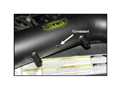
13. Install the supplied rubber grommet (#24) into the Airaid Intake Tube (#2) as shown.
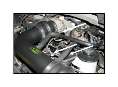
14. Install the Airaid Intake Tube into the hump hose on the MAF, and then into the hump hose on the throttle-body. Adjust for fit, and then tighten the hose clamps. Connect the 5/8”x18” breather hose (#9) between the valve cover and the intake tube as shown using two #19 speed clamps (#22). Now carefully reinstall the intake air temperature sensor into the grommet from step #13. Now that everything is in place, tighten the three bolts that secure the CAD to the vehicle. 5.4L engines: Meas-ure, and then cut the 3/4”x12” L-hose (#10) and then install it between the hard plastic hose and the intake tube as shown using two #22 speed clamps (#23).
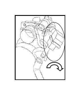
15. 4.6L engines: Rotate the resonator box 90 degrees to provide clearance for the 3/4 x 12” L-hose (#7). Install the 3/4”x12” L-hose (#10) onto the Airaid Intake tube and the resonator box and secure it using the two #22 speed clamps (#23).
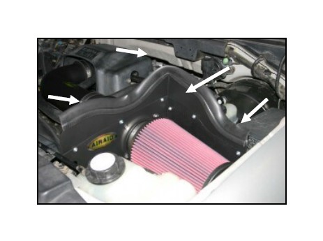
16. Reinstall the beauty cover using the 3 factory bolts. Install the Airaid Premium Filter (#1) as shown, and tighten the hose clamp.
If your vehicle does not have a hood mat, skip to Step #17.
Install the weatherstrip (#11) onto the top of the CAD as shown.
17. If your vehicle does not have a hood mat install the optional CAD height extender (#5) using five 6-32 screws (#12), flat washers (#13), and kep nuts (#14) as shown. Install the weatherstrip (#11) onto the top of the CAD as shown
18. Double check your work!
Make sure there is no foreign material in the intake path. Make sure all clamps, hoses, bolts, connectors, and screws are tight.
Reconnect the negative battery cable!

