FREE 1 to 3-Day Delivery on Orders $149+ Details
How to Install Raptor Series 4 in. Cab Length Oval Side Step Bars - Black - Body Mount (07-13 Sierra 1500) on your GMC Sierra

Shop Parts in this Guide
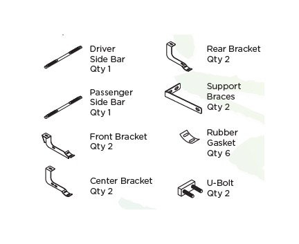
Components:
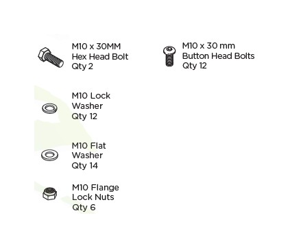
Hardware:
Torque Specifications:
For Cab Mount Installations
Cab mount bolts are torqued to 70 Ft Lbs. All other M8 through M12 sized bolts/nuts are set to 15-20 ft lbs.
Note: When installing the brackets and bars, all hardware must be left loose until all the items are attached.
1. Remove all contents from the package and check the tubes for any damage. Also, verify that all compo-nents and hardware listed above are included before you begin installation.
2. Read installation manual and installation drawing completely. Understand all brackets and bolts before installation.
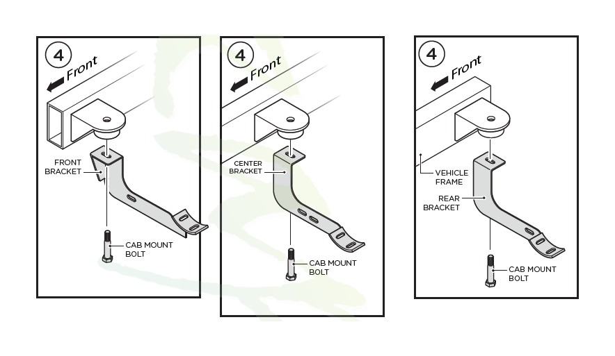
3. Begin installation on drivers side by removing the existing Cab Mount Bolts located underneath the cab of the vehicle.
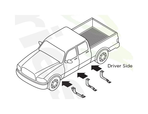
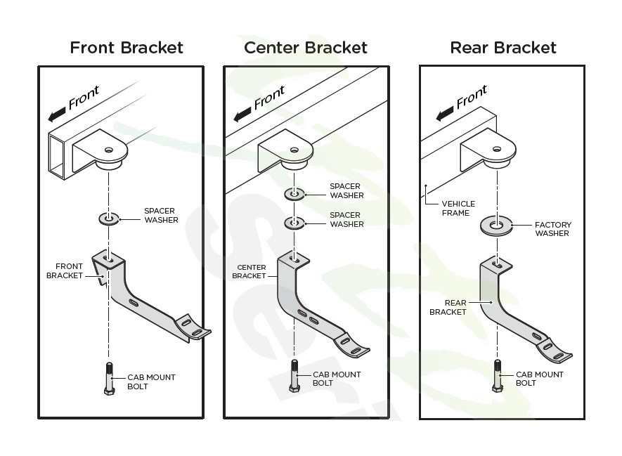
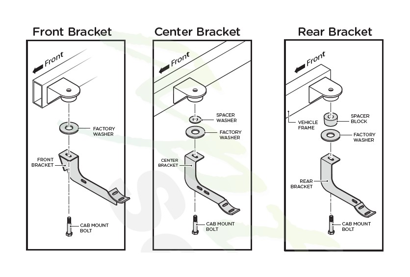
4. Install the Front, Center and Rear Brackets by using the Existing Cab Mount Bolts that you removed in step 3.
Note: Make sure factory bushing is put on the same way it is taken off.
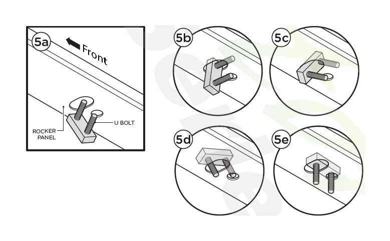
5. Insert the U-Bolt into the larger of the two holes found in the Rocker Panel above the Center Bracket.
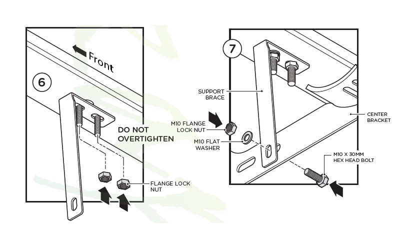
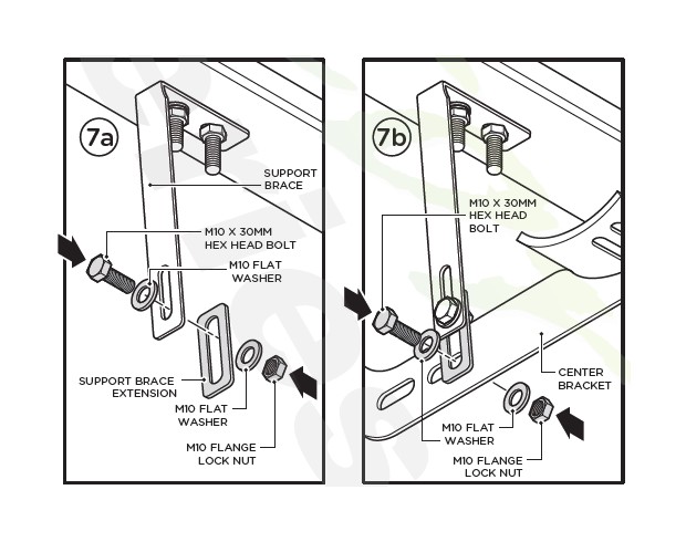
6. Loosely attach the Support Brace to the U Bolt using two (2) M10 Flange Lock Nuts.
7. Fasten the Support Brace to the Center Bracket using one (1) M10 x 30MM Hex Head Bolt, one (1) M10 Flat Washer and one (1) M10 Flange Lock nut.
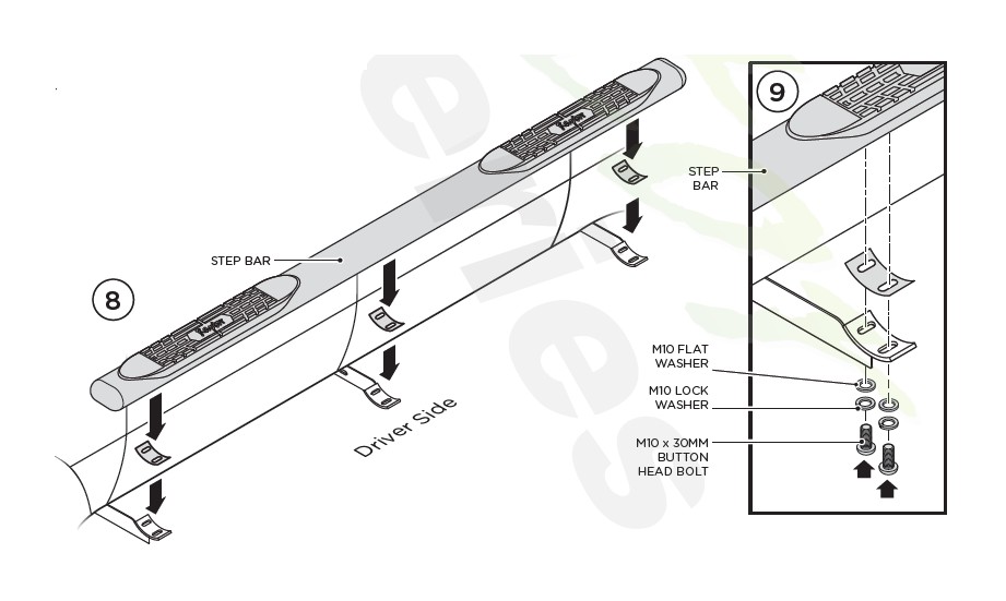
8. Place the Step Bar and the Rubber Gaskets onto the Brackets as shown.
9. Secure the Step Bar to each Bracket using two (2) M10 x 30MM Button Head Screws and two (2) M10 Lock Washers and two (2) M10 Flat Washers per bracket.
Tighten until the split lock washer is flat against bracket and snug. DO NOT over tighten and strip the threaded insert in the tube.
Repeat these steps for passenger side installation. When all hardware is in place, everything must be tightened. See Page 1 for Torque Specifications.
For 2014 Current Chevy/GMC Double Cab 1500 Model
Place Spacer Washers as shown in the diagram below.
DO NOT use pneumatic or electric impact on Cab Mount Bolts.
Step 7 Alternate
Use the Support Brace Extention if the Support Brace is not long enough.
NOTE: Center Bracket removed from illustration for clarity.
For 2015 Current Chevy/GMC Double Cab 2500-3500 Model
Place Spacer Washers as shown in the diagram below.
DO NOT use pneumatic or electric impact on Cab Mount Bolts.