FREE 1 to 3-Day Delivery on Orders $149+ Details
How to Install Air Lift Performance SlamAir Adjustable Air Springs for 2-4 in. Drop (97-03 All) on your Ford F-150
Installation Time
2 hours
Tools Required
- 1/2", 3/4", 7/16", and 1-1/16" open-end or box wrenches
- Ratchet with 3/8", 9/16" and 1/2" deep well sockets
- 3/8" Drill Bit (very sharp)
- 3/8" Nut Driver
- Heavy Duty Drill
- Torque Wrench
- Hose Cutter, Razor Blade, or Sharp Knife
- Hoist or Floor Jacks
- Safety Stands
- Safety Glasses
- Air Compressor, or Compressed Air Source
- Spray Bottle with Dish Soap/Water Solution
Before You Start
You need to determine Ride Height. Ride Height is the distance between the bottom edge of the wheelwell and the center of the hub with the vehicle in lowered condition. In some cases, Ride Height is not perfectly level.
Remove unusual loads and examine your vehicle from the side to ensure it is on a level surface. If necessary (in cases where your leaf springs are sagging badly), use a jack to raise the rear end so that the vehicle achieves the lowered ride height.
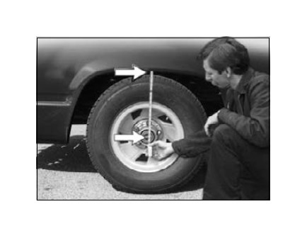
Measure the distance between the center of the hub and the bottom edge of the wheel well. This is the Ride Height. Enter the measurement below:
RIDE HEIGHT: ___________inches
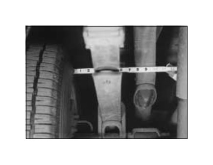
Measure the distance between the frame and the tire. This kit requires a minimum of 5" of clearance for a fully inflated air spring.
IMPORTANT: Your vehicle may be equipped with a rear brake proportioning valve. Any type of load assist product could affect brake performance. We recommend that you check with your dealer before installing this type of product. If your vehicle DOES NOT have a rear brake proportioning valve or is equipped with an anti-lock type brake system, installation of a load assist product will have NO EFFECT ON BRAKE SYSTEM PERFORMANCE.
Compressed air can cause injury and damage to the vehicle and parts if it is not handled properly. For your safety, do not try to inflate the air sleeves until they have been properly secured to the vehicle.
Raising the Vehicle
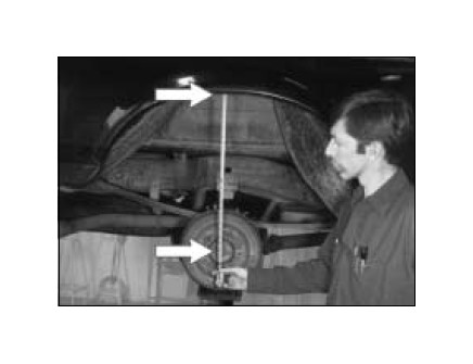
Raise the vehicle and remove the wheels. Check the distance between the center of the hub and the bottom edge of the wheel well to ensure it is at the ride height recorded on page 2. If not, raise the frame or lower the axle as necessary to restore the original distance.
If the vehicle is raised with an axle contact hoist, place stands under the frame and lower the axle as needed . . .
or . . .
If the vehicle is raised with a frame contact hoist, place stands under the axle and lower the frame as needed . . .
or . . .
If the vehicle was raised with a jack and supported with stands on the frame, use a floor jack to raise the axle.
NOTE: This is a universal kit for custom applications. In no way should the sleeve or any of the kit’s components be the suspension limiter in compression or extension. This air spring can compress to 3.0" and extend to 9.1". Regardless of load, the air pressure should be adjusted so that the ride height is maintained at all times. The shock absorber is usually the limiter on extension. If this is not the case, you should consider the use of limiting straps. For technical assistance call Air Lift Technical Service at 1-800-248-0892.
I. Deciding Where to Mount
Due to the wide variety of lowering kits on the market, Air Lift cannot guarantee that this kit will fit every vehicle. You may need to modify the upper bracket, or even weld it, depending on the type of kit the vehicle was lowered with or optional equipment present.
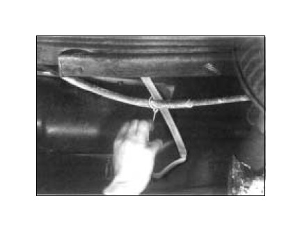
Where you install them will depend on the type of vehicle you have and the placement necessary to avoid brake lines, gas lines, hydraulic lines or other items that may interfere with drilling the upper bracket holes. Some situations, such as vehicles with staggered shock absorbers, may require installing the air springs in front and behind the axle on opposite sides of the vehicle. The installation tool included in your kit will help you check for obstacles and decide which of the installations shown above is the best for your vehicle.
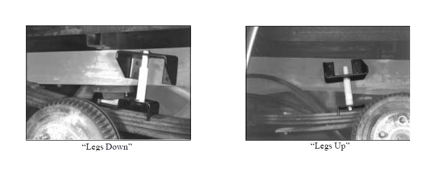
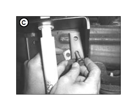
On some models it may be necessary to invert the upper bracket in a “legs up” position to achieve the correct mounting position. Do not “hang” axle on a frame contact hoist while checking this step for proper placement of upper bracket (C). Vehicle suspension must be in custom ride height condition (like sitting in a parking lot).
II. Assemble the Installation Tool
The tool provided with your kit will help you properly align the air spring and position the upper bracket for drilling the bolt holes. The tool attaches to the upper and lower bracket. The tool is rigid so that it will self-align the upper bracket. The threaded section of the upper part of the tool ensures that the air spring can only be mounted at the correct height.
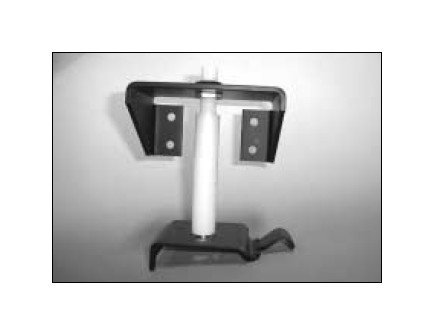
LOOSELY attach the tool (B) to the lower bracket (D) using 1/2" Flat Washer (M) and 1/2" Hex Head Cap Screw 7/8" (L). Leave loose for adjustment.
The upper bracket can be attached to the tool either “legs down” or “legs up” whichever correctly positions the upper bracket on the frame rail.
Secure the upper bracket (C) to the tool (B) using the provided nylon nut (F).
III. Attaching the Lower Bracket
NOTE: See special instructions on Dodge, Ford, and Sierra/Silverado before proceeding with installation.
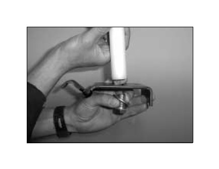
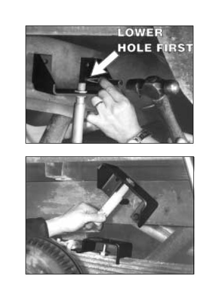
Set the assembled bracket/tool unit on the leaf spring.
With the hook end of the lower bracket placed over the U-bolt or edge of the upper spring retaining plate, secure the lower bracket to the leaf spring with the provided U-bolt (G), lower clamp bar (E), 3/8" flat washers (I), and locknuts (K). Torque to 16 ft/lbs. Note: The bracket will pull down flat to the leaf spring when the locknuts are tightened.
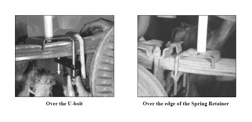
NOTE: It is important that the “finger” on the lower bracket “hooks” around U-bolt or Spring Retainer so it does not “walk” up the spring.
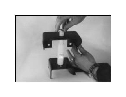
IV. Mounting the Upper Bracket
NOTE: See special instructions on Dodge, Ford, and Sierra/Silverado before proceeding with installation.
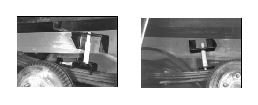
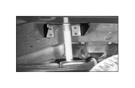
Using the slot in the lower bracket, push the upper bracket against the frame rail. Use the Pal nut on the threaded portion of the installation tool and a supplied nylon nut to adjust the upper bracket so that the legs of the upper bracket are flat against the frame rail and all four mounting holes are on the middle section of the frame rail. The mounting holes must stay 3/4" from the rounded edges of the frame rail. You must also allow at least 1.5" above the top of the upper bracket for air fitting clearance. The brackets can be mounted anywhere within the threaded range of the installation tool. On some models it may be necessary to invert the upper bracket in a “legs up” postition to achieve the correct mounting position.
Before drilling, check the back side of the frame to see if brake lines, gas lines, or other features will have to be moved before you drill the upper bracket holes. Always check the back side of any surface to be drilled.
NOTE: See Silverado/Sierra Special Instructions.
‘99 SILVERADO / SIERRA SPECIAL INSTRUCTIONS
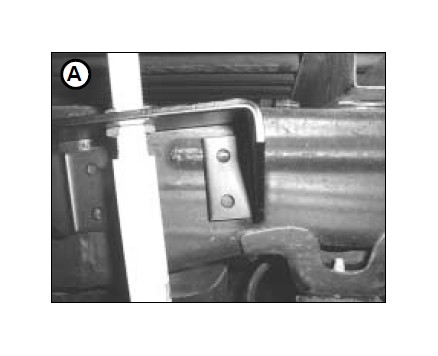
Adjust the upper bracket along the threaded tool until the upper rearward hole lines up squarely on the ridge as shown in Figure A.
Not all ‘99 Silverado/Sierra models have this reinforcing frame ridge. If yours does not, place bracket in same position and follow same installation instructions.
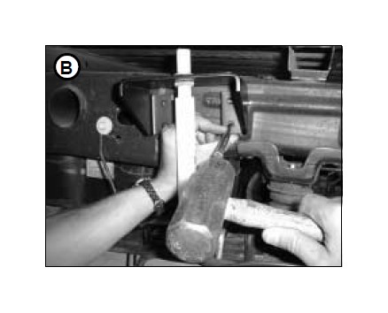
Center punch the lower rear hole and drill a 3/8" hole (Figure B).
Insert the square spacer (N) between the upper bracket and the frame as shown in Figure C. Loosely attach frame bolt (O), large washer (J) and nut (K).
Center punch the forward lower hole, and drill a 5/16" hole (Figure D).
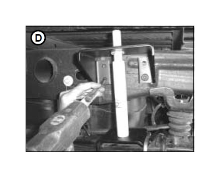
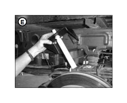
Remove tool by removing lower attaching bolt and upper nylon nut (F). Swing upper bracket down to remove tool (Figure E).
Attach upper bracket at forward lower hole with a self-tapping bolt (H). Tighten rear lower hole frame bolt securely.
Centerpunch and drill remaining two upper holes. Be sure to drill a 5/16" hole in the forward upper hole and attach with a self-tapping bolt (H). Drill a 3/8" hole in the rear upper hole, attaching with frame bolt (O), large washer (J) and nut (K).
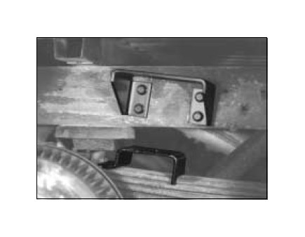
Using the upper bracket as a template, centerpunch one of the lower mounting holes and drill a 3/8" hole through the frame. Install one of the mounting bolts (O) and LOOSELY attach the oversized flat washer (J) and locknut (K). Now centerpunch and drill a 3/8" hole at the OTHER LOWER mounting hole location. DO NOT insert the mounting bolt at this time.
You can now remove the installation tool by removing the upper pal nut, loosening and removing the tool from the bottom bolt (leave in place), and slightly rotating the upper bracket to give you enough room to completely remove the tool.
Save the upper nylon nut to attach the air spring as shown on page 10.
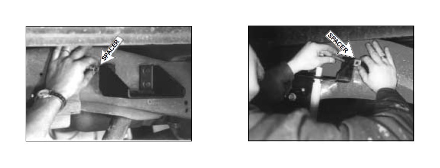
DODGE AND FORD - NOTE: MANY DODGE AND FORD PICKUP CHASSIS HAVE AN INDENT IN THE FRAME RAIL. IT IS NECESSARY TO USE THE PROVIDED SPACERS BEHIND THE MOUNTING HOLES IN THE UPPER BRACKET THAT FALL INTO THE INDENTED AREA. USE TWO ROUND SPACERS (P) FOR THE DODGE AND ONE SQUARE SPACERS (N) FOR THE FORD PER SIDE.
Rotate the upper bracket back to the original location and install the washer head frame bolt (O), 3/8" Oversized flat washer (J), and lock nut (K) through the second hole you drilled. Now tighten both of the installed fasteners to 20 ft/lbs.. Center punch and drill the other two holes and install the fasteners. Torque all fasteners to 20 ft. lbs.
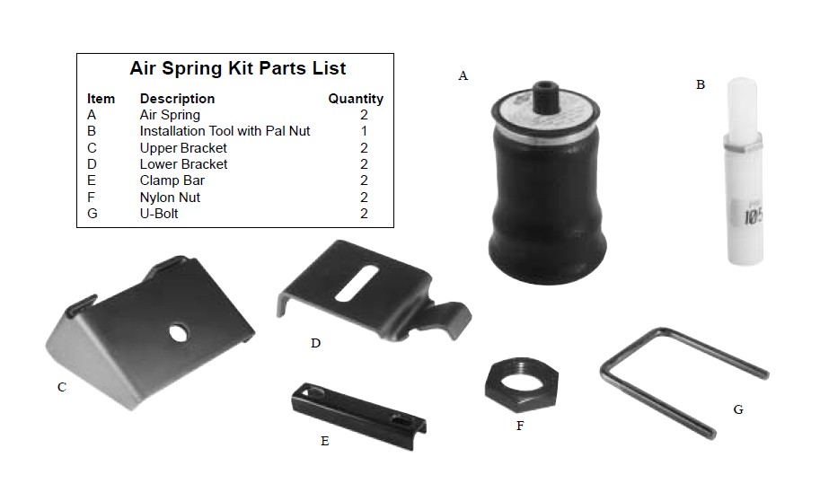
V. Mounting the Air Spring
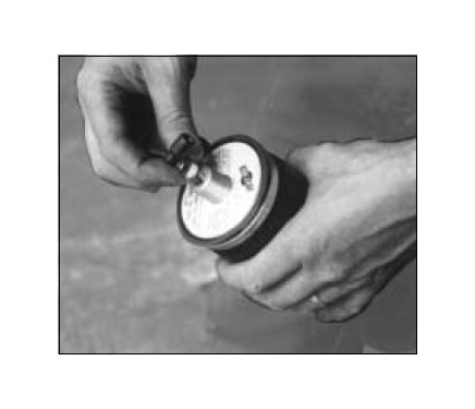
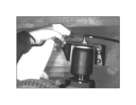
Install the air fitting (Q) into the top of the air spring (A). This fitting is pre-coated with sealant. Finger-tight plus one and a half turns with an open-end wrench will seal the fitting. Use a 7/16" open end wrench being careful to tighten on the metal hex nut only. DO NOT OVERTIGHTEN.
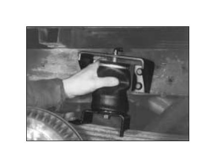
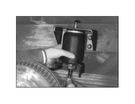
Collapse the air spring and guide upper end through the center mounting hole in the upper bracket.
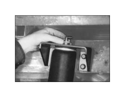
Now install the Pal Nut (F) - flange up - onto the upper threadpost of the air spring. LEAVE LOOSE for final adjustment.
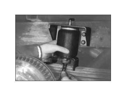
Attach the air spring to the lower bracket. Carefully hold the lower mounting bolt (K) with a 1-1/16" open end wrench and hand turn the air spring onto the lower mounting bolt (K). LEAVE LOOSE for later adjustment.
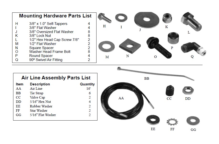
VI. Installing the Air Lines
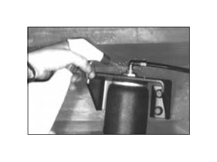
Choose a convenient location for mounting the inflation valves. Make sure there is enough clearance around the valves for an air chuck. Drill a 5/16" hole to install the valves.
Popular locations for the valve are:
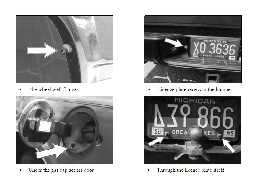
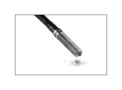
Cut the air line in two equal lengths.
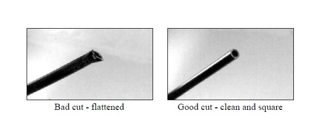
When cutting or trimming the air line, use a hose cutter (Air Lift P/N 10530), a razor blade or a sharp knife. Do not use wire cutters or scissors to cut the air line. These tools may flatten or crimp the air line, causing it to leak around the O-ring seal inside the swivel fitting.
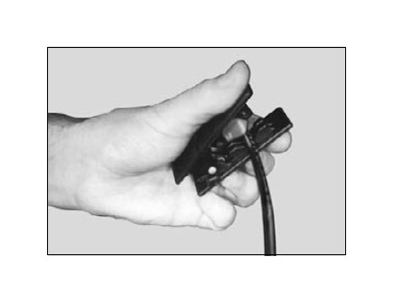
Do not use wire cutters or scissors to cut the air line. These tools may flatten or crimp the air line, causing it to leak around the O-ring seal inside the elbow fitting.
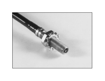
Place a 5/16" nut (DD) and a star washer (FF) on the air valve. Leave enough of the inflation valve in front of the nut to extend through the hole and have room for the rubber washer (EE), flat washer (GG), 5/16" nut (DD) and cap (CC). There should be enough valve exposed after installation - approximately 1/2" - to easily apply a pressure gauge or an air chuck.
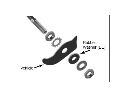
Push the air valve through the hole and use the rubber washer (EE), flat washer (GG) and another 5/16" (DD) nut to secure it in place. Tighten the nuts to secure the assembly in place.
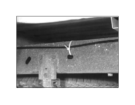
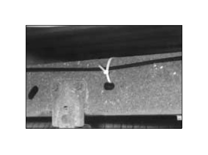
Route the air line along the frame to the swivel fitting. Keep at least 6" of clearance between the air line and heat sources, such as the exhaust pipes. Avoid sharp bends and edges. Use the plastic tie straps (BB) to secure the air line to fixed, non-moving points along the chassis. Be sure that the tie straps are tight, but do not pinch the air line. Leave at least 2" of slack to allow for any movement that might pull on the air line. Trim the excess air line before inserting it into the swivel fitting.
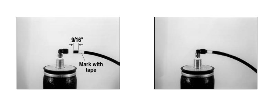
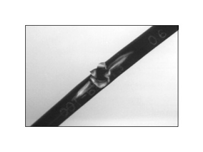
To properly install the air line measure 9/16" from the cut end and mark with tape. Lubricate (i.e., soap solution, silicone spray, saliva) the end of the air line and insert it into the fitting. Push and slightly turn the air line until you hear/feel it “click” into place. The front edge of the tape band should be flush with the fitting. The air line is now installed.
VII. Aligning the Air Spring
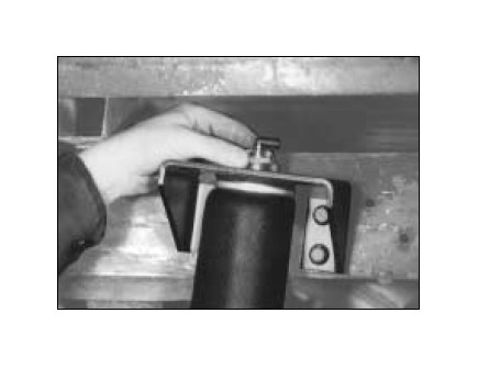
VERY IMPORTANT - With the bottom and top of the air spring still loose, inflate to approximately 10 p.s.i.. Use the slotted adjustment in the lower bracket to correctly align the air spring between the upper and lower bracket. This can be accomplished by tapping it inboard or outboard for proper alignment. There should be a symmetrical cushion of air around the base of the air spring when correctly positioned. With the top still loose, tighten the lower bolt securely (10 ft. lbs.).
Now tighten the upper nylon nut with 1 1/16" open end wrench (4 ft.lbs.). DO NOT OVER TIGHTEN.
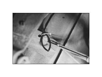
Driver Side-It may be necessary to secure the emergency brake cable away from the air spring to prevent it from rubbing. Use the provided tie straps (BB).
VIII. Install Other Air Spring
You have now completed the installation for one air spring. Complete steps I - V for the other side, and then return to step VII.
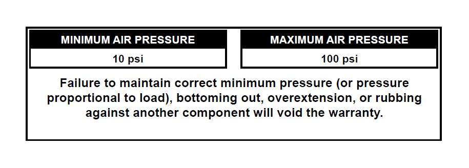
IX. Inflation Decal
Install the minimum/maximum air pressure decal in a highly visible location. We suggest placing it on the driver’s side window, just above the door handle.
X. Checking for Leaks
Inflate the air spring to 60 p.s.i. Spray all connections, fittings and the inflation valves with a solution of 1/5 liquid dish soap and 4/5 water to check for leaks. You should be able to spot leaks easily by observing any bubbling in the soapy water. After the test, deflate the springs to the minimum pressure required to restore the Normal Ride Height, but not less than 10 p.s.i.
Check the air pressure again after 24 hours. A 2 to 4 p.s.i. loss after initial installation is normal. Retest for leaks if the loss is more than 5 lbs.
XI. Fixing Leaks
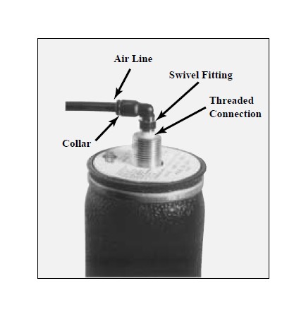
Swivel Fitting
1. Air Line Connection Deflate the spring and remove the line by pulling the collar against the fitting and pulling firmly on the air line. Trim 1/2" off the end of the air line. Be sure the cut is clean and square. Reinsert the air line into the push-to-connect fitting.
Inflation Valve
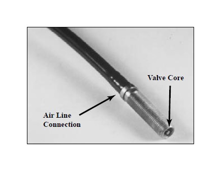
1. Valve Core
Tighten the valve core with a valve core tool.
2. Air Line Connection
When removing air line from a barbed type fitting, DO NOT CUT IT OFF as this will usually nick the barb and render the fitting useless. Cut air line off a few inches in front of the fitting and use a pair of pliers or vise-grips to pull/twist the air line off the fitting.
If the preceding steps have not resolved the problem, call Air Lift Technical Service at 1-800-248-0892 for assistance.
X. Checklist
You can protect your warranty on this product and prevent unnecessary wear by ensuring the following checks have been made:
Section I - Installation (To be completed by the installer).
1. Clearance Test - Inflate the air springs to 60 p.s.i. and ensure there is at least 1/2" clearance around each sleeve from anything that might rub against them. Be sure to check the tire, brake drum, frame, shock absorbers and brake cables.
2. Leak Test Before Road Test - Inflate the air springs to 60 p.s.i., check all connections for leaks with a soapy water solution. See page 14 of the manual for tips on how to spot leaks. All leaks must be eliminated before the vehicle is road tested.
3. Heat Test - Be sure there is sufficient clearance from heat sources - at least 6" for air springs and air lines. If a heat shield was included in the kit - install it. If there was no heat shield, but one is required, call 1-800-248-0892.
4. Fastener Test - Recheck all bolts for proper torque.
Torque Guide:
3/8" Frame Bolts 20 ft.-lbs.
Lower mounting bolt for air spring 10 ft.-lbs.
Upper Nylon Nut for air spring 4 ft.-lbs.
5. Road Test - The vehicle should be road tested after the preceding tests. Inflate the springs to 10 p.s.i. or until vehicle is level. Drive the vehicle 10 miles and recheck for clearance, loose fasteners and/or air leaks.
6. Operating Instructions - If professionally installed, the installer should review the operating instructions on page 17 with the owner. Be sure to provide the owner with all of the paperwork that came with the kit.
Section II - Post Installation Checklist (TO BE COMPLETED BY OWNER)
1. Overnight Leakdown Test - Recheck air pressure after vehicle has been used for 24 hours. If pressure has dropped more than 5 p.s.i., you have a leak that must be fixed. Either fix the leak yourself (see page 14) or return to the installer for service.
2. Air Pressure Requirements - I understand that the air pressure requirements of my air spring system are as follows:
Minimum ___________ Maximum ___________
I also understand that I must inflate the air springs until the Normal Ride Height measurement that was recorded on page 2 has been restored. Regardless of load, the air pressure should always be adjusted so that the Ride Height is maintained at all times.
3. Thirty Day or 500 Mile Test. I understand that I must recheck the air spring system after 30 days or 500 miles, whichever comes first. If any part shows signs of rubbing or abrasion, the source should be identified and moved, if possible. If it is not possible to relocate the cause of the abrasion, the air spring may need to be remounted. If professionally installed, the installer should be consulted. Check all fasteners for tightness.
Maintenance and Operations
By following these steps, vehicle owners should obtain the longest life and best results from their air springs.
1. Check the air pressure in the air springs weekly.
2. Always maintain Normal Ride Height. Never inflate beyond 100 p.s.i.
3. If you develop an air leak in the system, use a soapy water solution to check all air line connections and the inflation valve core before deflating and removing the air spring. (See page 17.)
4. Always adjust the air pressure to maintain the Normal Ride Height. Increase or decrease pressure from the system as necessary to attain Normal Ride Height for optimal ride and handling. Remember that loads carried behind the axle (including tongue loads) require more leveling force (pressure) than those carried directly over the axle.
5. IMPORTANT: For your safety and to prevent possible damage to your vehicle, do not exceed maximum Gross Vehicle Weight Rating (GVWR), as indicated by the vehicle manufacturer. Although your air springs are rated at a maximum inflation pressure of 100 p.s.i., the air pressure actually needed is dependent on your load and GVWR, which may be less than 100 p.s.i. Check your vehicle owners manual or the manufacturers specification plate usually found on the inside door jamb, and do not exceed the maximum load listed for your vehicle.
6. Always add air to springs in small quantities, checking the pressure frequently. Air springs require less air volume than a tire and inflate quickly.
7. Should it become necessary to raise the vehicle by the frame, make sure the system is at minimum pressure (5 p.s.i.) to reduce the tension on the suspension/brake components.
Troubleshooting Guide
1. Problems maintaining air pressure
WITHOUT ON-BOARD COMPRESSOR
Leak test the air line connections and threaded connection of the elbow into the air spring. See page 14 to repair.
Leak test the inflation valve for leaks at the air line connection or dirt or debris in the valve core. See page 14 for repair
Inspect air lines to be sure it is not pinched. Tie straps may be too tight. Loosen or replace strap. Replace leaking components.
Inspect air line for holes and cracks. Replace as needed.
A kink or fold in the air line. Re-route as needed.
You have now tested for all of the most probable leak conditions that can be easily fixed. At this point the problem is probably a damaged air spring - either a factory defect or an operating problem. We suggest that you return the vehicle to your installer. If self-installed or you are the professional installer, please call Air Lift at 1-800-248-0892 for assistance or a replacement air spring.
Notes
You may find this space useful for recording information about your system (i.e., weekly pressure readings). Also record any information from your installer or Air Lift technical assistance personnel.
Tuning the air pressure
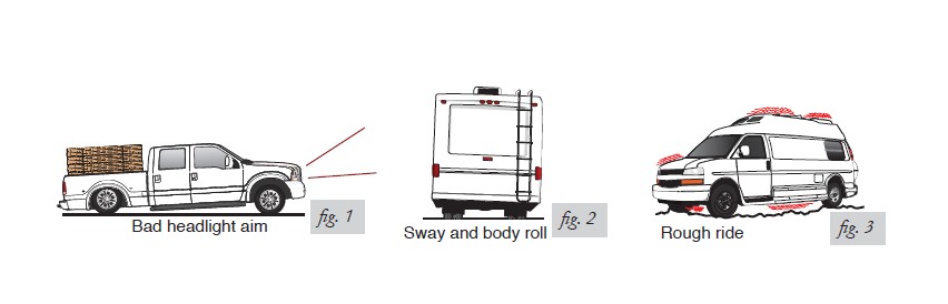
Pressure determination comes down to three things — level vehicle, ride comfort, and stability.
1. Level vehicle
If the vehicle’s headlights are shining into the trees or the vehicle is leaning to one side, then it is not level (fig. 1). Raise the air pressure to correct either of these problems and level the vehicle.
2. Ride comfort
If the vehicle has a rough and harsh ride it may be due to either too much pressure or not enough (fig. 2). Try different pressures to determine the best ride comfort.
3. Stability
Stability translates into safety and should be the priority, meaning the driver may need to sacrifice a perfectly level and comfortable ride. Stability issues include roll control, bounce, dive during braking and sponginess (fig. 3). Tuning out these problems usually requires an increase in pressure.
Guidelines for adding air:
1. Start with the vehicle level or slightly above.
2. When in doubt, always add air.
3. For motorhomes, start with 50-100 PSI in the rear because it can be safely assumed that it is heavily loaded.
4. If the front of the vehicle dives while braking, increase the pressure in the front air bags, if equipped.
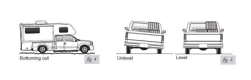
5. If it is ever suspected that the air bags have bottomed out, increase the pressure (fig. 4).
6. Adjust the pressure up and down to find the best ride.
7. If the vehicle rocks and rolls, adjust the air pressure to reduce movement.
8. It may be necessary to maintain different pressures on each side of the vehicle. Loads such as water, fuel, and appliances will cause the vehicle to be heavier on one side (fig. 5). As much as a 50 PSI difference is not uncommon.