FREE 1 to 3-Day Delivery on Orders $149+ Details
How to Install Air Lift Performance RideControl (15-18 All, Excluding Raptor) on your Ford F-150
Installation Time
2 hours
Tools Required
- Hoist or floor jack
- Safety stands
- Safety glasses
- Torque wrench
- Standard open-end combo wrenches
- Medium size adjustable wrench
- Ratchet
- Metric and standard sockets
- 5/16” drill bit (very sharp)
- Heavy duty drill
- Bench or hand grinder
- Black spray paint
- Hose cutter, razor blade, or sharp knife
- Air compressor or compressed air source
- Spray bottle with dish soap/water solution

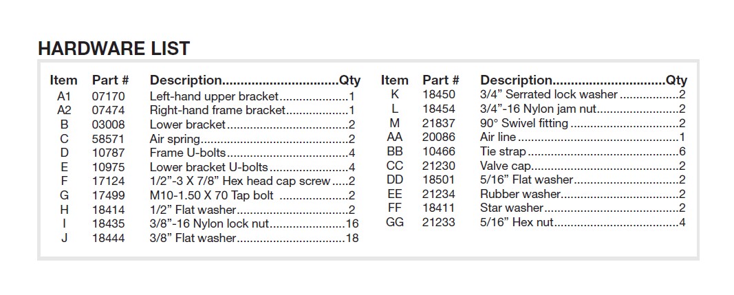
Shop Parts in this Guide
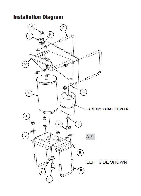
Installation Diagram
Installing the RideControl System
INSTALLING THE UPPER BRACKETS
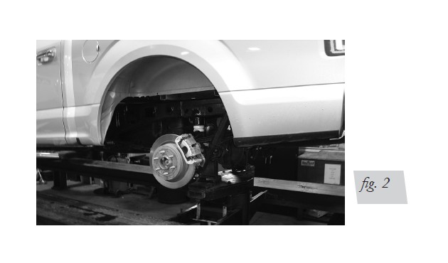
1. Jack the vehicle up and support the axle with safety stands. Remove the rear wheels
(fig. 2).
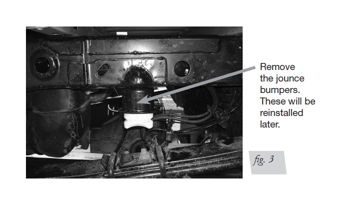
2. Unbolt and remove the jounce bumpers (these will be reinstalled later) (fig. 3).
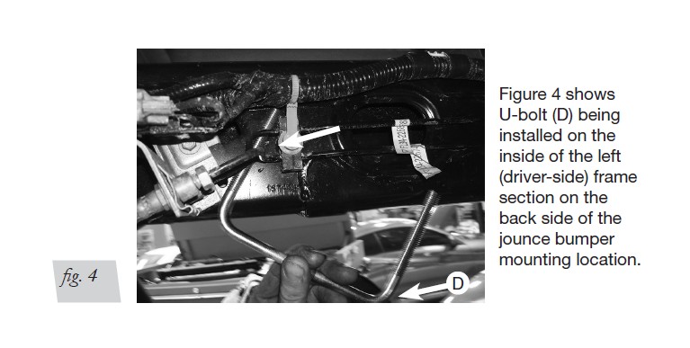
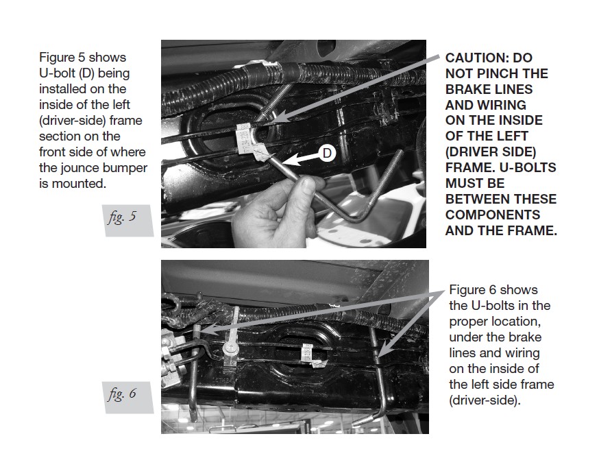
3. Set the frame U-bolts (D) around the frame from the inside-out on both sides of the vehicle-ahead of and behind where the jounce bumper is mounted. Figure 6 shows both U-bolts installed between the brake lines and wiring. Repeat U-bolt installation for the right side (passenger side).
CAUTION: DO NOT PINCH THE BRAKE LINES AND WIRING ON THE INSIDE OF THE LEFT (DRIVER SIDE FRAME). U-BOLTS MUST BE BETWEEN THESE COMPONENTS AND THE FRAME (FIGS. 4, 5, AND 6).
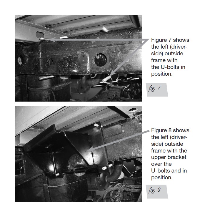
4. With the U-bolts into position, set the left (A1) and right (A2) upper bracket against the frame while aligning the U-bolts (fig. 7) through the mounting holes in the bracket (fig. 8).
5. Cap the U-bolts with four 3/8” flat washers (J) and 4 x 3/8” nylon lock nuts (I) (fig. 1).
Leave loose at this time.
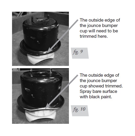
6. In order to make sufficient clearance for the flex member (the rubber part) on the air
spring, it will be necessary to trim the edge of the bracket off on the outside flange
of the jounce bumper cup (steel portion). Do this by grinding the flange flush with
the rest of the cup (figs. 9 and 10). Spray black paint on the bare metal surface once
complete. Repeat for both sides.
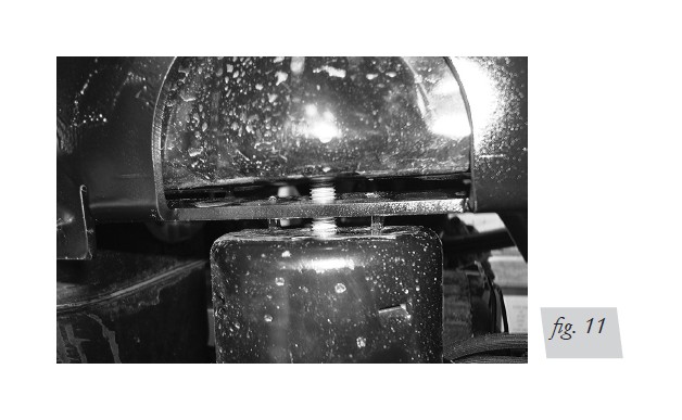
7. Insert the M-10 tap bolt (G) through a flat washer (J) and then through the jounce
bumper (fig. 1). Using the center hole in the bottom flange of the upper bracket,
install this assembly back onto the bottom frame flange in the location from which
it was removed, making sure the edge that was ground off faces the outside of the
vehicle (fig. 11). Tighten the bolt so that the bracket just touches the frame at this
time. Do not tighten or torque yet. Repeat for the opposite side.
CAUTION: MAKE ONE LAST CHECK THAT THE U-BOLTS ON THE INSIDE OF THE LEFT FRAME (DRIVER SIDE) ARE NOT PINCHING THE BRAKE LINES OR THE WIRING. ADJUST IF NECESSARY AT THIS POINT.
8. With the upper bracket flush to the bottom frame flange from the last step, torque the
frame U-bolts evenly to 10 lb.-ft. (14Nm). Once this is done and the bracket is flush
against the frame, torque the jounce bumper bolt to 30 lb.-ft. (41Nm). Repeat for the
other side.
ASSEMBLING THE AIR SPRING ASSEMBLY
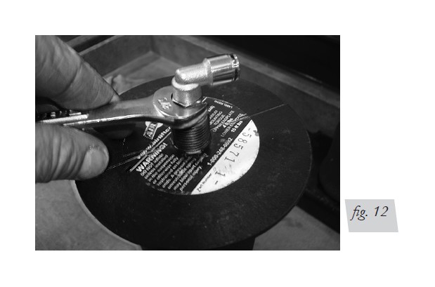
1. Install the fitting (M) onto the top port of the air spring (C) (fig. 12) finger-tight plus
1-1/2 turns. Repeat for both air springs.
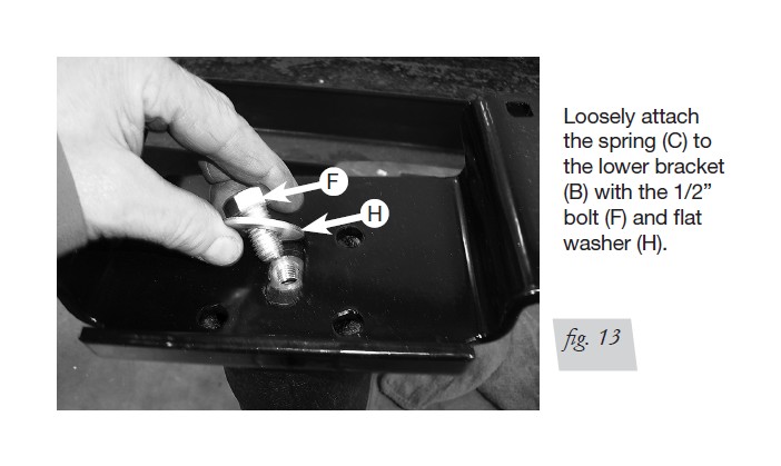
2. Install the air springs (C) to the lower brackets (B) using the 1/2” bolt (F) and flat
washer (H) (figs. 1 and 13). Leave loose at this time.
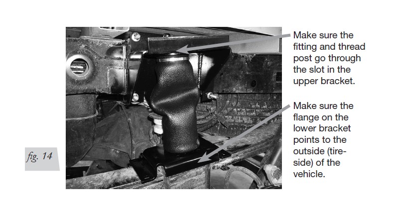
3. Set the assemblies onto the leaf spring making sure the upper fitting and thread post
on the air spring goes through the slot in the upper bracket. The flange on the lower
bracket points to the outside (tire-side) of the vehicle (fig. 14).
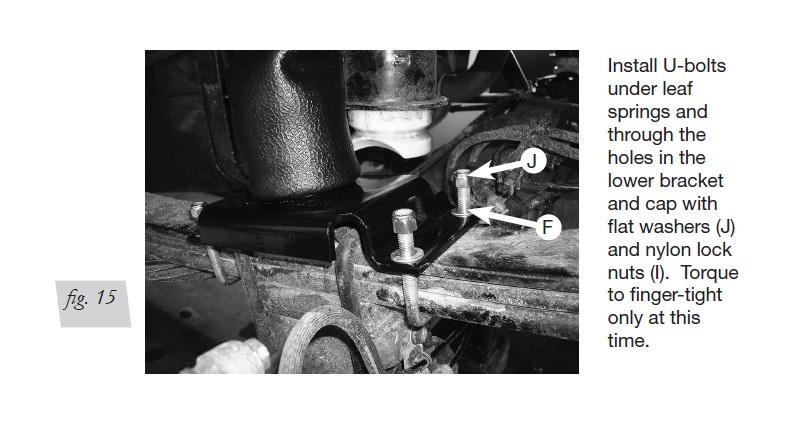
4. Set the lower bracket U-bolts (E) under the leaf springs and through the holes in the
lower bracket (fig. 15) and cap with four 3/8” flat washers (J) and 3/8” nylon lock
nuts (I). Torque to finger-tight only at this time.
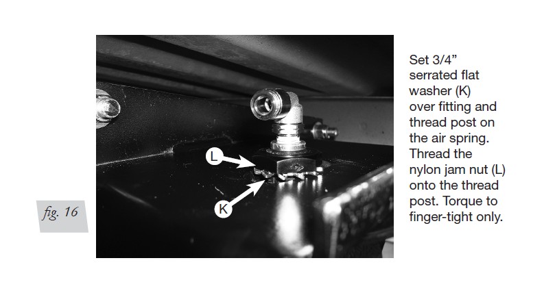
5. Install the upper air spring hardware by setting the 3/4” serrated lock washer (K)
over the fitting and thread post (fig. 16). Set the 3/4” nylon lock jam nut (L) over the
fitting (with the flat side down) and thread onto the post. Torque to finger-tight only
at this time.
Installing Air Lines
1. Choose a convenient location for mounting the inflation valves. Popular locations for
the inflation valve are:
a. The wheel well flanges
b. The license plate recess in bumper
c. Under the gas cap access door
d. Through the license plate
NOTE: Whatever the chosen location, make sure there is enough clearance around the inflation valves for an air chuck.
2. Drill two 5/16” holes to install the inflation valves.
3. Cut the air line assembly in two equal lengths.
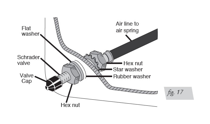
4. Place a 5/16” nut and star washer on the air valve. Leave enough of the inflation
valve in front of the nut to extend through the hole and have room for the rubber
washer, flat washer, and 5/16” nut and cap. There should be enough valve exposed
after installation – approximately 1/2” – to easily apply a pressure gauge or an air
chuck. (Fig. 17.)
5. Push the inflation valve through the hole and use the rubber washer, flat washer and another 5/16” nut to secure it in place. Tighten the nuts to secure the assembly.
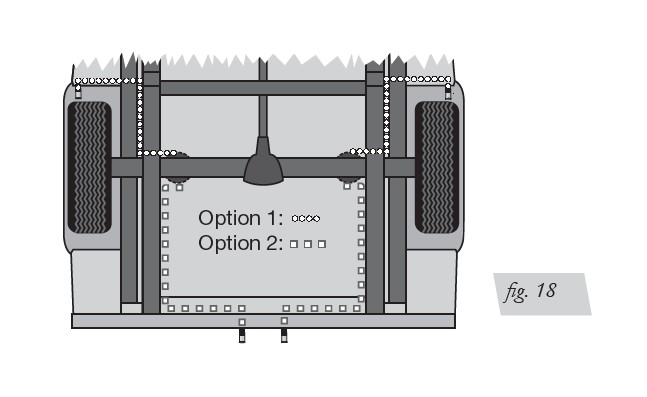
6. Route the air line along the frame to the air fitting on the air spring (Fig. 18). Keep AT LEAST 6” of clearance between the air line and heat sources, such as the exhaust pipes, muffler, or catalytic converter. Avoid sharp bends and edges. Use plastic tie straps to secure the air line to fixed points along the chassis. Be sure that the tie straps are tight, but do not pinch the air line. Leave at least 2” of slack to allow for any movement that might pull on the air line.
7. Cut off the air line, leaving approximately 12” of extra air line. A clean square cut will prevent leaks. Insert the air line into the air fitting. This is a push-to-connect fitting. Simply push the air line into the 90-degree swivel fitting until it bottoms out (9/16” of air line should be in the fitting).
TIPS FOR INSTALLING AIR LINES
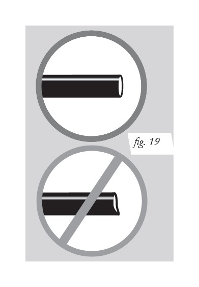
When cutting air lines, use a sharp knife or a hose cutter and make clean, square cuts (Fig. 19). Do not use scissors or wire cutters because these tools may deform the air line, causing it to leak around fittings. Do not cut the lines at an angle.
Do not bend the 1/4” hose at a radius of less than 1” or bend the 3/8” hose at a radius of less than 1 1/2”. Do not put side load pressure on fitting. The hose should be straight beyond the fitting for 1” before bending.
Inspect hose for scratches that run lengthwise on hose prior to installation. Contact Air Lift customer service at (800) 248-0892 if the air line is damaged.
ALIGNING AND FINISHING THE INSTALLATION
1. With the mounting hardware and hose assembly in place, inflate the air spring to
5 PSI (only) at this time.
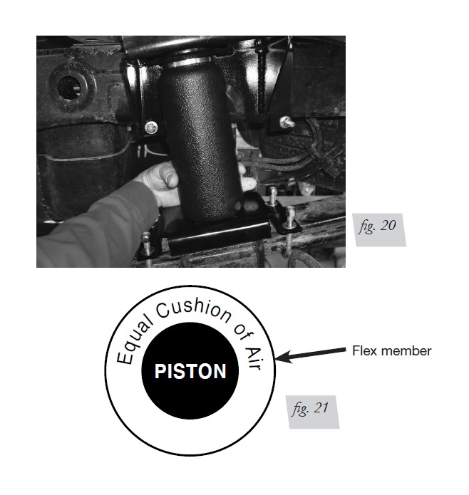
2. Adjust the spring so that it is perpendicular to both top and bottom brackets by
using the slot in the top and bottom mounts. Pinch the flex member at the bottom
around the piston (figs. 20 and 21). There should be a symmetrical cushion of air
around the flex member and piston.
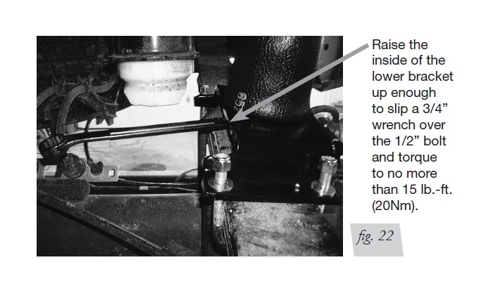
3. You will need to adjust and tighten the bottom of the air spring first. In order to
do this, mark the location of the bottom piston in reference to the lower bracket.
Deflate the air pressure from the air spring and raise the inside of the lower bracket
up enough to slip a 3/4” open end wrench onto the 1/2” bolt, which is attaching the
spring to the lower mount (fig. 22). Tighten the bolt no more than 15 lb.-ft. (20Nm).
Repeat for the opposite side.
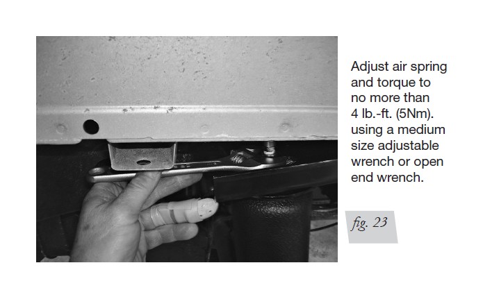
4. Once the lower is set, inflate the air springs back to 5 PSI and, if necessary, readjust
the upper spring forward or back in the slot. Using a medium adjustable wrench or
an open end wrench, tighten the nylon jam nut to no more than 4 lb.-ft. (5Nm) (just
snug) (fig. 23). Repeat for the other side.
5. Once the air spring has been properly aligned, torque the lower mounting hardware
on the lower bracket U-bolts to 15 lb.-ft. (20Nm). on both sides.
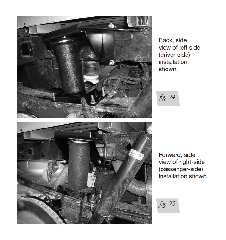
6. Figures 24 and 25 show the left- and right-hand assemblies installed on the vehicle.
7. Install the tires back onto the vehicle and torque to the manufacturers torque
specifications.
Before Operating
CHECKING FOR LEAKS
1. Inflate the air spring to 30 PSI.
2. Spray all connections and the inflation valves with a solution of 1/5 liquid dish soap
and 4/5 water. Spot leaks easily by looking for bubbles in the soapy water.
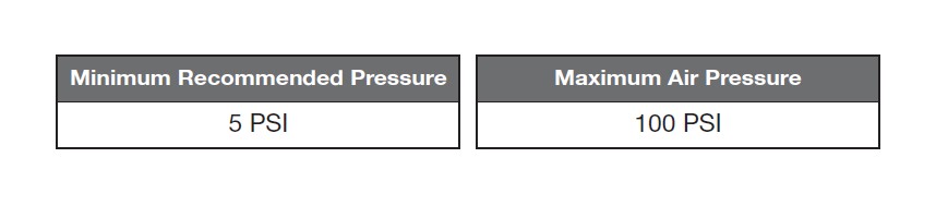
3. After the test, deflate the springs to the minimum pressure required to restore the
system to normal ride height. Do not deflate to lower than 5 PSI.
4. Check the air pressure again after 24 hours. A 2-4 PSI loss after initial installation is
normal. Retest for leaks if the loss is more than 5 PSI.
FIXING LEAKS
1. If there is a problem with the swivel fitting:
a. Check the air line connection by deflating the spring and removing the line by pulling the collar against the fitting and pulling firmly on the air line. Trim 1” off the end of the air line. Be sure the cut is clean and square (see Fig. 35). Reinsert the air line into the push-to-connect fitting.
b. Check the threaded connection by tightening the swivel fitting another half turn. If it still leaks, deflate the air spring, remove the fitting, and re-coat the threads with thread sealant. Reinstall by hand tightening as much as possible and then use a wrench for an additional two turns.
2. If there is a problem with the inflation valve:
a. Check the valve core by tightening it with a valve core tool.
b. Check the air line by removing the air line from the barbed type fitting. Cut the air line off a few inches in front of the fitting and use a pair of pliers or vice grips to pull/twist the air line off of the fitting.
CAUTION: DO NOT CUT OFF THE AIR LINE COMPLETELY AS THIS WILL USUALLY NICK THE BARB AND RENDER THE FITTING USELESS.
3. If the preceding steps have not resolved the problem, call Air Lift customer service at (800) 248-0892.
INSTALLATION CHECKLIST
Clearance test - Inflate the air springs to 75-90 PSI and make sure there is at least 1/2” clearance from anything that might rub against each sleeve. Be sure to check the tire, brakes, frame, shock absorbers and brake cables.
Leak test before road test - Inflate the air springs to 75-90 PSI and check all connections for leaks. All leaks must be eliminated before the vehicle is road tested.
Heat test - Be sure there is sufficient clearance from heat sources, at least 6” for air springs and air lines. If a heat shield was included in the kit, install it. If there is no heat shield, but one is required, call Air Lift customer service at (800) 248-0892. Fastener test - Recheck all bolts for proper torque.
Road test - The vehicle should be road tested after the preceding tests. Inflate the springs to recommended driving pressures. Drive the vehicle 10 miles and recheck for clearance, loose fasteners and air leaks.
Operating instructions - If professionally installed, the installer should review the operating instructions with the owner. Be sure to provide the owner with all of the paperwork that came with the kit.
POST-INSTALLATION CHECKLIST
Overnight leak down test - Recheck air pressure after the vehicle has been used for 24 hours. If the pressure has dropped more than 5 PSI, then there is a leak that must be fixed. Either fix the leak yourself or return to the installer for service.
Air pressure requirements - It is important to understand the air pressure requirements of the air spring system. Regardless of load, the air pressure should always be adjusted to maintain adequate ride height at all times while driving.
Thirty-day or 500-mile test -Recheck the air spring system after 30 days or 500 miles, whichever comes first. If any part shows signs of rubbing or abrasion, the source should be identified and moved, if possible. If it is not possible to relocate the cause of the abrasion, the air spring may need to be remounted. If professionally installed, the installer should be consulted. Check all fasteners for tightness.
Product Use, Maintenance and Servicing
NOTE: By following the steps below, vehicle owners will obtain the longest life and best results from their air springs.
1. Check air pressure weekly.
2. Always maintain normal ride height. Never inflate beyond 100 PSI.
3. If the system develops an air leak, use a soapy water solution (1/5 liquid dish soap and 4/5 water) to check all air line connections and the inflation valve core before deflating and removing the air spring.
CAUTION: FOR SAFETY AND TO PREVENT POSSIBLE DAMAGE TO THE VEHICLE, DO NOT EXCEED MAXIMUM GROSS VEHICLE WEIGHT RATING (GVWR), AS INDICATED BY THE VEHICLE MANUFACTURER. ALTHOUGH THE AIR SPRINGS ARE RATED AT A MAXIMUM INFLATION PRESSURE OF 100 PSI, THE AIR PRESSURE ACTUALLY NEEDED IS DEPENDENT ON LOAD AND GVWR.
4. Loaded vehicles require at least 25 PSI. A “loaded vehicle” refers to a vehicle with a heavy bed load, a trailer or both. Never exceed GVWR, regardless of air spring, air pressure or other load assist. The springs in this kit will support approximately 40 pounds of load (combined on both springs) for each 1 PSI of pressure. The required air pressure will vary depending on the state of the original suspension. Operating the vehicle below the minimum air spring pressure will void the Air Lift warranty.
5. When increasing load, always adjust air pressure to maintain normal ride height. Increase or decrease pressure from the system as necessary to attain normal ride height for optimal ride and handling. Remember that loads carried behind the axle (including tongue loads) require more leveling force (pressure) than those carried directly over the axle.
6. Always add air to springs in small quantities, checking the pressure frequently.
7. Should it become necessary to raise the vehicle by the frame, make sure the system is at minimum pressure (5 PSI) to reduce the tension on the suspension/ brake components. Use of on-board leveling systems do not require deflation or disconnection.
8. Periodically check the air spring system fasteners for tightness. Also, check the air springs for any signs of rubbing. Realign if necessary.
9. On occasion, give the air springs a hard spray with a garden hose to remove mud, sand, gravel or other debris.
TUNING THE AIR PRESSURE
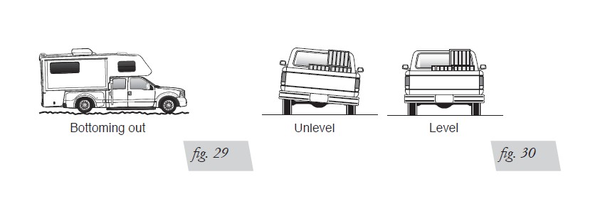
Pressure determination comes down to three things - level vehicle, ride comfort and stability.
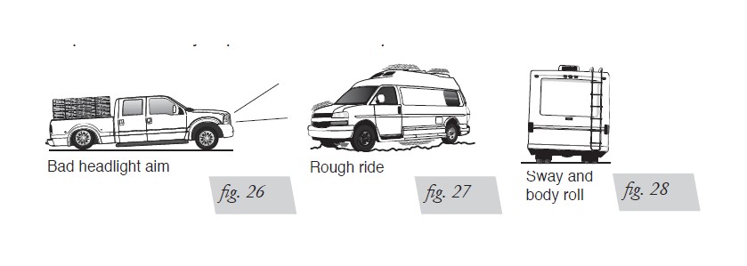
1. Level vehicle
If the vehicle’s headlights are shining into the trees or the vehicle is leaning to one side, then it is not level (Fig. 39). Raise the air pressure to correct either of these problems and level the vehicle.
2. Ride comfort
If the vehicle has a rough or harsh ride it may be due to either too much pressure or not enough (Fig. 40). Try different pressures to determine the best ride comfort.
3. Stability
Stability translates into safety and should be the priority, meaning the driver may need to sacrifice a perfectly level and comfortable ride. Stability issues include roll control, bounce, dive during braking and sponginess (Fig. 41). Tuning out these problems usually requires an increase in pressure.
GUIDELINES FOR ADDING AIR
1. Start with the vehicle level or slightly above.
2. When in doubt, always add air.
3. If the front of the vehicle dives while braking, increase the pressure in the front air bags, if equipped.
4. If it is ever suspected that the air bags have bottomed out, increase the pressure (Fig. 42).
5. Adjust the pressure up and down to find the best ride.
6. If the vehicle rocks and rolls, adjust the air pressure to reduce movement.
7. It may be necessary to maintain different pressures on each side of the vehicle.
Loads such as water, fuel, and appliances will cause the vehicle to be heavier on one
side (Fig. 43). As much as a 50 PSI difference is not uncommon.