FREE 1 to 3-Day Delivery on Orders $149+ Details
How to Install Air Lift Performance RideControl (02-08 RAM 1500) on your Dodge RAM
Installation Time
2 hours
Tools Required
- 7/16”, 9/16” open-end or box wrenches
- Crescent Wrench
- Ratchet with 3/8”, 9/16”, and 1/2” deep well sockets
- 3/8” and 5/16” drill bits (very sharp)
- 3/8” Nut Driver
- Heavy Duty Drill
- Torque Wrench
- Hose Cutter, Razor Blade, or Sharp Knife
- Hoist or Floor Jacks
- Safety Stands
- Safety Glasses
- Air Compressor, or Compressed Air Source
- Spray Bottle with Dish Soap/Water Solution
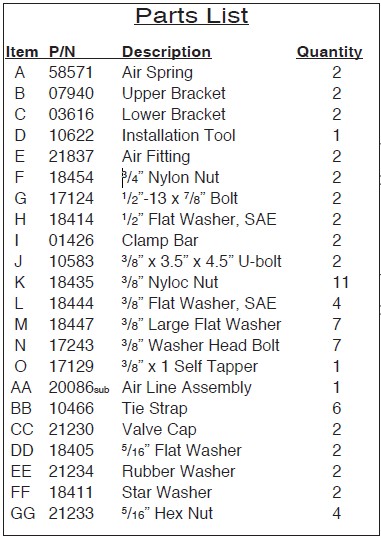
IMPORTANT: This kits mounts behind the axle. Figure 1 shows the installation for the driver side only. Refer to Figure 7 for the passenger side installation.
IMPORTANT: Your vehicle may be equipped with a rear brake proportioning valve. Any type of load assist product could affect brake performance. We recommend that you check with your dealer before installing this type of product. If your vehicle DOES NOT have a rear brake proportioning valve or is equipped with an anti-lock type brake system, installation of a load assist product will have NO EFFECT ON BRAKE SYSTEM PERFORMANCE.
I. Getting Started
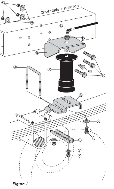
1. Determine the Normal Ride Height. The Normal Ride Height is the distance between the bottom edge of the wheel-well and the center of the hub with the vehicle in the “as delivered” condition. In some cases, Normal Ride Height is not perfectly level.
a. Remove unusual loads and examine your vehicle from the side to ensure it is on a level surface.
b. If necessary (in cases where your leaf springs are sagging badly), use a jack to raise the rear end so that the vehicle achieves the original “as delivered” ride height.
2. Measure the distance between the center of the hub and the bottom edge of the wheel well (Figure 2). This is the Normal Ride Height. Enter the measurement below:
NORMAL
RIDE HEIGHT: __________ inches
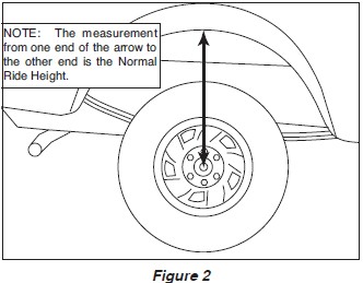
3. Measure the distance between the frame and the tire. This kit requires a minimum of 6” of clearance for a fully inflated air spring (Figure 3).
II. Raising the Vehicle
1. Raise the vehicle and remove the wheels.
2. Check the distance between the center of the hub and the bottom edge of the wheel to ensure that it is at the normal ride height recorded above. If not, raise the frame or lower the axle as necessary to restore the original distance.
a. If the vehicle is raised with an axle contact hoist, place axle stands under the frame and lower the axle as needed.
b. If the vehicle is raised with a frame contact hoist, place axle stands under the axle and lower the frame as needed.
c. If the vehicle is raised with a jack and supported with axle stands on the frame, use a floor jack to lower the axle.
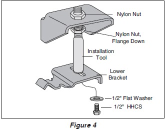
III. Assembling the Installation Tool
1. The tool provided with this kit will assist in proper setup and alignment of the air spring and will also position the upper bracket for drilling the bolt holes. The tool attaches to the upper and lower bracket and is rigid so that it will self-align the upper bracket. The threaded section of the upper part of the tool ensures that the air spring can only be mounted at the correct height. The air spring will work throughout the entire threaded range on the tool. This kit will mount behind the axle.
2. Secure the upper bracket (B) to the installation tool (D) using the provided nylon nut (F) (Figure 4).
3. Loosely attach the tool to the lower bracket (C) using 1/2” flat washer (H) and 1/2” bolt (G). Refer to Figure 4. Leave loose for adjustment.
IV. Attaching the Lower Bracket
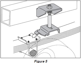
1. Set the assembly on the leaf spring behind the axle.
2. With the hook end of the lower bracket placed over the edge of the spring retaining plate (Figure 5), secure the lower bracket to the leaf spring with the provided U-bolt (J), clamp bar (I), flat washers (L), and lock nuts (K). Torque to 16 ft-lbs. NOTE: The bracket will pull down flat to the leaf spring when the lock nuts are tightened.
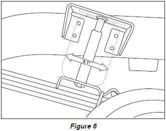
3. The air spring will expand to 5.1” in diameter at maximum inflation pressure. Check horizontally along the shaft of the installation tool for sufficient clearance of 2.50” all around the tool (Figure 6).
V. Positioning the Upper Bracket
1. Using the slot in the lower bracket, push the upper bracket against the frame rail.
2. Use the two nylon nuts on the threaded portion of the tool to adjust the upper bracket so that the legs are flat against the frame rail and all four holes are in the middle section of the frame. The mounting holes must not fall on the rounded edges of the frame rail and at least 1.5” must be left above the top of the upper bracket for air fitting clearance.
VI. Attaching the Upper Bracket
IMPORTANT: Please read this entire section completely before drilling any holes.
1. CAUTION: Before drilling, check the back side of the frame for clearance issues such as, brake lines, gas lines, electrical lines, etc. All obstacles need to be temporarily relocated to clear the area.
2. DRIVER SIDE INSTALLATION:
a. Center punch the lower rear hole and drill a 3/8” hole through the frame.
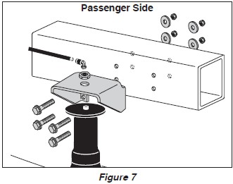
b. Loosely install a 3/8” washer head bolt (N), a large flat washer (M), and nylock nut (K). Figure 7 Passenger Side
c. Center punch the forward lower hole and drill a 3/8” hole through the frame.
d. Remove the tool by removing the bolt securing the tool to the lower bracket. Swing the bracket up and remove the nylon nut on the top of the upper bracket. Remove the tool. Save the hardware, as it will be reused to mount the air spring.
e. Replace the upper bracket to the mounting location and secure at the forward, lower mounting hole location using 3/8” washer head bolt (N), large flat washer (M) and nylock nut (K) as shown in Figure 1.
f. Center punch and drill a 5/16” hole for the forward upper hole and install a 3/8” self tapper (O). Tighten to 16 ft-lbs (Figure 1).
g. Drill the remaining hole out to a 3/8” diameter and install a 3/8” washer head bolt (N), a large flat washer (M), and a nyloc nut (K).
3. PASSENGER SIDE INSTALLATION: Install the passenger side assembly in the same manner, with the exception to the forward upper hole location. Drill this hole to a 3/8” diameter and install a 3/8” washer head bolt (N), a large flat washer (M), and a nyloc nut (K). No self tapper is used on the passenger side. Refer to Figure 7.
VII. Installing the Air Spring
1. Install 90 degree air swivel fitting (E) to the top of the air spring (A) (Figure 1). Use a 7/16” open end wrench being careful to tighten on the metal hex nut only. Tighten 1 1/2 turns. Do not over tighten. NOTE: This fitting is precoated with sealant.
2. Guide the fitting through the center mounting hole in the upper bracket (Figure 1).
3. Attach the air spring to the lower bracket using flat washer (H) and bolt (G). Carefully hand turn the air spring onto the lower mounting bolt. Leave loose for later adjustment.
4. Loosely, install nylon nut (F) over the air fitting and onto the upper threadpost of the air spring (Figure 1).
VIII. Aligning the Air Spring
1. IMPORTANT: With the bottom and top of the air spring still loose, inflate the air spring to approximately 10 p.s.i.
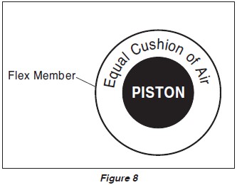
2. Use the slotted adjustment in the lower bracket to correctly align the air spring between the upper and lower brackets. This can be accomplished by lightly tapping it inboard or outboard for proper alignment. There should be a symmetrical cushion of air around the base of the air spring when correctly positioned (Figure 8).
3. Tighten the lower mounting bolt with a 3/4” wrench. Hand tight is sufficient. Do not attempt to hold the air spring with any type of tool.
4. Tighten the nylon nut to 4 ft-lbs.
5. Repeat entire installation procedure for other side.
IX. Installing the Air Lines
1. Choose a convenient location for mounting the inflation valves. Popular locations for the inflation valve are: the wheel well flanges, the license plate recess in bumper, under the gas cap access door, or through license plate itself. NOTE: What ever the chosen location is, make sure there is enough clearance around the inflation valves for an air chuck. Equal Cushion of Air PISTON Flex Member
2. Drill a 5/16 “ hole to install the inflation valves.
3. Cut the air line assembly (AA) in two equal lengths. CAUTION: When cutting or trimming the air line, use a hose cutter, a razor blade or a sharp knife. A clean, square cut will ensure against leaks. Do not use wire cutters or scissors to cut the air line. These tools may flatten or crimp the air line, causing it to leak around the O-ring seal inside the elbow fitting.
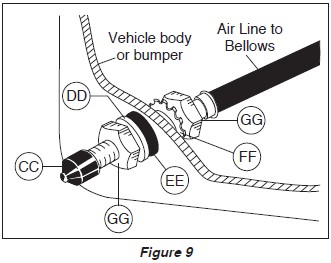
4. Place a 5/16 “ nut (GG) and a star washer (FF) on the air valve. Leave enough of the inflation valve in front of the nut to extend through the hole and have room for the rubber washer (EE), flat washer (DD), and 5/16 “ nut (GG) and cap (CC). There should be enough valve exposed after installation - approximately 1/2 “ - to easily apply a pressure gauge or an air chuck (Figure 9).
5. Push the inflation valve through the hole and use the rubber washer (EE), flat washer (DD), and another 5/16 “ nut (GG) to secure it in place. Tighten the nuts to secure the assembly in place (Figure 9).
6. Route the air line along the frame to the air fitting on the air spring. Keep at least 6” of clearance between the air line and heat sources, such as the exhaust pipes, muffler, or catalytic converter. Avoid sharp bends and edges. Use the plastic tie straps (BB) to secure the air line to fixed, non-moving points along the chassis. Be sure that the tie straps are tight, but do not pinch the air line. Leave at least 2” of slack to allow for any movement that might pull on the air line.
7. Cut off air line leaving approximately 12” of extra air line. A clean square cut will ensure against leaks. Insert the air line into the air fitting. This is a push to connect fitting. Simply push the air line into the 90° swivel fitting until it bottoms out (9/16” of air line should be in the fitting).
8. Install the minimum/maximum air pressure decal in a highly visible location. We suggest placing it on the driver’s side window just above the door handle.
X. Checking for Leaks
1. Inflate the air spring to 30 p.s.i.
2. Spray all connections and the inflation valves with a solution of 1/5 liquid dish soap and 4/5 water to check for leaks. You should be able to spot leaks easily by looking for bubbles in the soapy water.
3. After the test, deflate the springs to the minimum pressure required to restore the Normal Ride Height, but not less than 5 p.s.i.
4. IMPORTANT: Check the air pressure again after 24 hours. A 2 to 4 p.s.i. loss after initial installation is normal. Retest for leaks if the loss is more than 5 lbs.
XI. Fixing Leaks
1. If there is a problem with the swivel fitting, then:
a. Check the air line connection by deflating the spring and removing the line by pulling the collar against the fitting and pulling firmly on the air line. Trim 1” off the end of the air line. Be sure the cut is clean and square. Reinsert the air line into the push-to-connect fitting.
b. Check the threaded connection by tightening the swivel fitting another 1/2 turn. If it still leaks, deflate the air spring, remove the fitting, and re-coat the threads with thread sealant. Reinstall by hand tightening as much as possible, then use a wrench for an additional two turns.
2. If there is a problem with the inflation valve, then:
a. Check the valve core by tightening it with a valve core tool.
b. Check the air line connection by removing the air line from the barbed type fitting. CAUTION: Do not cut it off. As this will usually nick the barb and render the fitting useless. Cut air line off a few inches in front of the fitting and use a pair of pliers or vise-grips to pull/twist the air line off the fitting.
3. If the preceding steps have not resolved the problem, call Air Lift Technical Service at 1-800-248-0892 for assistance.
XII. Troubleshooting Guide
Problems maintaining air pressure, without on-board compressor.
1. Leak test the air line connections and threaded connection of the elbow into the air spring. See Section XI to repair.
2. Leak test the inflation valve for leaks at the air line connection or dirt or debris in the valve core. See Section XI to repair.
3. Inspect air lines to be sure it is not pinched. Tie straps may be too tight. Loosen or replace strap. Replace leaking components.
4. Inspect air line for holes and cracks. Replace as needed.
5. A kink or fold in the air line. Reroute as needed.
XIII. Checklist
You can protect your warranty on this product and prevent unnecessary wear by ensuring the following checks have been made:
Section I – Installation (To be completed by the installer):
1. Clearance Test - Inflate the air springs to 60 p.s.i. and ensure there is at least 1/2 “ clearance around each sleeve from anything that might rub against them. Be sure to check the tire, brake drum, frame, shock absorbers and brake cables.
2. Leak Test Before Road Test – Inflate the air springs to 60 p.s.i., check all connections for leaks with a soapy water solution. See page 6 of the manual for tips on how to spot leaks. All leaks must be eliminated before the vehicle is road tested.
3. Heat Test – Be sure there is sufficient clearance from heat sources - at least 6” for air springs and air lines. If a heat shield was included in the kit - install it. If there is no heat shield, but one is required, call 1-800-248-0892.
4. Fastener Test – Recheck all bolts for proper torque.
Torque Guide:
3/8 “ Frame Bolts 16 ft-lbs
U-bolt Lock Nuts 16 ft-lbs
5. Road Test – The vehicle should be road tested after the preceding tests. Inflate the springs to 25 p.s.i. (50 p.s.i. if vehicle is loaded). Drive the vehicle 10 miles and recheck for clearance, loose fasteners and/or air leaks.
6. Operating Instructions – If professionally installed, the installer should review the operating instructions on page 8 with the owner. Be sure to provide the owner with all of the paperwork that came with the kit.
Section II - Post Installation Checklist (To be completed by the owner):
1. Overnight Leakdown Test – Recheck air pressure after vehicle has been used for 24 hours. If pressure has dropped more than 5 p.s.i. then, you have a leak that must be fixed. Either fix the leak yourself (see page 6) or return to the installer for service.
2. Air Pressure Requirements – I understand that the air pressure requirements of my air spring system are as follows:
Minimum ___________ Maximum ___________
I also understand that I must inflate the air springs until the Ride Height measurement that was recorded on page 2 has been restored. Regardless of load, the air pressure should always be adjusted so that the Ride Height is maintained at all times.
3. Thirty Day or 500 Mile Test. I understand that I must recheck the air spring system after 30 days or 500 miles, whichever comes first. If any part shows signs of rubbing or abrasion, the source should be identified and moved, if possible. If it is not possible to relocate the cause of the abrasion, the air spring may need to be remounted. If professionally installed, the installer should be consulted. Check all fasteners for
tightness.
XIV. Maintenance and Operations
By following these steps, vehicle owners will obtain the longest life and best results from their air springs.
1. Check the air pressure weekly.
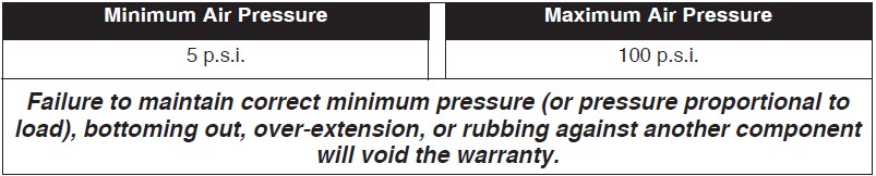
2. Always maintain Normal Ride Height. Never inflate beyond 100 p.s.i.
3. If you develop an air leak in the system, use a soapy water solution to check all air line connections and the inflation valve core before deflating and removing the air spring (see page 6).
4. When increasing load, always adjust the air pressure to maintain the Normal Ride Height. Increase or decrease pressure from the system as necessary to attain Normal Ride Height for optimal ride and handling. Remember that loads carried behind the axle (including tongue loads) require more leveling force (pressure) than those carried directly over the axle.
5. IMPORTANT: For your safety and to prevent possible damage to your vehicle, do not exceed maximum Gross Vehicle Weight Rating (GVWR), as indicated by the vehicle manufacturer. Although your air springs are rated at a maximum inflation pressure of 100 p.s.i. The air pressure actually needed is dependant on your load and GVWR, which may be less than 100 p.s.i. Check your vehicle owners manual and do not exceed the maximum load listed for your vehicle.
6. Always add air to springs in small quantities, checking the pressure frequently. Sleeves require less air volume than a tire and inflate quickly.
7. Should it become necessary to raise the vehicle by the frame, make sure the system is at minimum pressure (5 p.s.i.) to reduce the tension on the suspension/brake components. Use of on–board leveling systems do not require deflation or disconnection.