FREE 1 to 3-Day Delivery on Orders $149+ Details
How to Install Air Lift Performance AirCell Non-Adjustable Load Support - Rear (07-18 Silverado 1500) on your Chevy Silverado
Installation Time
1 hours
Tools Required
- Hoist or floor jacks
- Safety stands
- Metric sockets
- Metric wrenches
- Ratchet
Installation Diagrams
Important Safety Notice
The installation of this kit does not alter the Gross Vehicle Weight Rating (GVWR) or payload of the vehicle. Check your vehicle’s owner’s manual and do not exceed the maximum load listed for your vehicle.
Gross Vehicle Weight Rating: The maximum allowable weight of the fully loaded vehicle (including passengers and cargo). This number — along with other weight limits, as well as tire, rim size and inflation pressure data — is shown on the vehicle’s Safety Compliance Certification Label.
Payload: The combined, maximum allowable weight of cargo and pasengers that the truck is designed to carry. Payload is GVWR minus the Base Curb Weight.
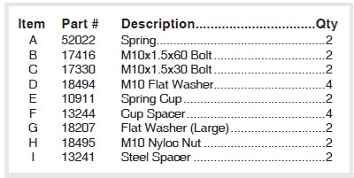
HARDWARE LIST
Installing the AirCell System
ASSEMBLING AND ATTACHING THE SYSTEM
1. Jack up the rear of the vehicle or raise on a hoist. Support the frame with safety stands. Lower the axle of the vehicle until the suspension is fully extended.
2. Remove the existing jounce bumper assembly on both sides.
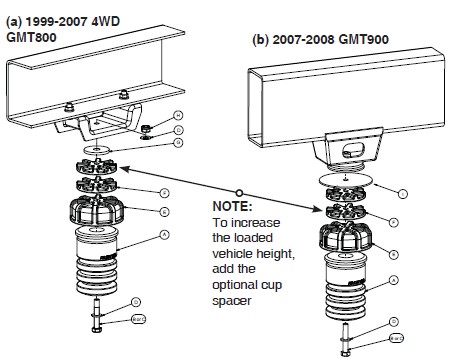
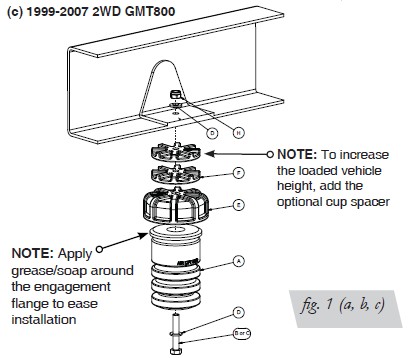
3. For 2WD GMT800 and all GMT900 Models, using the existing frame hole that the stock jounce bumper was removed from, attach the spring cup and the bracket to the frame using the supplied M10 bolt, flat washers (use lock nut for the GMT800 only) (and the large steel spacer for the GMT900) (fig 1b & c). Torque the mounting hardware to 37ft/lbs.
4. For the 4WD GMT800 attach the spring cup to the existing jounce bumper bracket using an M10 bolt, flat washer through the spring cup, spring cup spacer, large flat washer, through the stock bracket and capped with a flat washer and nyloc nut (fig 1a). Torque the mounting hardware to 37ft/lbs.
5. Insert the spring into the cup. A twisting while pushing the spring into the cup will make the installation quicker. Make sure the spring snaps into position into the cup.
NOTE: Applying grease or soap around the engagement flange of the spring (A) will help in aiding the spring (A) to “snap” into the spring cup (E).
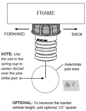
6. Do a quick check of the alignment. If needed, remove the spring and re-position the cup by using the slot for adjustment (fig 2). once positioned correctly, re-torque the hardware and repeat spring installation if previously removed.
OPTIONAL: You can adjust the loaded height of the vehicle by adding the optional cup spacer between the cup and the bracket. It will be necessary to use the longer hardware provided to install the cup spacer (see fig 1 note).