 FREE 1 to 3-Day Delivery on Orders $149+ Details
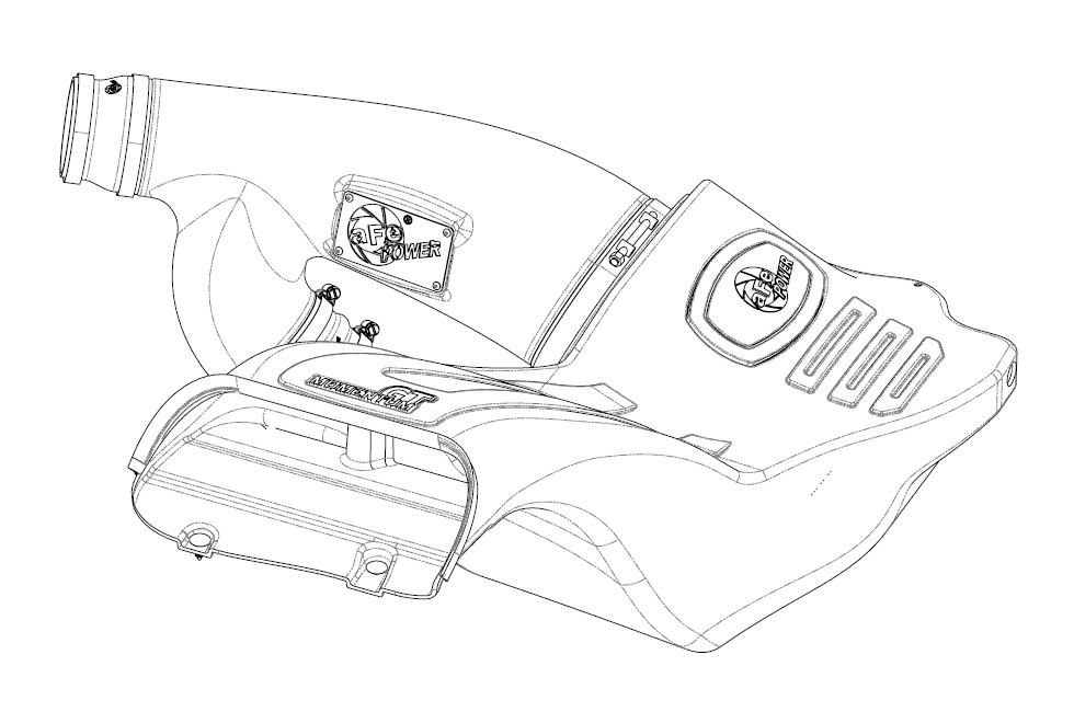
How to Install AFE Momentum GT Guard 7 Cold Air Intake (2017 Raptor) on your Ford F-150
Installation Time
1 hours
Tools Required
- 7mm/8mm/11mm nut driver or deep sockets
- flat head screw driver
- 13mm socket and driver
- panel popper tool
• Please read the entire instruction manual before proceeding.
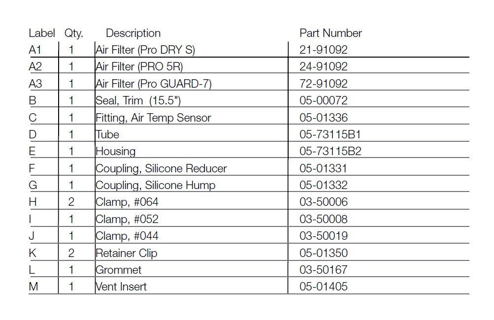
• Ensure all components listed are present.
• If you are missing any of the components, call customer support at 951-493-7100.
• Ensure you have all necessary tools before proceeding.
• Do not attempt to work on your vehicle when the engine is hot.
• Disconnect the negative battery terminal before proceeding.
• Retain factory parts for future use.
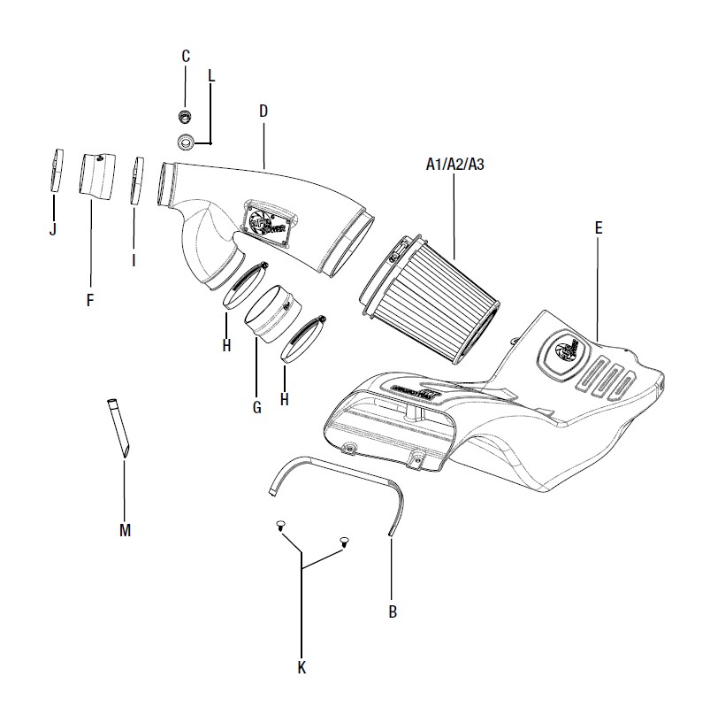
Refer to Figure A for Steps 1-2
Step 1: Unplug temp sensor harness 1 from the back side of the intake tube. Unclip the coolant line from the intake tube.
Step 2: Loosen the clamps 2 on the intake tubes. Unclip the top of the air box 3 and remove the tube, air filter and top of the air box from the vehicle.
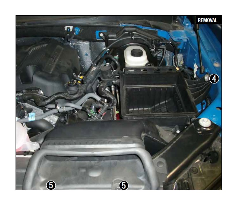
Refer to Figure B for Steps 3-5
Step 3: Unclip the wire from the back of the air box.
Step 4: Remove the wastegate accuator from the housing.
Step 5: Remove the screw 4 and the two plastic rivets 5 securing the housing, then pull the factory air box out of the truck.
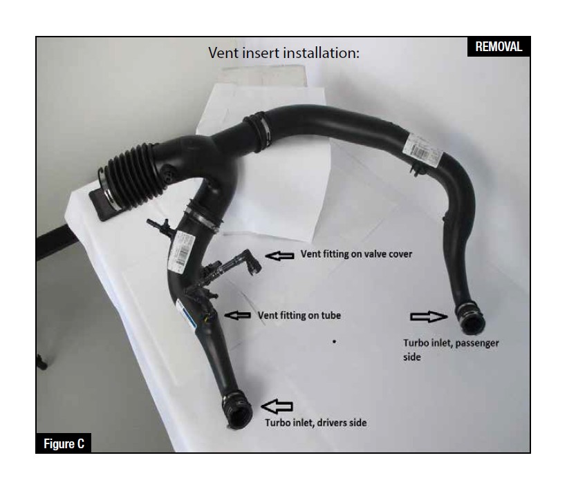
Refer to Figure C for Step 6
(These procedures should be done with the inlet tubes installed on the engine. It is shown off the vehicle for better illustration.)
Step 6: Locate the o.e. plastic tube feeding the driver’s side turbo inlet.
Refer to Figure I for Step 7
Step 7: Locate the valve cover vent tube that feeds into driver’s side turbo inlet. It is not necessary to remove the engine cover.
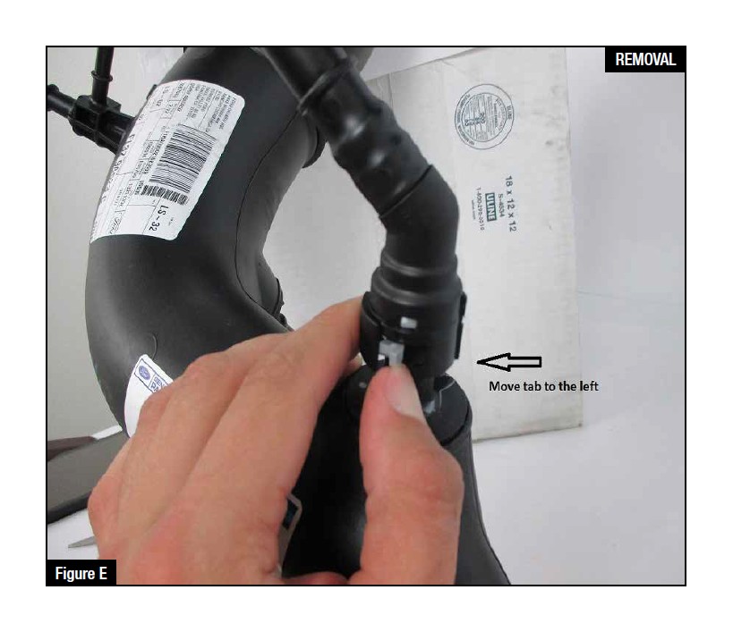
Refer to Figure E for Step 8
Step 8: Note the release clip on the vent tube connectors. Apply pressure against the exposed tail and pull vent fitting off of the turbo inlet tube. It is not necessary to disconnect at the valve cover end. There is a sensor and wire harness on this vent tube. Do not damage or remove these components.
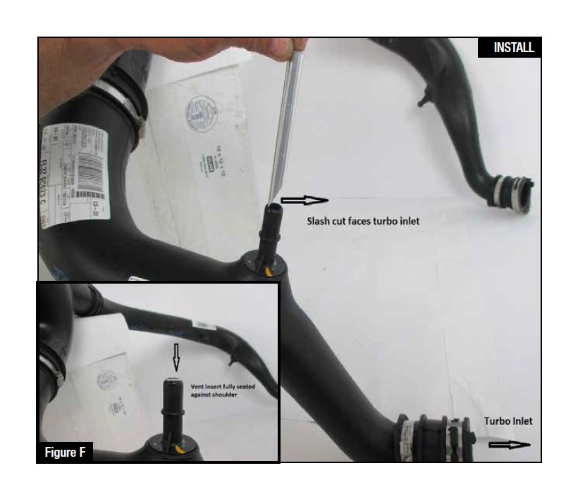
Refer to Figure F for Step 9
Step 9: Insert vent fitting with slash cut facing turbo inlet. It should not be a loose fit. It is direction dependent and must not rotate once installed.
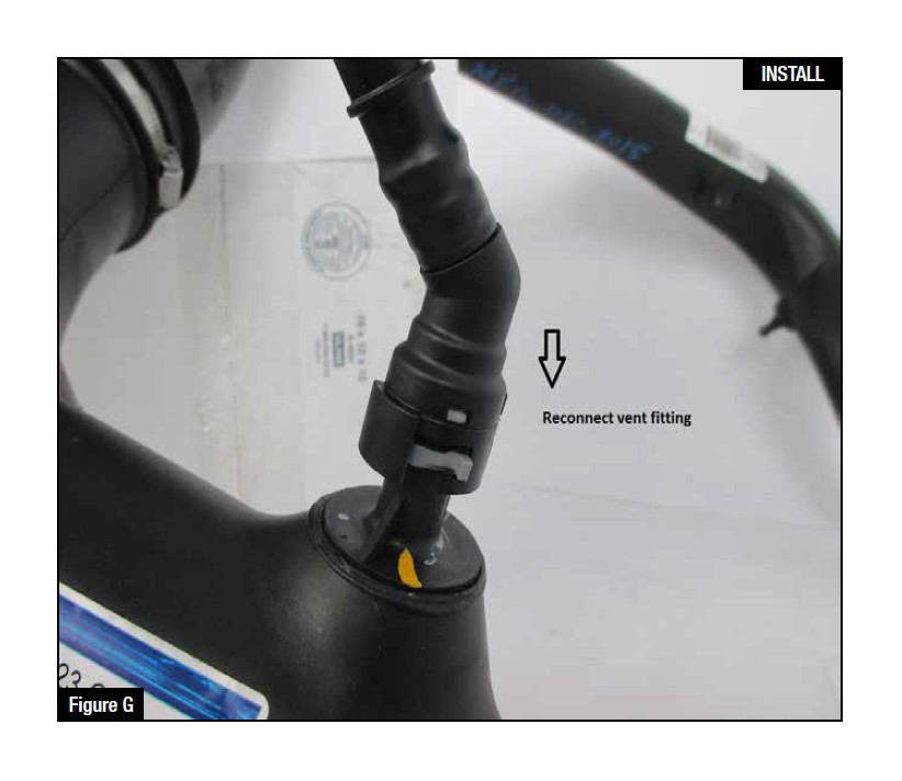
Refer to Figure G for Steps 10-11
Step 10: Reconnect the vent fitting. It will snap over without having to release the plastic clip. Pull up slightly to confirm installation.
Step 11: Installation is complete. Any codes can be cleared with a code reader or by disconnecting the battery. You will lose any radio presets with battery disconnection.
If removal of the vent insert is required, it can be pulled out with internal snap ring pliers.
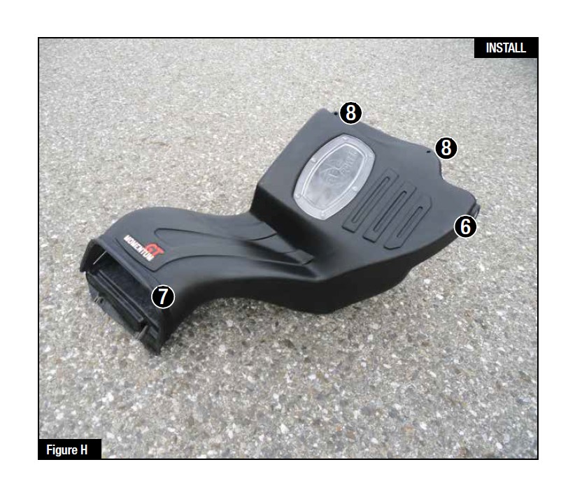
Refer to Figure H for Steps 12-13
Step 12: Transfer the grommet 6 from the factory air box to the aFe air box.
Step 13: Install the furnished seal trim 7 on the top edge of the aFe housing.
Optional: Drill two small holes in the top of the housing for the wastegate accutator wire harness to clip into. There are two drill points marking these locations and the hole size is 1/4". 8 This will allow you to mount the wastegate actuator wire to the air box, however, it will require you to relocate the push clips on the factory wire.
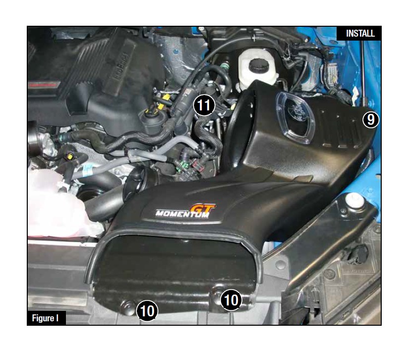
Refer to Figure I for Steps 14-17
Step 14: Install the aFe housing into the truck by pushing it into the factory mounting grommets.
Step 15: Re-install the factory screw 9 removed in Step 5, inside the aFe housing.
Step 16: Secure the housing with the two furnished plastic rivets 10 .
Step 17: Reconnect the wastegate accutator to the bracket on the back side of the housing. 11
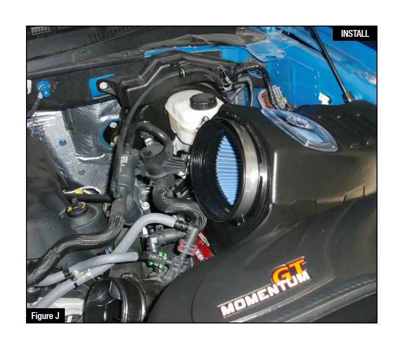
Refer to Figure J for Step 18
Step 18: Slide aFe filter inside the housing and push it in until it locks.
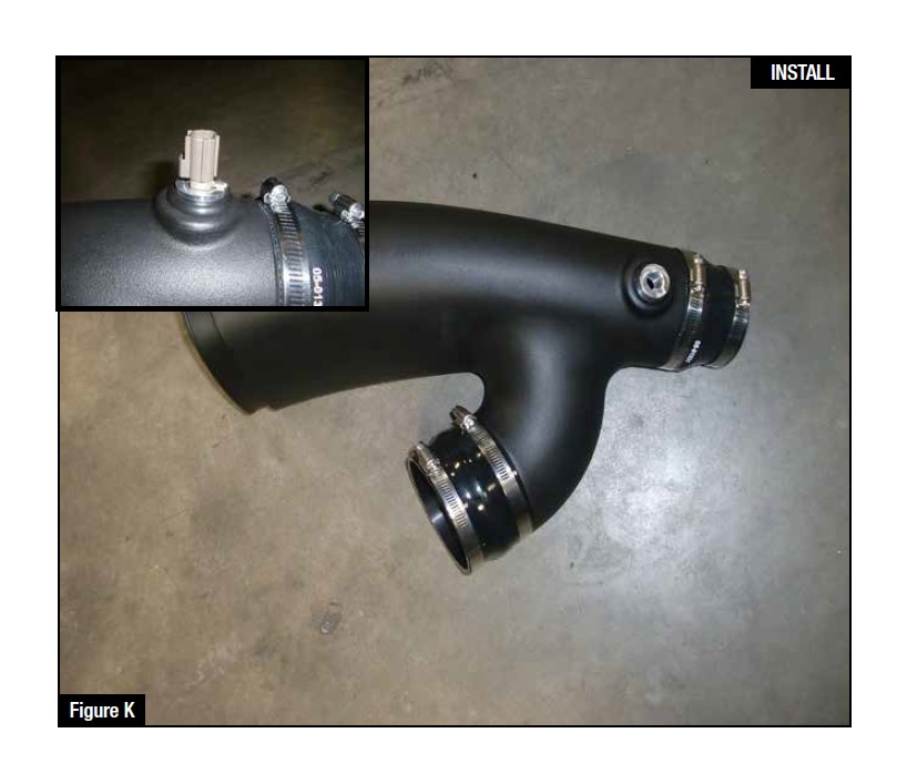
Refer to Figure K for Steps 19-21
Step 19: Install grommet into hole in aFe tube then push the aluminum fitting in it.
Step 20: Install couplings and clamps onto tube ends. Do not tighten clamps yet.
Step 21: Transfer the temperature sensor from the factory intake tube to the new aFe intake tube.
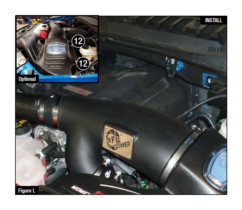
Refer to Figure L for Steps 22-24
Step 22: Install the aFe tube in the truck by sliding the couplings over the factory tube then the tube end into aFe filter.
Step 23: Align tube correctly then tighten all clamps.
Step 24: Reconnect the temp sensor harness.
Optional: Locate the two plastic push clips for the wastegate actuator harness. Cut the tape securing these to the wire. Place the push clip in the drilled holes on the housing. Hold the wire in place along side these push clips and retape the push clips in the appropiate locations on the wire 12 .
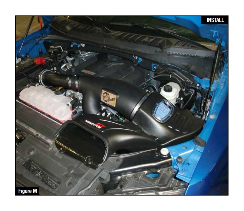
Refer to Figure M for Step 25
Step 25: Make sure all clamps and screws are tight. Remove plastic film from aFe window. Your installation is now complete.
NOTE: Check all bolts, clamps, and connectors after 200 miles.

