 FREE 1 to 3-Day Delivery on Orders $149+ Details
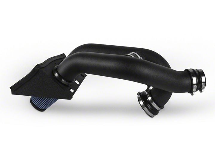
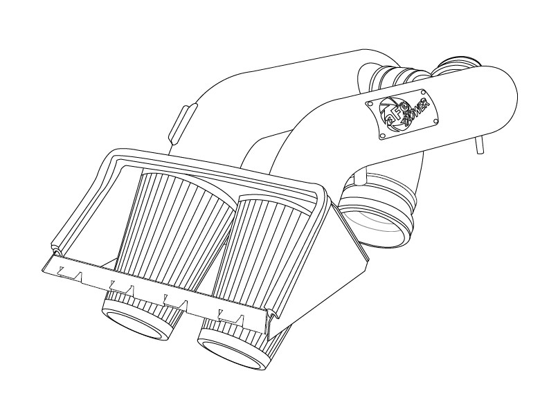
How to Install AFE Magnum Force Stage 2 Pro Dry S Cold Air Intake - Black (12-14 3.5L EcoBoost) on your Ford F-150
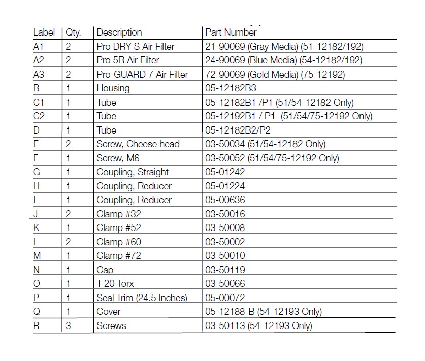
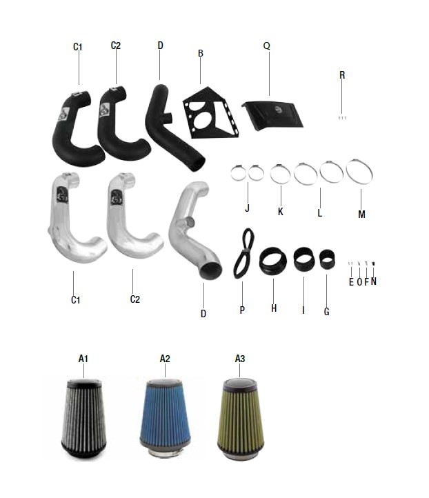
Shop Parts in this Guide
• Please read the entire instruction manual before proceeding.
• Ensure all components listed are present.
• If you are missing any of the components, call customer support at 951-493-7100.
• Ensure you have all necessary tools before proceeding.
• Do not attempt to work on your vehicle when the engine is hot.
• Disconnect the negative battery terminal before proceeding.
NOTE: Retain factory parts for future use.
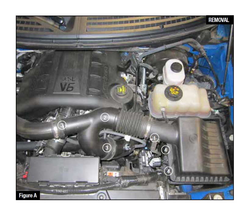
Refer to Figure A for steps 1-5
Step 1: Disconnect the Manifold Air Pressure (MAP) sensor plug from stock air box. 1
Step 2: For 51/54-12182 only unplug the vacuum line from the underside of the OE intake tube. 2
Step 3: Loosen the OE intake clamps using an 8mm nut driver from the left and right side runners. 3
Step 4: Uncalmp the top portion of the OE air box. 4
Step 5: Remove the OE intake and the top portion of the OE air box by pulling straight up and out of the vehicle.
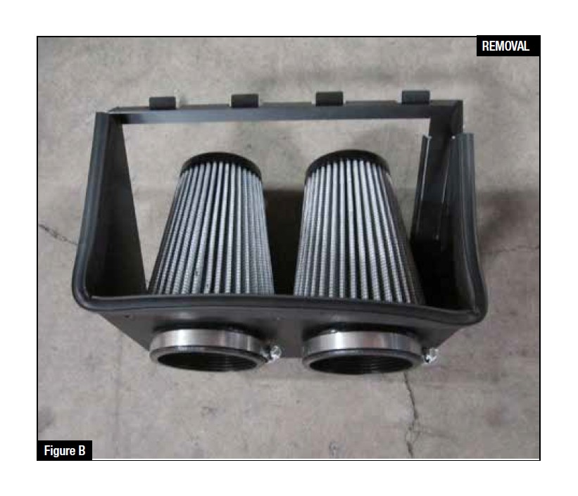
Refer to Figure B for steps 6-8
Step 6: Pre-assemble the aFe housing; insert both aFe filters through the housing.
Step 7: Pre-assemble the filter clamps but do not tighten.
Step 8: Install the seal trim around the edges of the housing.
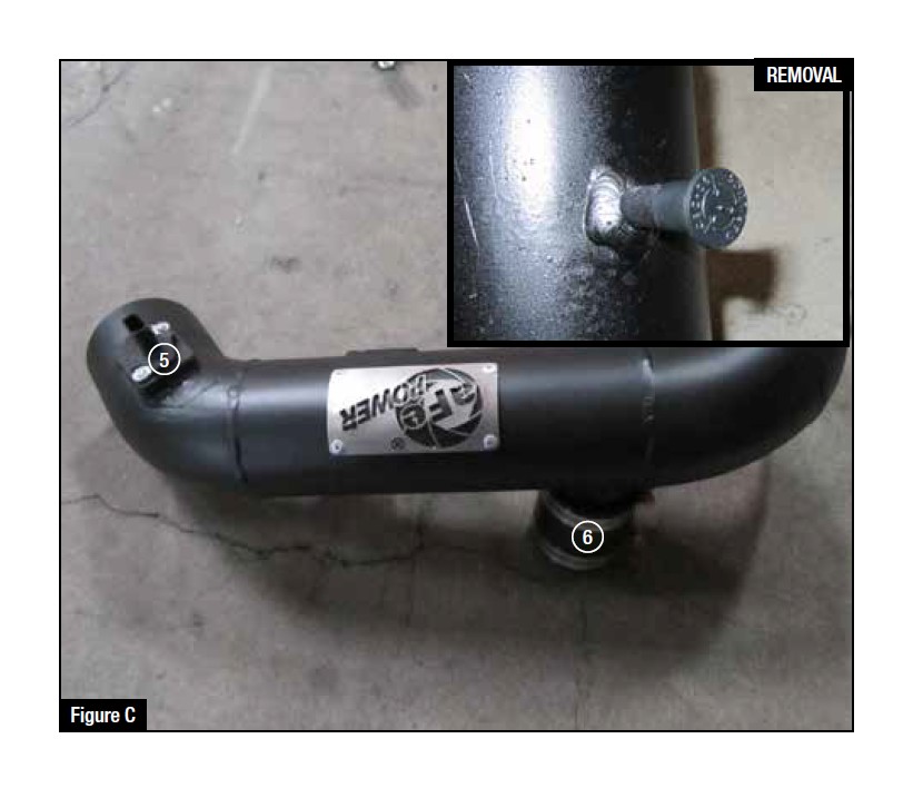
Refer to Figure C for steps 9-11
Step 9: Remove the MAP sensor from the OE intake using the provided T-20 torx bit.
Step 10: Install the MAP sensor on the front aFe intake tube using the provided hardware. 5
Step 11: Install the small straight coupling on the cross over tube, install clamps but do not tighten. 6
For 51/54/75-12192 install the 3/8" vent plug on the rear tube.
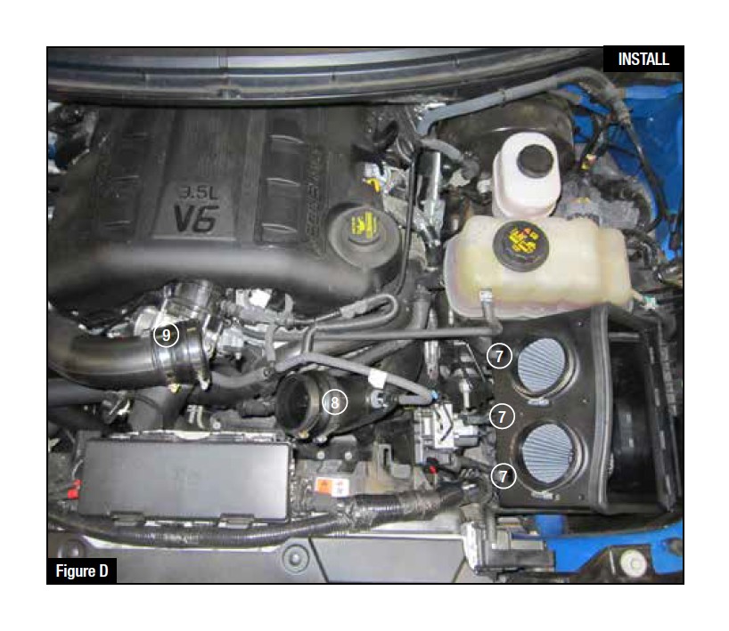
Refer to Figure D for steps 12-14
Step 12: Install the aFe housing on top of the lower portion of the OE housing. Clamp down using factory air box clips. 7
Step 13: Install the larger reduction coupling (05-00612) on the driver side runner. Clamp down but do not tighten. 8
Step 14: Install the smaller reduction coupling (05-00636) on the passenger side runner. Clamp down but do not tighten. 9
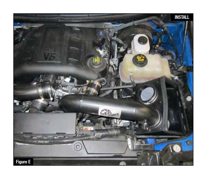
Refer to Figure E for step 15
Step 15: Install the front aFe intake tube with the MAP sensor. (Slide into coupler side before installing the filter side). Do not tighten clamps.
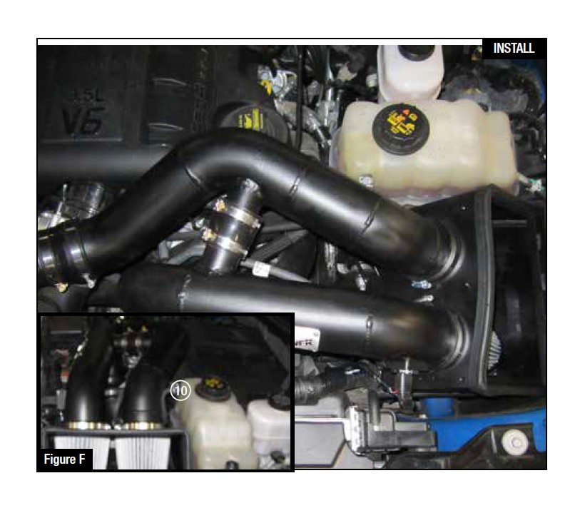
Refer to Figure F for steps 16-18
Step 16: Install the rear aFe intake tube. (First install into coupler side before installing the filter side). Do not tighten clamps.
Step 17: Slide the small straight coupling from the front aFe intake tube to the rear cross over tube.
Step 18: Adjust both intake tubes if needed then tighten down all clamps with an 8mm nut driver.
Note: If there is contact with the coolant reservoir vent hose, this hose can be trimmed 1/4" for extra clearance. Reconnect after trimming. 10
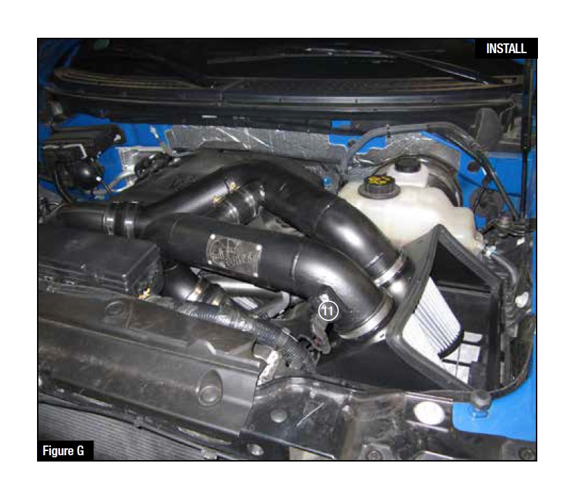
Refer to Figure G for steps 19-20
Step 19: For 51/54/12182 reconnect the vacuum line to the rear aFe intake tube.
Step 20: Reconnect the MAP sensor harness. 11

