FREE 1 to 3-Day Delivery on Orders $149+ Details
How to Install AEM Electronics Tru-Boost Controller Gauge - Electrical (07-17 Silverado 1500) on your Chevy Silverado
AEM’s Tru Boost boost controller gauge is a stand-alone boost controller that features a
th ree digit LED digital readout with 24 sweeping multi color LED’s, two programming
buttons, and an on-board pressure sensor. The Tru Boost kit contains all necessary
components, including an AEM high performance boost control solenoid, to install and
use the Tru Boost.
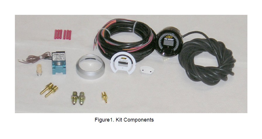
Contents: See Figure 1.
(1) Tru Boost Ga uge assembly
(1) Appearance kit (Silver bezel, silver pin guide, white faceplate)
(1) Installation kit (Butt connector, 6 pieces)
(1) Tru Boost cable
(1) Boost solenoid
(1) Instruction manual
(1) Boost hose 10’
(1) 1/8” barb to 1/8” NPT fitting
(1) Sintered Muffler
(2) –6 to 1/8” NPT fitting
(2) 3/16” barb to 1/8” NPT fitting
Installing the Gauge
The AEM Tru Boost boost controller gauge requires a standard 2 1/16” (52MM)
mounting hole and can be mounted in a flat panel or most standard gauge pods. The
included cable contains two wire bundles and a 5-pin connector. The 5-pin connector
connects to a mating 5-pin connector on the back of the gauge. See Figure 2. Connect
the black and red wires in the long 2-wire bundle to the leads from the boost solenoid.
Polarity does not matter. Connect the black wire from the 5-wire bundle to a good
ground. Connect the 2 red wires to a fused, switched, 12Vdc power source. The gray
wire is an optional low side driver output. The orange wire is an optional scramble
boost input. The orange and gray wires do not need to be connected for the gauge to
function.
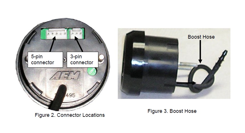
The boost hose protruding from the back of the gauge is connected to the on-board
p ressure sensor. See Figure 3. When using the on-board pressure sensor, the boost
hose must be connected to manifold pressure. Connect the boost hose to manifold
pressure using the supplied tubing and 1/8” NPT barb or an existing manifold pressu re
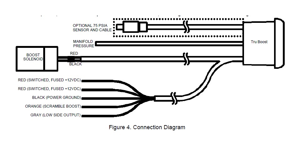
port. (NOTE: Do not pull on the boost hose) See Figure 4 for a connection diagram.
Scramble Boost Connection (Optional)
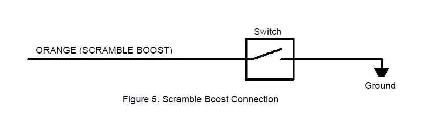
Scramble boost is activated when the orange wire is grounded. Connect the
orange wire to ground through a switch as shown in Figure 5.
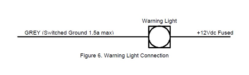
Warning Light Connection (Optional)
The Tru Boost will ground the gray wire when the alarm is activated. Connect
th e grey wire to a warni ng light as shown in Figure 6.
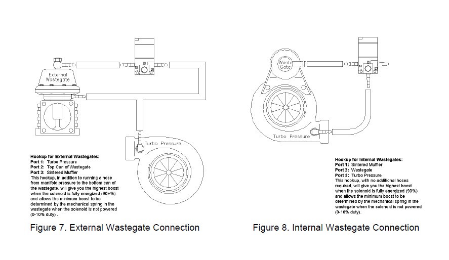
Boost Solenoid Connections
When energized, ports 1 & 2 are connected, when de-energized, ports 2 & 3 are
connected. The port numbers are clearly noted on the solenoid body. See Figures 7
and 8 for plumbing instructions.
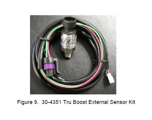
External Pressure Sensor
The Tru Boost is capa ble of reading boost levels up to 50 psig when using the
optional external sensor kit. The 30-4351 sensor kit comes with an AEM 75psia sensor
and a harness to connect the sensor to the Tru Boost. See Figure 9. Plug the single
row 3-pin connector into the mating connector on the back of the gauge. See Figure 2 .
Plug the black 3-pin connector into the pressure sensor. In order for the Tru Boost to
read the external sensor, the external sensor (E) must be selected in the pressure
sensor (SEn) option.
Configuring the Tru Boost
The Tru Boost has 9 u ser adjustable options. Descriptions of each option, along
with th e abbreviation and default value for each option shown in parenthesis, are listed
below:
Display Units: (UnI - PSI)
Use the buttons on th e front of the gauge to change the units displayed by the
gauge. Select from Psig (PSI), Bar (bAr), and Kpg (PAS).
Scramble Boost: (SCb - 10.0)
Set the scramble boost du ty cycle output. Duty cycle can be set between 10%
and 90%. The Tru Boost will output the selected duty cycle when the scramble boost
input is grounded.
Scramble Boost Time: (SCr - 0.00)
Select the duration of time (0-2 5.5 seconds) the Tru Boost will output the
scramble boost duty cycle when the scramble boost input is grounded.
Pressure Sensor: (SEn - I)
Select the pressure se nsor to be used by the Tru Boost. The internal sensor (I)
is used for boost levels up to 29 psig. The optional external sensor (E) is used for boost
levels above 29 psig, up to 50 psig.
Alarm: (ALA - 30)
Set the boost pressure at which the alarm will activate. When the alarm is
activated, the LED lights flash yellow and the warning light output (grey wire) is pu lled to ground.
Spring Pressure: (SPr – 2.00)
Enter the waste gate sprin g pressure(3psi less then your spring). The Tru Boost
will keep the boost solenoid open from 1 psi until boost exceeds the selected value.
This value can be adjusted to reduce lead in boost spikes or reduce spool up time. If
the spring pressure is unknown, a conservative starting value of 5 is suggested.
Bar Graph Full Scale: (FUL – 30)
Set the full-scale value of the sweeping LED lights. The LED lights start at 0 psig
and stop at the full-scale value, increasing in 24 equal increments.
Boost Setting A: (AXX – A10)
Set the output duty cycle (10%-90%) for setting A. For setting A, the duty cycle
is displayed as “AXX”. When setting duty cycle, the gauge will display the current
manifold pressure. When either button is pressed to increase or decrease duty cyc
the gauge will momentarily display the selected duty cycle before returning to manifold
pressure.
Boost Setting B: (bXX – b10)
Same as A, except duty cycle is displayed as “bXX”.
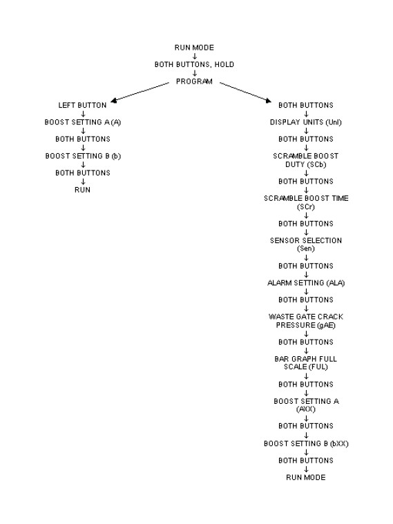
NOTE: While configuring the Tru Boost, the Tru Boost will stay in the programming mode until either the run mode is reached, or the power is turned off. Also, since the Tru Boost does not change run modes while in the programming menu, the corresponding run mode must be selected befo re entering the programming menu in order to view real time boost changes.
To enter the program menu, hold both buttons down for 2 seconds and release then th e gauge will display “PRG”. Hold both buttons again for 2 seconds and release to move to the first option. Push both buttons at the same time to move to the next option. The order of options is shown in the menu tree below. As a shortcut, the ga uge will skip to boost setting A if only the left button is pressed after “PRG” is displayed.
Using the Tru Boost
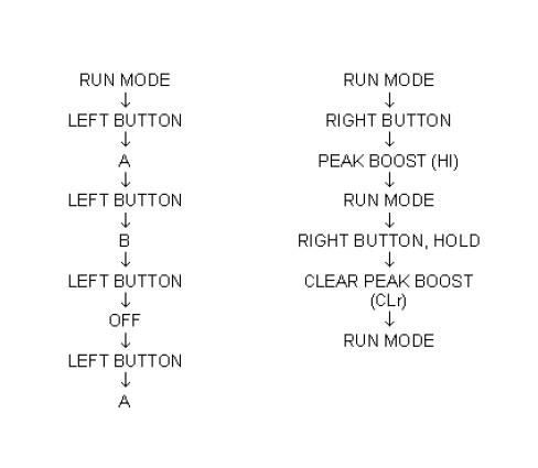
The Tru Boost has 3 running modes. In all modes, for manifold pressures less
than 0 psig, the sweeping LED’s remain off, the gauge displays pressure in units of
in-hg, and the displayed values are negative. In mode A, the gauge will output the duty
cycle selected for boost setting A. The gauge will output the duty cycle selected for
boost setting B when in mode B. In the “OFF” mode, the solenoid output is turned off.
Press and hold the left button for 2 seconds to change run modes. The order of run
modes is shown in the menu tree below. The gauge also remembers the peak boost
level achieved. Press and hold the right button for 2 seconds to display the peak boost.
Press and hold the right button for 4 seconds to clear the peak boost value.
Scramble Boost
Scramble boost is a feature that allows the driver to momentarily change the duty
cycle output of the Tru Boost. The output duty cycle for scramble boost is set in the
scramble boost (SCb) option. The scramble boost duration is set by the scramble boost
time (SCr) option. Scramble boost is activated by grounding the orange scramble boost
input wire.
Alarm
All 24 LED lights will flash yellow if manifold pressure exceeds the alarm level for
more than 1 second. The low side driver output will also switch to ground. The LED
lights will continue to flash and the output will stay grounded until either button is
pushed or the gauge is turned off.
Over-Boost
The boost solenoid will shut off and all 24 LED lights will flash red if manifold
pressure exceeds the alarm value by 10% for more than 1 second or if manifold
pressure exceeds the alarm level by 20% for more than 200 milliseconds. The solenoid
will remain off and the LED lights will continue to flash until either button is pushed or
the gauge is turned off.
Error Detection
ErP- If the external sensor is shorted or disconnected, the LED lights will flash
red and the center digits will display “ErP”. The error code will not activate when using
the internal pressure sensor.
ErS- If the boost solenoid is shorted or disconnected, the LED lights will flash red
and the center digits will display “ErS”. The error code will not activate when the Tru
Boost is on the off mode. Note: The solenoid always has a small pwm signal to allow
for fault detection.
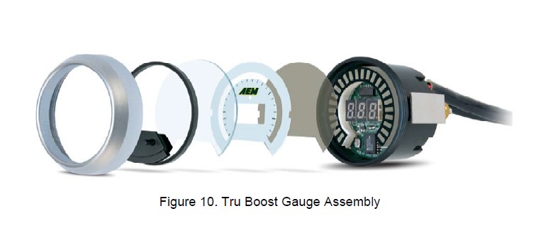
Changing the gauge configuration
The AEM Tru Boost comes configured with the black bezel, black pin guide, and
the black faceplate. However, a silver bezel, a silver pin guide, and a white faceplate
are also included in the gauge kit. To change the faceplate, pin guide, or bezel, orient
the gauge so you are looking at the faceplate. Rotate the bezel counter-clockwise to
unscrew it from the gauge cup. The bezel, lens, pin guide, rubber spacer, faceplate,
diffuser, and anti-glare shield are all removable. Reassemble the gauge as shown in
Figure 10. Make sure the small light holes in the faceplate, diffuser, and anti-glare
shield line up with the light sensor on the circuit board. Do not over tighten the bezel
when reassembling the gauge.