 FREE 1 to 3-Day Delivery on Orders $149+ Details
How to Install AEM Brute Force Cold Air Intake - Gunmetal Gray (97-03 5.4L) on your Ford F-150
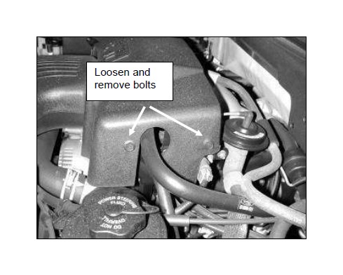
PARTS LIST
Read and understand these instructions BEFORE attempting to install this product. Failure to follow installation instructions and not using the provided hardware may damage the intake tube, throttle body and engine.
1. Preparing Vehicle
a. Make sure vehicle is parked on level surface.
b. Set parking brake.
c. If engine has run in the past two hours, let it cool down.
d. Disconnect all negative battery terminals.
e. Do not discard stock components after removal of the factory system.
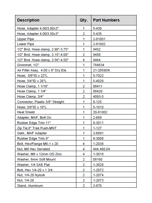
2. Removal of stock system
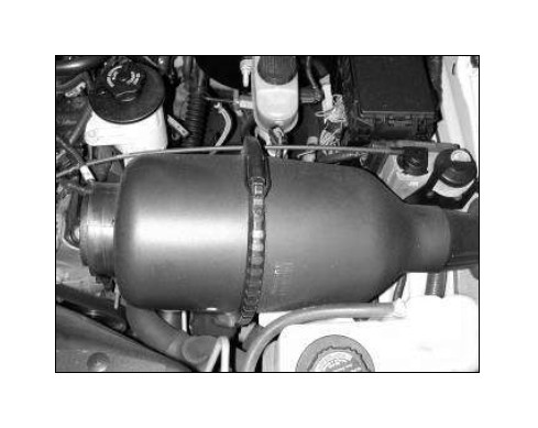
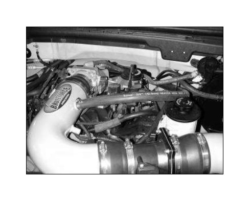
a. Stock airbox system installed.
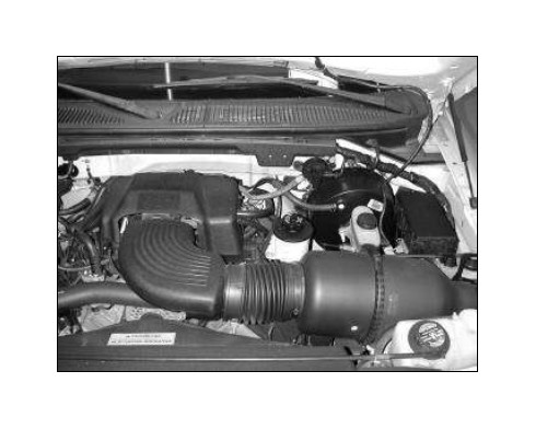
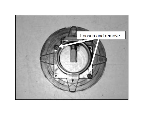
b. Loosen and remove the bolt on the left side of the throttle body cover.
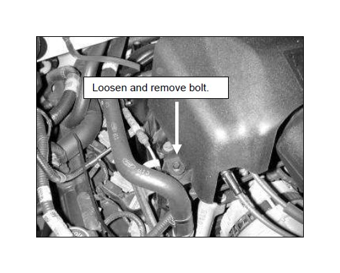
c. Loosen and remove the two remaining bolts on the driver side of the throttle body cover.
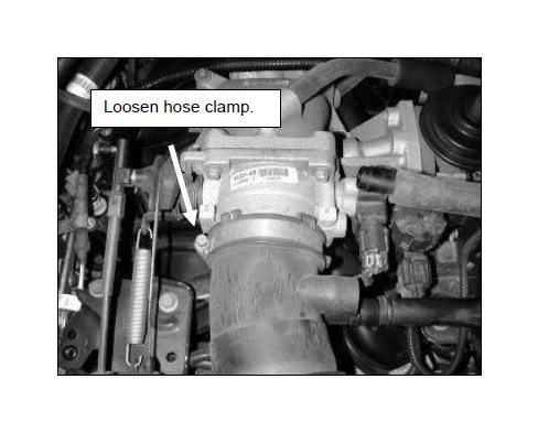
d. Once the throttle body cover is removed, loosen the hose clamp securing the inlet tube to the throttle body.
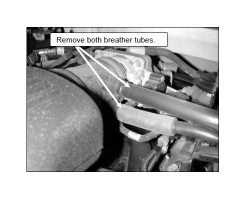
e. Remove the IAC and crankcase breather tubes from the upper air inlet tube.
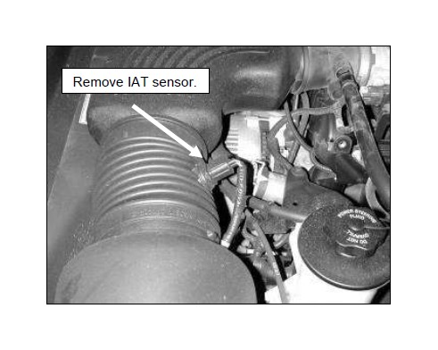
f. Remove the IAT sensor from the air inlet tube.
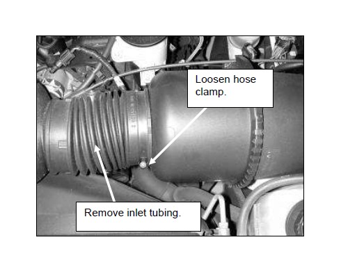
g. Loosen the hose clamp and remove the inlet tubing up to the throttle body.
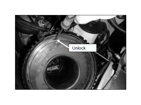
h. Unclasp the latch for the air filter and MAF sensor.
i. Unlock the MAF sensor from its housing.
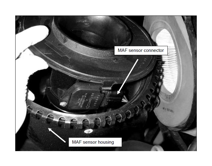
j. With the assembly open, locate the MAF sensor. Disconnect the MAF sensor and pull the connector from the housing. The MAF sensor housing will not be reused.
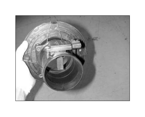
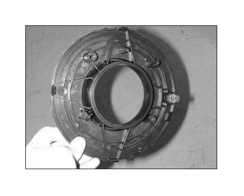
k. The stock MAF sensor assembly should look like this.
l. Remove the air filter.

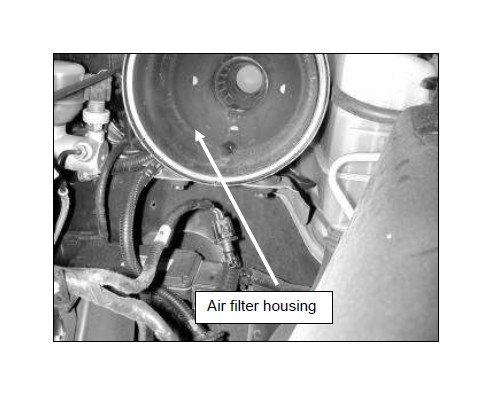
m. Remove the air filter housing.
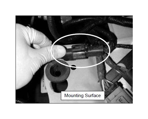
n. Remove the clip for the MAF sensor harness connector that secures it to the mounting surface. Ensure the mounting surface is level so the heat shield can be properly mounted.
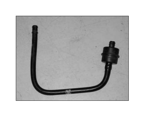
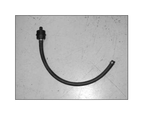
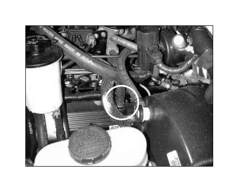
o. Remove this portion of the IAC breather tube from the vehicle. Remove the tube from the check valve, the check valve will be used with the AEM® intake system.
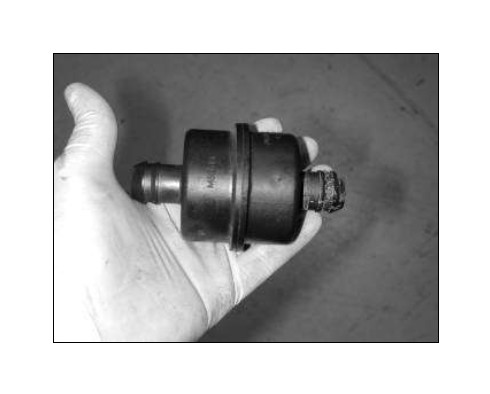
p. Check valve removed.
3. Installation of AEM® intake system.
a. When installing the intake system, do not completely tighten the hose clamps or mounting hardware until instructed to do so.
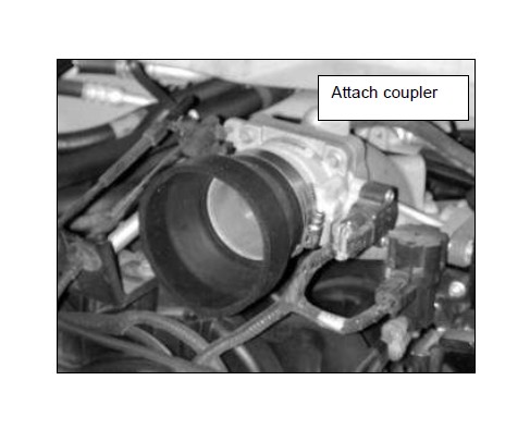
b. Attach the reducer coupler and hose clamp to the throttle body.
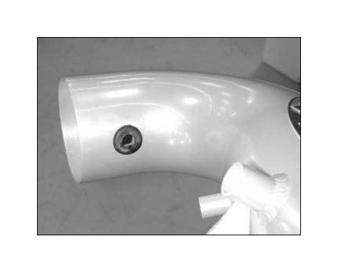
c. Insert the grommet into the upper inlet pipe.
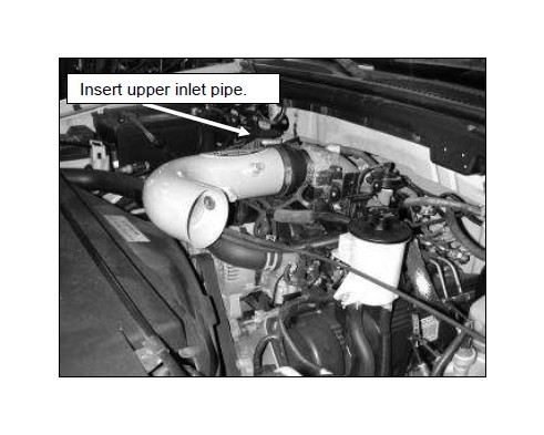
d. Insert the upper inlet pipe into the reducer coupler on the throttle body and secure with a hose clamp.
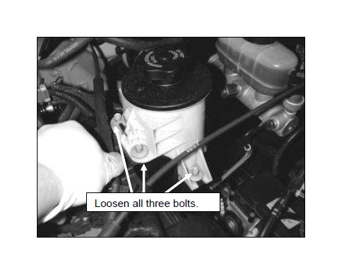
e. Loosen the three bolts securing the power steering reservoir.
f. Loosen and remove the two bolts on the stock MAF assembly.
g. This part of the stock MAF sensor assembly will not be reused.
h. The new MAF sensor assembly will contain the above hardware. 1 MAF sensor, 1 gasket, 4 M6x20 bolts, 4 nylok nuts, 4 M6 washers and the MAF sensor adapter.
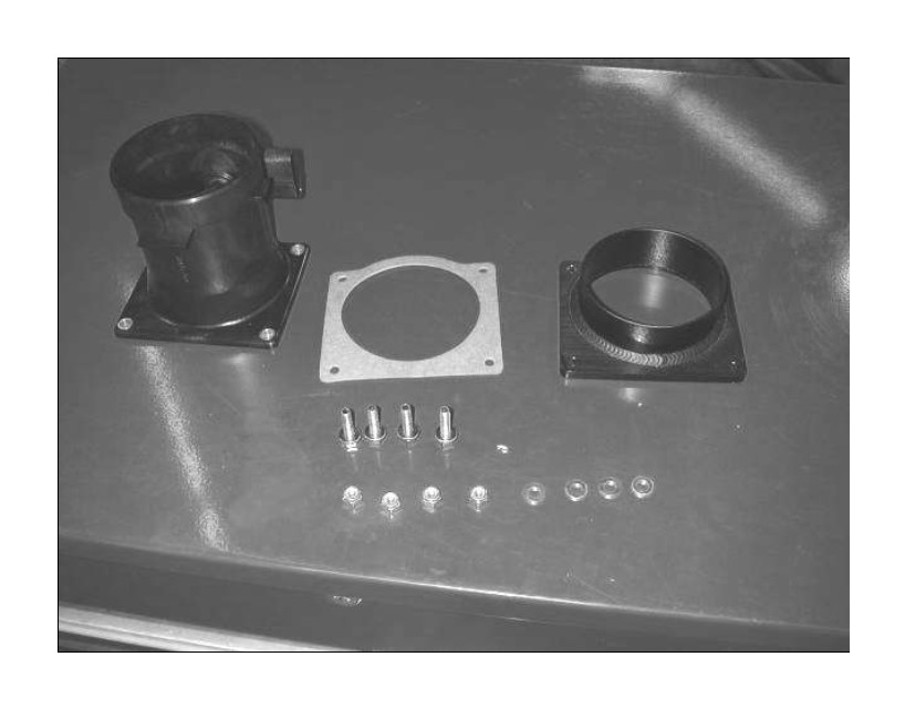
i. Assemble the MAF sensor and hardware like the assembly in the image above. The order is nylok nut, washer, MAF sensor, gasket, MAF sensor adapter, and bolt head.
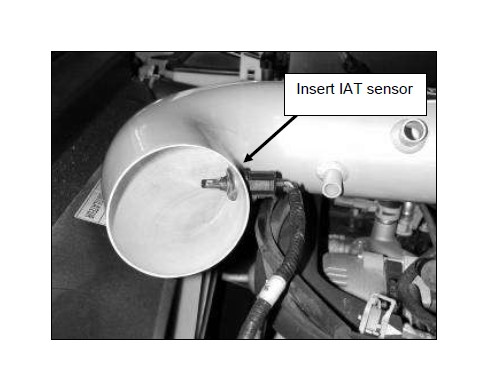
j. Insert the IAT sensor into the grommet in the upper inlet pipe.
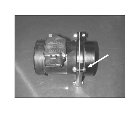
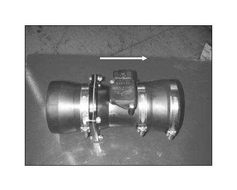
k. Attach the reducer couplers and 3 hose clamps to the MAF assembly as shown. The flow arrow is pointed to the right on the MAF sensor.
l. Attach MAF assembly to the upper inlet pipe, the flow arrow on the MAF sensor should be pointing to the upper inlet pipe.
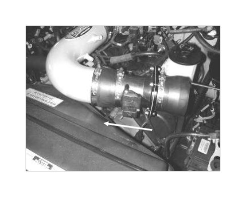
m. Insert the second inlet pipe. The bracket will be inserted underneath the tab on the power steering reservoir.
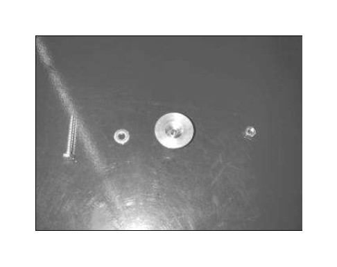
n. This is the hardware that attaches the heat shield to the mounting surface. 1 ¼-20 bolt, ¼” washer, heat shield spacer, and ¼-20 nut.
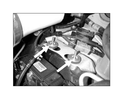
o. Insert the bolt and washer from underneath the rubber grommet. Insert the heat shield spacer and secure with the nut.
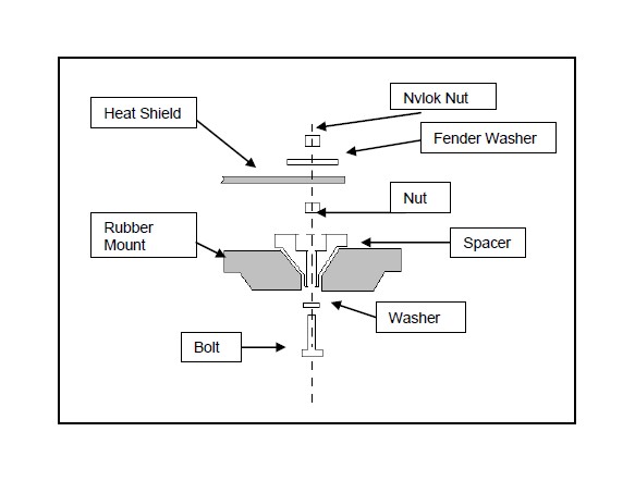
NOTE: See the diagram below on next page for the proper installation order of the heat shield and provided hardware.
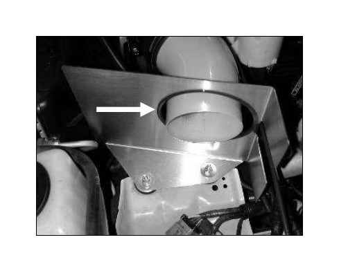
p. Attach rubber edge trim as shown. Secure the heat shield with the supplied washer and Nylock nuts. Make sure the heat shield clears the A/C line on the left and the cruise control on the right.
NOTE: Heat shield may differ from the one pictured, some require the removal of two bolts on the cruse control module and the installation of a zip-tie to secure the throttle cable to the heat shield.
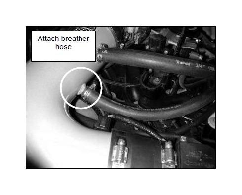
q. Attach breather hose for the IAC and secure it to the check valve.
NOTE: If your check valve is located in front, next to the throttle body you will need to trim the hose to approximately 6”.
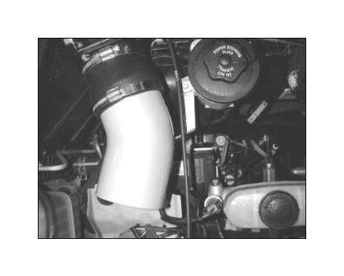
r. Secure IAC’s breather hose to the upper nipple on the inlet pipe.
s. Attach the check valve back to its original spot near the firewall.
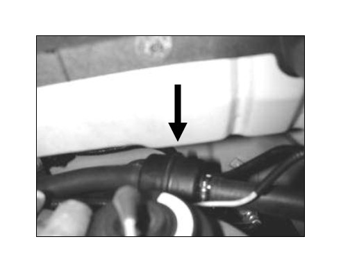
t. Attach crankcase breather tube and secure to the lower nipple on the inlet pipe.
u. Attach the other end of the crankcase breather tube to the nipple of the crankcase and secure.
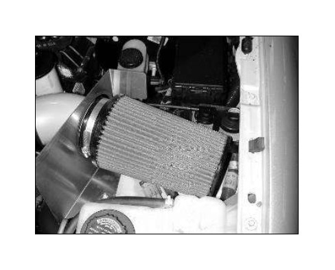
v. Attach the air filter to the inlet pipe. Check for clearance and secure the air filter.
NOTE: Some models will have the coolant reservoir behind the filter. These models will require the coolant hose be extended using the supplied barb fitting and 3/8” hose. Use the ¾” hose clamps to secure.
w. Plug the wire harness connector back into the MAF sensor.
NOTE: Make note of the MAF sensors orientation. The sensor should be facing the hood. Failure to properly position the MAF sensor may cause a rough or low idle and poor drivability.
4. Reassemble Vehicle
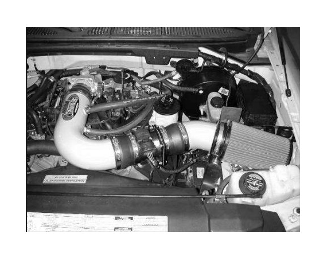
a. Position the inlet pipes for the best fitment. Be sure that the pipes or any other components do not contact any part of the vehicle. Tighten the rubber mount, all bolts, and hose clamps.
b. Check for proper hood clearance. Re-adjust pipes if necessary and re-tighten them.
c. Inspect the engine bay for any loose tools and check that all fasteners that were moved or removed are properly tightened.
d. Reconnect negative battery terminals and start engine. Let the vehicle idle for 3 minutes. Perform a final inspection before driving the vehicle.
5. CARB Sticker Placement
a. The C.A.R.B. exemption sticker, (attached), must be visible under the hood so that an emissions inspector can see it when the vehicle is required to be tested for emissions. California requires testing every two years, other states may vary.
6. Service and Maintenance
a. It is recommended that you service your AEM® Dryflow™ filter every 20,000 miles for optimum performance. Use AEM Dryflow cleaning kit part # 21-110.
b. Use aluminum polish to clean your polished AEM intake tube.
c. Use window cleaner to clean your powder coated AEM intake tube. (NOTE: DO NOT USE aluminum polish on powder coated AEM intake tubes).

