FREE 1 to 3-Day Delivery on Orders $149+ Details
How to Install Addictive Desert Designs Stealth Fighter Side Steps (09-14 SuperCrew) on your Ford F-150
Tools Required
- 3/16” Allen Wrench or Allen Key Socket
- 13mm Socket
- Ratchet
- Zip Ties
- Wire Crimpers
- Utility Knife
- Electrical Tape
PREPARATION
1. Disconnect the negative terminal on the battery. Park the vehicle on level ground and set the emergency brake.
2. We recommend reading through the installation instructions in whole before performing the work.
3. You will need the following tools:
a. 3/16” Allen Wrench or Allen Key Socket
b. 13mm Socket
c. Ratchet
d. Zip Ties
e. Wire Crimpers
f. Utility Knife
g. Electrical Tape
Note: this installation requires 2 people for best results
4. Included in Kit:
16 – Button Head Bolts – 5/16”-18 x 1”
16 – Flat Washers – 5/16”
16 – Extruded U-Nuts – 5/16”-18
1 – LED Light Harness
REMOVAL
1. If your truck did not come with OEM Side Steps, please move to the installation part of this guide.
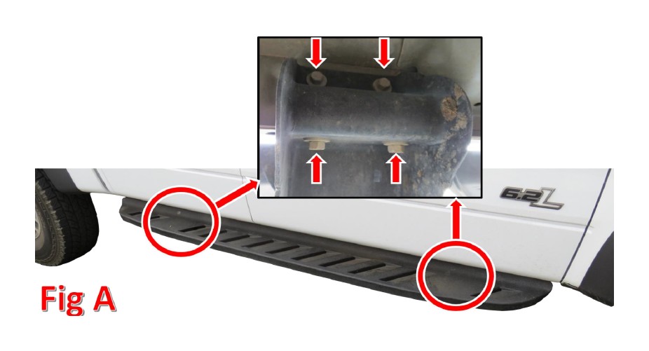
2. From the bottom of the truck, locate the eight 13mm bolts holding the OEM Side Step to your truck. There are 4 bolts per mount and two mounts per step. (Fig A)
3. Repeat Step 2 on the other side of your truck.
4. Remove the OEM Nut Clips from their locations.
5. Prepare to install your new ADD Stealth Fighter Side Steps.
INSTALLATION
1. Install the provided 5/16” U-Nuts (x8) in the same location you took the OEM U-Nuts out of. If your truck did not come with OEM Side Steps, lay your new side steps out and install the provided 5/16” U-Nuts in the holes that line up with the mounts on your steps. (Fig B)
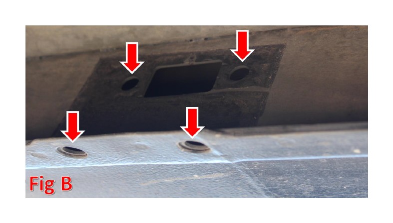
2. Hold your new ADD Side Steps in place and loosely install the provided 5/16” Bolts (x8) and Washers (x8). (Fig B)
3. Align the Side Step so that it sits straight in relation to the bottom of the truck body, then tighten the mounting bolts to 20 foot pounds.
4. Repeat Steps 1-3 on the opposite side of the truck.
5. If you have a 2009-2014 F150 or Raptor and your side steps are equipped with LED Lighting, please follow Steps 6-14. If you have a 2004-2008 F150 and your side steps are equipped with LED Lighting, please follow Steps 16-23. If your side steps are not equipped with LED lighting, please skip to Step 24.
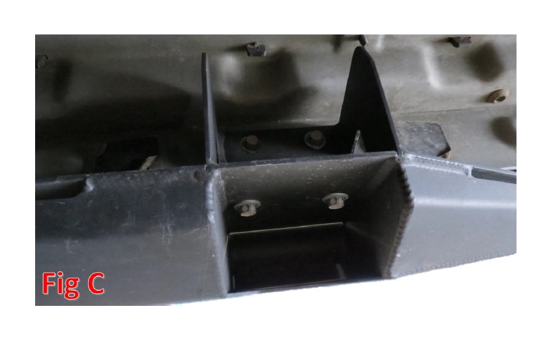
6. Lay the LED Wiring Harness out. Pass it underneath the vehicle, through the transmission cross member, so that the single end is on the driver side of the truck. (Fig C &D).
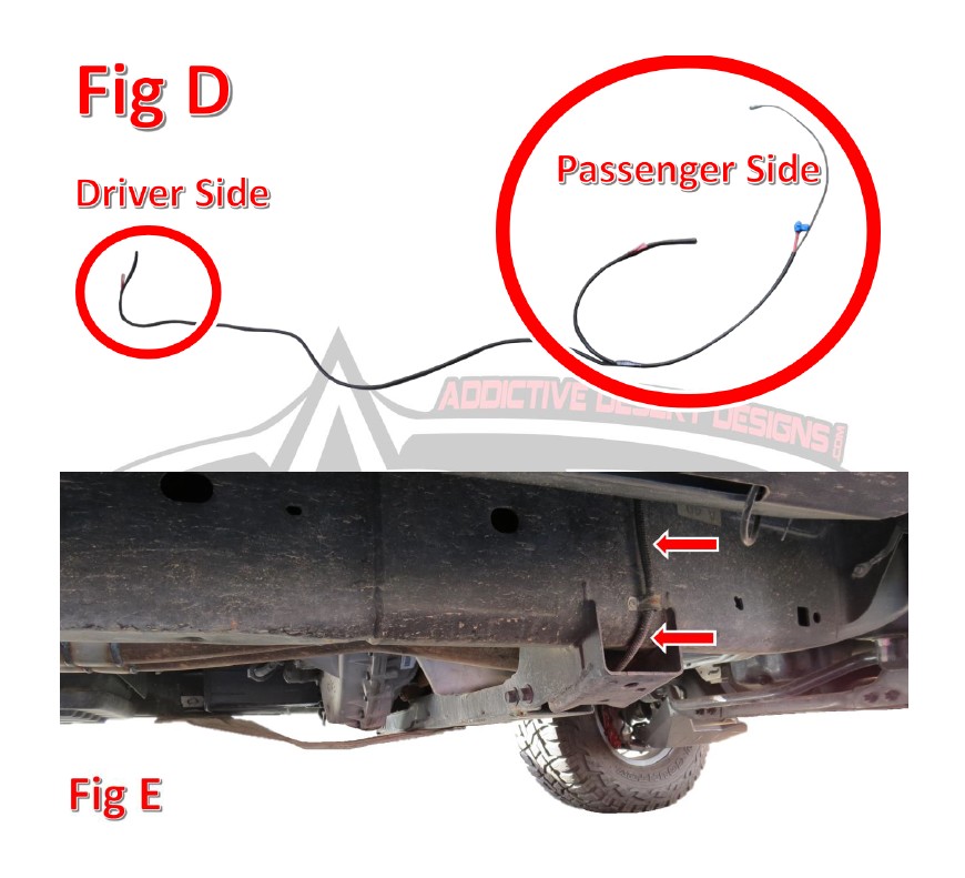
7. On the driver side of the vehicle, connect the red and black wires on the LED Harness to the red and black wires on the Side Steps. Use the butt connector already attached to the wires on the harness to make this connection. Attach the red to red and black to black. If there is any exposed wiring when you’re done making the connection, cover it with electrical tape. (Fig E) Use zip ties to secure the harness and prevent any loose hanging wires.
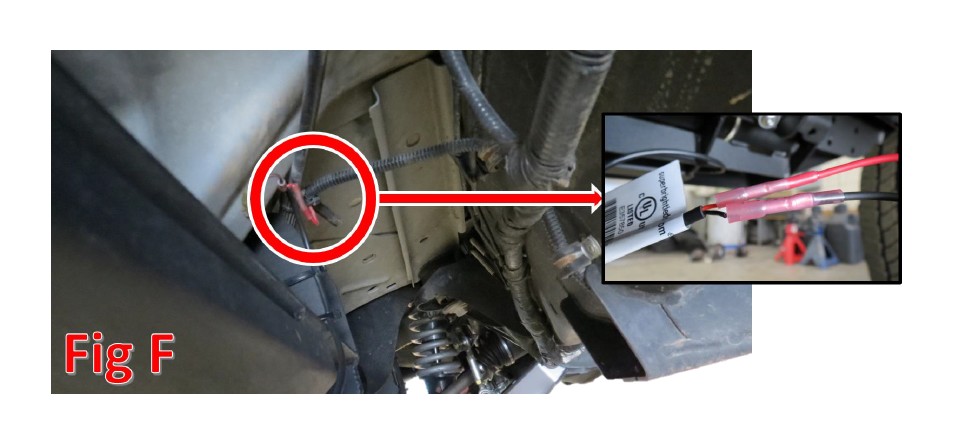
8. On the passenger side, attach the red and black wires (with butt connectors attached to them) from the LED Harness to the Red and Black wires coming from the passenger side step. Again, attach them red to red and black to black. If there is any exposed wiring when you’re done making this connection, cover it with electrical tape. Use zip ties to secure the harness and prevent any loose hanging wires.
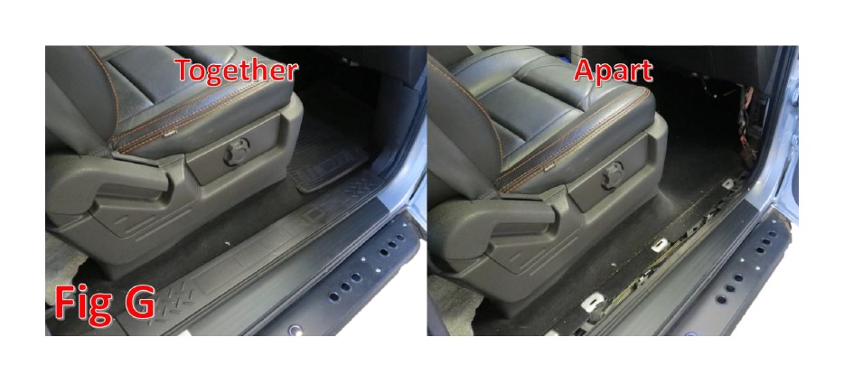
9. Open the passenger door and remove the kick panels along the door sill. There are no tools required for this step, they pull out by hand. (Fig G)
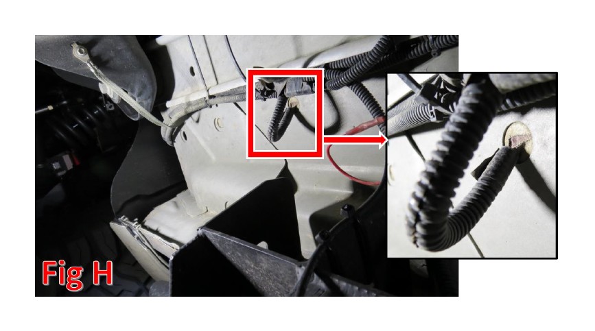
10. Take the two remaining wires (one red and one black) in the LED Harness and pass them through the hole in the floorboard referenced in Fig H. There is a piece of fabric tape covering that hole. Cut a slit in the fabric tape just big enough to pass the harness through. With the kick panels pulled, you will be able to lift the carpet to retrieve the wire from the inside of the cab.
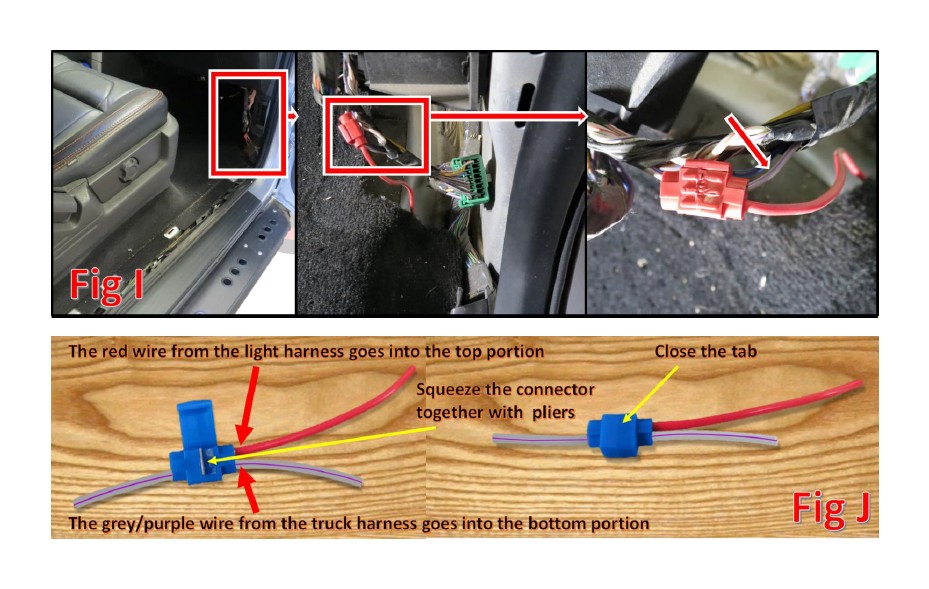
11. Under the kick panels that were removed in Installation Step 9, there is a green connector (Fig I). Find the wire that is grey with a purple stripe. Attach the remaining red wire in the LED Harness to the grey/purple wire using the attached splice connector. Fig J explains how the splice connector works, while Fig I shows where to find the green connector and the grey/purple wire coming from it.
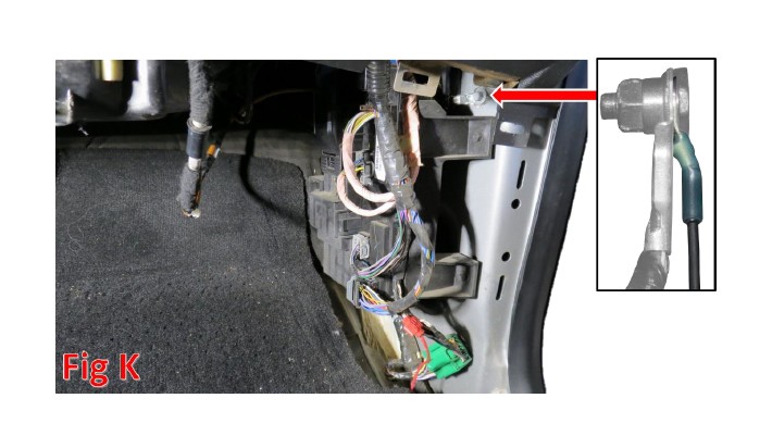
12. Find the bolt referenced in Fig K. Take this bolt out, put the connector attached to the remaining black wire in the LED Harness underneath the bolt head, and reinstall the bolt.
13. Reconnect your battery terminals. Open one of your doors and ensure that the LED lights in your side steps turn on.
14. Reinstall the panels you removed in Installation Step 9.
15. If you have a 2004-2008 Ford F150, please follow Steps 16-23 for Side Step Wiring Information.
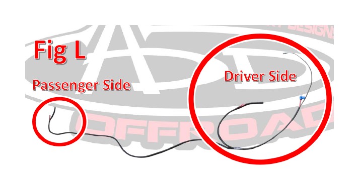
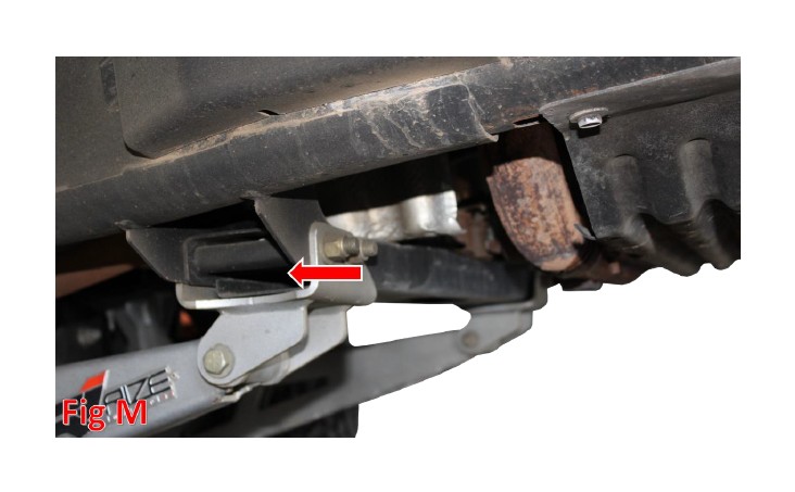
16. Lay the LED Wiring Harness out. Pass it underneath the vehicle, through the transmission cross member, so that the single end is on the passenger side of the truck. (Fig L &M).
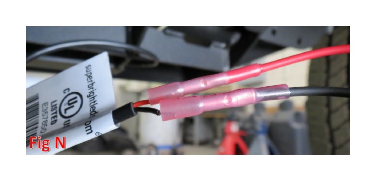
17. On the passenger side of the vehicle, attach the red and black wires (with butt connectors attached to them) on the LED Light Harness to the red and black wires coming from your side step. Connect the red to the red and the black to the black. (Fig N) Repeat this step on the driver side. If there is any exposed wiring when you’re done making this connection, cover it with electrical tape. Use zip ties to secure the harness and prevent any loose hanging wires.
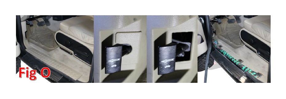
18. Open your driver side door and remove the two kick panels. First, pull the door sill panel up and out of the way. Then, pull your rubber door seal up and out of the way. In order to remove the kick panel with the hood latch release going through it, you have to remove the part around the hood latch release first. Do this by pulling the top part of this piece outwards, towards the rear of the truck. (Fig O)
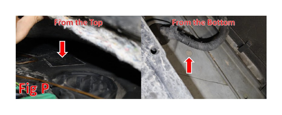
19. There is an access hole on the floorboard of the driver side, underneath the carpet. Lift the carpet to find this hole. It is covered in tape. Cut a slit through the piece of tape and pass the remaining wires (one red with a splice connector and one black with an eyelet) through the hole and into the cab. (Fig P)
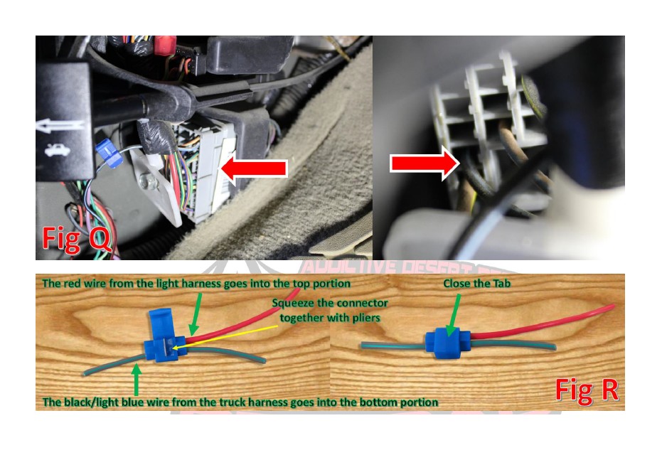
20. There is a grey connector underneath the kick panels you removed in Installation Step 18. On this connector, there is a black wire with a light blue stripe. This black/blue wire is in the column closest to the outside of the vehicle. Fig Q shows the connector and the wire. Using the attached splice connector, attach the remaining red wire on the LED Harness to the black/blue wire. Fig R explains how the splice connector works.
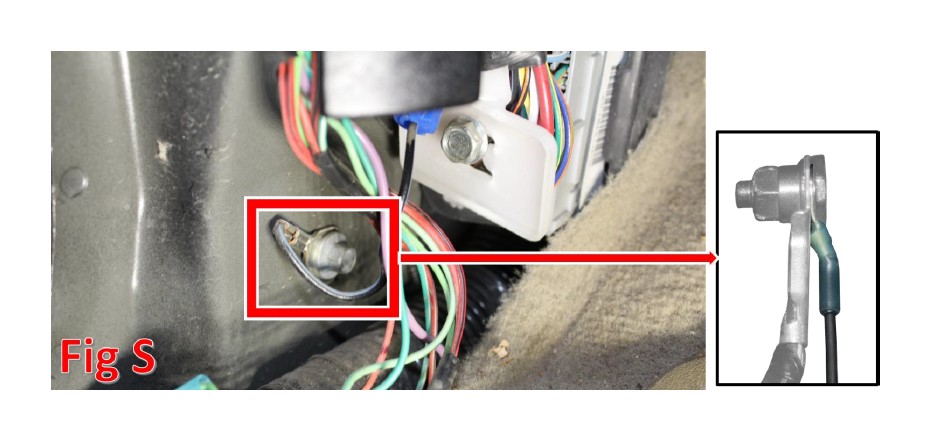
21. Directly in front of the grey connector, there is a ground bolt. Loosen this bolt, slide the eyelet attached to the remaining black wire underneath the bolt head, then retighten the bolt. (Fig S)
22. Reconnect your battery terminals. Open one of your doors and ensure that the LED lights in your side steps turn on.
23. Reinstall the panels you removed in Installation Step 18.
24. Stand back and enjoy your new ADD Stealth Fighter Side Steps.
25. Check and re-tighten if needed, all mounting bolts after 100 miles and periodically thereafter.